4 5
KOBE
INDUSTRIAL
AIR TOOLS
KOBE
INDUSTRIAL
TOOLS
ASSEMBLY & INSTALLATION
Fig. 3
Fig. 4
KOBE
INDUSTRIAL
TOOLS
OPERATION
KOBE
INDUSTRIAL
TOOLS
ASSEMBLY & INSTALLATION
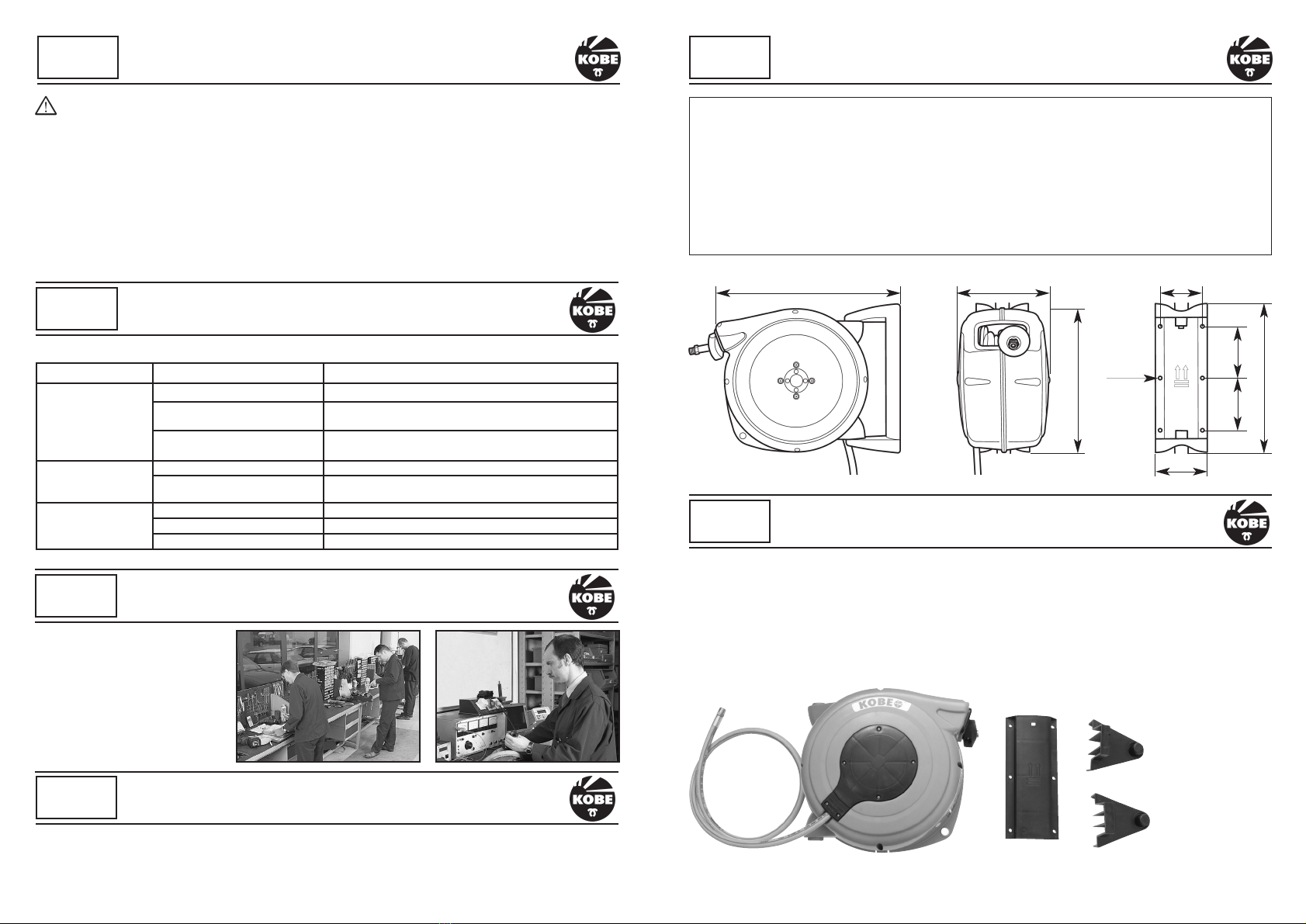
The Hose Reel can be mounted to either a wall or ceiling. Ensure the wall, ceiling or other structure, to
which the Hose Reel is to be attached to, is of sound construction and the securing points and fixings will
hold the the working strain exerted onto the Hose Reel when in use. Remember that the Hose Reel will be
heavier when it is used to transfer water.
1. If wall mounting,
position the Hose
Reel so that the hose is
pulled out no more than
15°in an upward or
downward direction
(See fig. 1). Exceeding
this can create undue
drag in operation and
potentially cause
premature wear to the
mouth opening of the
Hose Reel.
2. Place the bracket body
against the wall/ceiling and mark and drill appropriate holes.
3. Position the lower bracket arm onto the bottom of the bracket body
(See fig. 2).
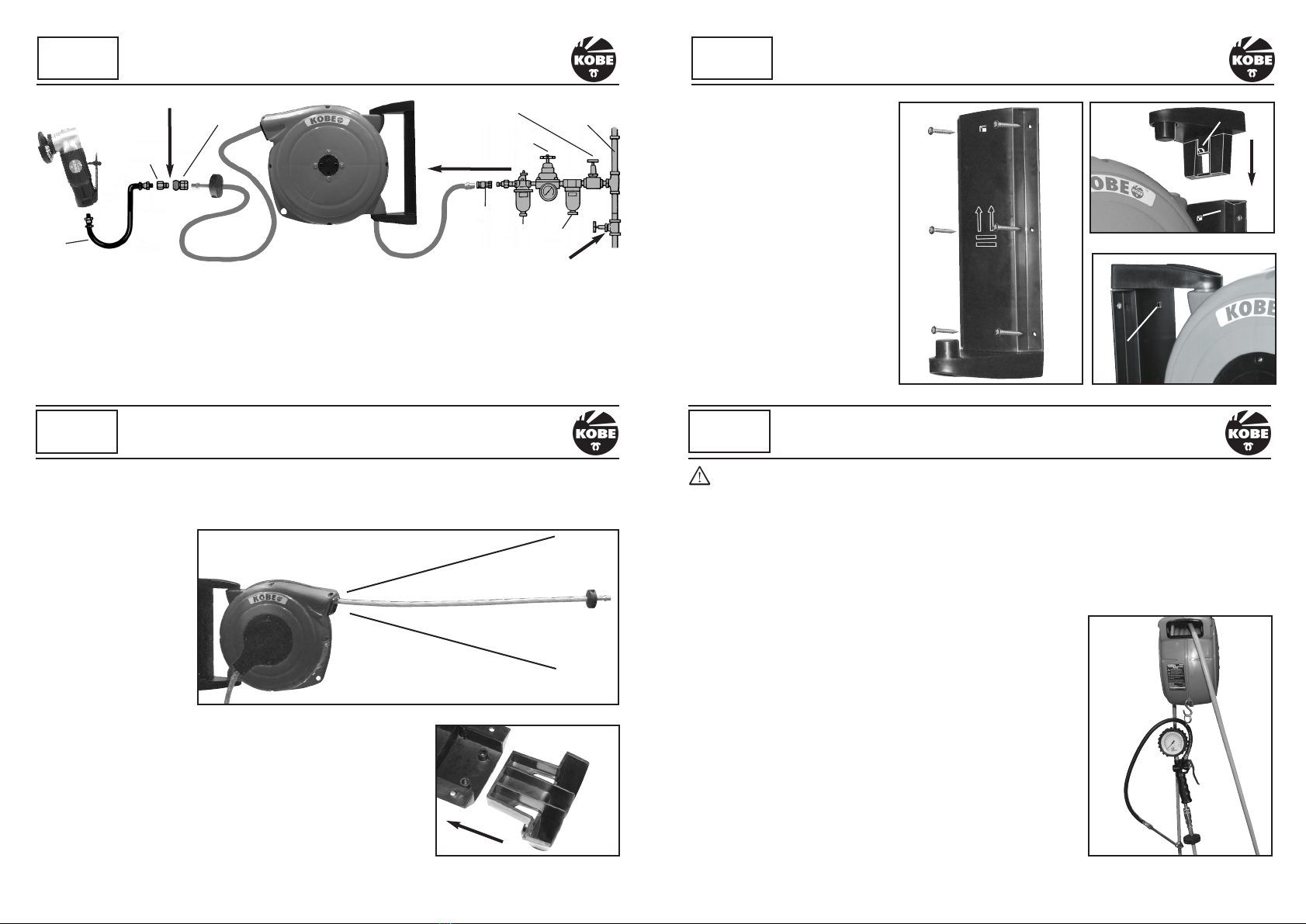
4. Screw into position making sure that the arrows on the bracket
body are facing upwards if the Hose Reel is being mounted on a
wall (See fig. 3). It is important that all six screw holes are used.
5. Mount the Hose Reel onto the lower bracket arm.
6. Slide the upper bracket arm onto the Hose Reel making sure that
clip “A” fully engages into hole “B” (See fig. 4).
Fig. 1
Fig. 2
Fig. 5
Always keep a firm hold of the hose as it is retracting back into the reel. Never allow the hose to
fly back uncontrolled as this could cause damage to property, yourself or other people.
In order to familiarise yourself with the function of the Hose Reel, stand as close as possible to it and
follow the steps below:
EXTENDING OUT AND LOCKING
1. Pull the hose slowly out and you will hear a clicking noise. This is the locking pawl running over the
locking teeth.
2. As soon as you hear the clicking noise, stop pulling and allow the hose to retract a little and it will lock
in position.
3. If it will not lock, allow the hose to retract back further, then pull it out again slowly until you hear the
first one or two clicks. Stop pulling and allow the hose to retract a
small amount and it will lock in position.
4. Now pull it out some more until you hear the next set of clicks and
repeat the locking process. The hose will lock about every 1 metre
(3 feet). The hose can be pulled all the way out until it stops.
Once you are familiar with the system, you will not need to listen for the
locking clicks as you will automatically know when and where it locks.
RETRACTING
1. Pull the hose out a little until you hear the clicking stop. The ratchet
pawl will make a “clunk” noise.
2. As soon as you hear the “clunk” sound allow the hose to retract
back whilst holding it firmly.
3. If you want to stop the hose rewinding and lock into position again,
pull some hose out until you here clicking. Allow it to retract a little
so that the hose locks into position.
The hole at the bottom of the Hose Reel can be used to hang air tools
or water spray guns (See fig. 6). Air tools which can not be held like this
should be removed. The “S” hook is not supplied with the Hose Reel.
KOBE
INDUSTRIAL
TOOLS
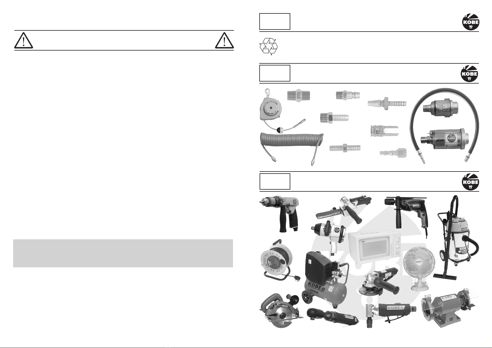
SUGGESTED AIR SUPPLY
ADAPTOR
OILER
STOP VALVE PIPES AND
FITTINGS
REGULATOR
COUPLING
OIL DAILY HERE
COUPLING
WHIP
HOSE
FILTER
DRAIN DAILY
AIR SUPPLY
Always ensure that if a hose is used between the air supply and the Hose Reel, the pressure rating of
the hose is equal to or greater than the pressure rating of the Hose Reel.
Always use thread sealants where applicable and permitted.
Never over-tighten or under-tighten fittings.
Requirements for Quick Acting Couplings connected to Air Tools:
A whip hose of minimum length 500mm between the tool and the coupling is required in order to comply
with Health and Safety Executive Guide HS(G) 39, BS4575:2, ISO 4414 and ISO 6150.
7. Connect the inlet of the Hose
Reel with the air/water supply.
Make sure the outlet has a
connection on it before switching
on slowly the air/water supply
to check for leaks.
REMOVAL
The hose must be fully retracted
before the Hose Reel is removed from
the bracket body (See below for how
to retract the Hose Reel).
Place a screwdriver into hole “B” and
push in clip “A”. At the same time
pull the upper bracket arm out a few
millimeters keeping the Hose Reel
pivoting. Whilst holding onto the Hose
Reel between your arm and body, pull
the upper bracket arm fully out (See
fig. 5).
Fig. 6
15°
15°
A
B
B
Continued
Continued on page 5