Kobold ZOK-ZxP User manual

Operating Manual
for
Flow-Counter/-Dosing Unit/-Controller
Model:
ZOK-ZxP ZOK-ExK/ZxK

ZOK-E/-Z
Page 2 ZOK K03/1115
1. Table of Contents
1. Table of Contents ......................................................................................... 2
2. Note.............................................................................................................. 3
3. Instrument Inspection ................................................................................... 3
4. Regulation Use ............................................................................................. 4
5. Environment ................................................................................................. 4
6. Instrument / Functions overview ................................................................... 5
7. Electrical connections................................................................................... 6
7.1Cable entry for housing option -K........................................................ 6
7.2Overview of Terminals ZOK-E/Z with universal housing ‘K’ ................ 7
7.3Overview of Connections ZOK-Z with panel mount housing ‘P’ .......... 7
7.4Power Supply ...................................................................................... 8
7.5Sensor Inputs .................................................................................... 10
7.6Control Inputs.................................................................................... 15
7.7Analogue Output (only ZOK-E3K/-Z3K/-Z3P).................................... 17
7.8Switching output (only ZOK-Z2K/-Z2P/-Z3P/-Z3K)............................ 20
7.9Pulse Output and Status Output........................................................ 21
8. Operating and Menu Structure ................................................................... 22
8.1Overall............................................................................................... 22
8.2Measuring Mode................................................................................ 23
8.3Menu Mode ....................................................................................... 27
9. General Functions ...................................................................................... 28
MIN- MAX. Memory (not for ZOK-Z2P/-Z2K).............................................. 28
10.Instrument Parameters ............................................................................... 28
10.1End of instrument parameterization................................................... 28
10.2Overview of menu functions/ instrument parameters ........................ 29
10.3Signal input ....................................................................................... 32
10.4Rate Measurement............................................................................ 37
10.5Counter ............................................................................................. 38
10.6Pulse output (only Option ZOK–E3/-Z3)............................................ 38
10.7Switching outputs (only for options ZOK-Z2/-Z3) .............................. 40
10.8Dosing function (only ZOK-Z2).......................................................... 42
10.9Analogue output (only option ZOK-E3/-Z3) ....................................... 43
10.10Service .............................................................................................. 45
11.Technical Details ........................................................................................ 46
12.Ordering Details.......................................................................................... 49
13.Dimensions................................................................................................. 50
14.Declaration of Conformance ....................................................................... 51
Manufactured and sold by:
Kobold Messring GmbH
Nordring 22-24
D-65719 Hofheim
Tel.: +49(0)6192-2990
Fax: +49(0)6192-23398
E-Mail: [email protected]
Internet: www.kobold.com

ZOK-E/-Z
ZOK K03/1115 Page 3
2. Note
Please read these operating instructions before unpacking and putting the unit into
operation. Follow the instructions precisely as described herein.
The devices are only to be used, maintained and serviced by persons familiar with
these operating instructions and in accordance with local regulations applying to
Health & Safety and prevention of accidents.
When used in machines, the measuring unit should be used only when the machines
fulfil the EC-machine guidelines.
3. Instrument Inspection
Instruments are inspected before shipping and sent out in perfect condition.
Should damage to a device be visible, we recommend a thorough inspection of the
delivery packaging. In case of damage, please inform your parcel service / delivery
agent immediately, since they are responsible for damages during transit.
Scope of delivery:
The standard delivery includes:
Flow counter/-dosing unit/-controller in plastic- universal housing with wall or pipe
mounting set Model: ZOK-Z with universal housing ‘K’
OR
Flow counter/-dosing unit/-controller in panel mounting housing 96x96mm with 2
mounting clips Model: ZOK-Z with panel mount housing ‘P’
OR
Oval gear flow meter DON- with electronics option -Z in compact version
Model: ZOK-Z with universal housing ‘M’
Operating Manual
Battery 3.6 V Lithium size AA for data saving function (not for ZOK-Z with ‘P’)

ZOK-E/-Z
Page 4 ZOK K03/1115
4. Regulation Use
The electronic units ZOK-xx are specifically designed for the calculation, display and
transfer of calculations and flow rates of flow meters with pulse or frequency outputs.
The instruments display flow rate, day counter (resettable) and total counter in the
operator-selected units. A clear multilingual menu guides you through the
programming of the device that largely eliminates the requirement of constant usage of
operating manual. All user-specific program settings are retained even when changing
the battery.
A trouble-free operation of the device is only guaranteed if all instructions in this
manual are complied. We do not accept any liability for damage caused by failure to
follow these instructions.
5. Environment
The electronics options ZOK-ZxK are weather resistant and adequately reflect IP66/67
(NEMA 4X). The electronics are housed in a UV-resistant, glass-filled nylon housing
with stainless steel screws and FPM seals. The options ZOK-ZxP are in a panel mount
housing 96x96 mm with protection class IP44. The instruments are suitable for harsh
indoor or outdoor environments and comply with EU Directive 2004/108/EC
(Electromagnetic Compatibility).

ZOK-E/-Z
ZOK K03/1115 Page 5
6. Instrument / Functions overview
Function Z1P Z1K Z2P Z2K Z3P Z3K E1K E3K
Dual Counter x x
xxxx
Dosing function xx
Controller function
xxx
Certification
ATEX Certification
xx
Power supply
DC-Supply
x x xxx x xx
AC-Supply
xxx
Battery
operation x
x x x
4-20 mA Loop x x
Sensor supply (only with external power supply)
Sensor supply 8 V/
23 V 8 V 8 V/
23 V 8 V 8 V/
23 V 8 V 8 V 8 V
Electrical outputs (only with external supply)
Relay outputs x x x
Transistor outputs xx
Analogue
outputs
3 L 2 L/
3 L 2 L/
3 L
Pulse outputs
xx
LCD display
Selectable units x x x xxxxx
Decimal point xxxxxxxx
Accumulative total xx x xxx x x
Resettable total x x x x x x x x
Linearisation x x x x x x
Rate display x x x x x x x x
Backlighting x x x x x x x x

ZOK-E/-Z
Page 6 ZOK K03/1115
7. Electrical connections
7.1 Cable entry for housing option -K
Up to 3 cable entries (M20x1.5 or ½ "NPT) are available for electric connection in case
of electronics with plastic housing. To use these cable inlets, the existing factory
protection caps must be broken with a tool (e.g. screwdriver) and a suitable cable
gland should be screwed in. The cable glands are not included in the delivery.
Eruption of cable inlets
In case of electronic option ZOK-Z with housing ‘P’, the electrical connection is at the
rear side above the pluggable screw terminals.

ZOK-E/-Z
ZOK K03/1115 Page 7
7.2 Overview of Terminals ZOK-E/Z with universal housing ‘K’
7.3 Overview of Connections ZOK-Z with panel mount housing ‘P’
Battery 3,6V
2200mAh
Size AA
+
-

ZOK-E/-Z
Page 8 ZOK K03/1115
7.4 Power Supply
Depending on functionality and features, the electronics offer different possibilities for
power supply:
Options ZOK-Z2: External DC-Supply
Options ZOK-Z1: Battery and ext. DC-Supply
Options ZOK-Z3: Battery and ext. DC-Supply and 4-20 mA
Loop current
7.4.1 Storing the counter readings
The storage of meter readings is carried out after each measurement cycle in the
internal FRAM. If the power is interrupted and re-applied, than the meter reading revert
to the last saved values.
7.4.2 External DC-Supply
When electronic units are supplied with external DC voltage, all functions are
available. If no analogue output is used, all instrument functions are ensured on 5 VDC.
When using the analogue output in 3-wire circuit, the supply voltage must be minimum
10 VDC (+ load).
7.4.3 Supply via 4-20 mA Current Loop (only ZOK-Z3K)
The electronic option ZOK-Z3K can alternatively be operated via 4-20 mA current loop
in 2-wire operation. Here we have the following technical limitations:
All other electrical outputs (switching outputs, pulse output and status output) are
disabled
The backlight of the display is switched off and cannot be turned on.
Sensors that do not require an additional power supply can be connected (e.g.
reed switch). Hall sensors require the additional power supply and can therefore
not be used in 2-wire loop operation. In this case, the 3-wire connection must be
used with an external power supply.
To use the 2-wire loop operation, the parameter ‘Wiring type’ in configuration
menu for analogue output must be changed to ‘2-wire’, otherwise the current
output will not be scaled correctly.
For electronics option Z2, no battery can be used due to the relay
board.
If the device is taken out of operation and not used for longer periods,
the battery must be removed. Otherwise, the device is always supplied by
the battery and remains active. As a result, the battery can get discharged.

ZOK-E/-Z
ZOK K03/1115 Page 9
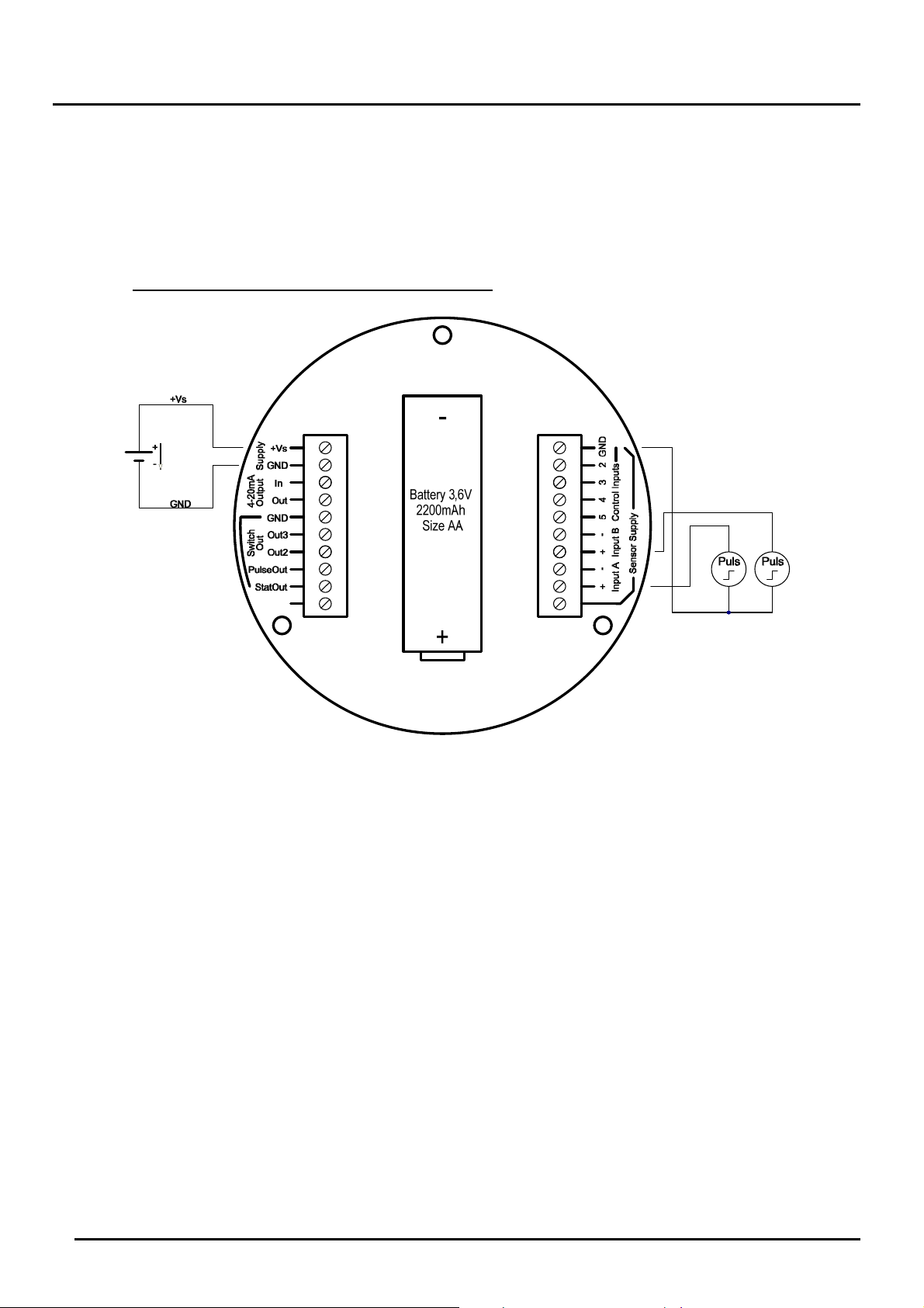
7.4.4 Battery operation (only ZOK-Z1K/Z3K)
The options ZOK-Z1/-Z3/-E1/-E3 can also be powered by a battery. In battery mode,
the device function scope is relatively limited:
All electrical outputs (switching outputs, analogue output, pulse output, status
output) are disabled during battery operation.
The backlight of the display is switched off and cannot be turned on.
The sensor may only be used with passive reed switches, as they require no
additional power supply. Usage of induction coils reduces the battery life. Other
sensors, which require a sensor power for operation, are also not suitable for
battery operation.
In battery mode, a SLEEP-Mode will be activated after about 30 seconds in case
no key is pressed. When SLEEP-Mode is active, ‘SLEEP’ will be continuously
displayed on the display. In this mode, the measured values are not displayed or
updated periodically, however all input pulses can be detected and counted at
any time. If one of the 4 buttons is pressed during the SLEEP-Mode, the normal
measurement mode is temporarily activated and all measurements will be
displayed. After about 30 sec, the SLEEP-Mode is activated again if no button is
pressed. The duration after which the electronics goes in SLEEP-Mode and
SLEEP is displayed on the display can be adjusted, activated and deactivated
with Menu point ‘Sleep Timeout’. If ‘Sleep Timeout’ is set to ‘0’, SLEEP-Mode is
deactivated and the electronics will always work in Measuring Mode. The ‘Sleep
Timeout’ can be adjusted from 0 to 1800 secs.
The charging state of the battery is monitored at all times in measurement mode
and in SLEEP-Mode. In measuring mode, an insufficient battery signal will be
showed by the blinking of “bat” symbol. In SLEEP-Mode, it will be signalled
through a display of “CHANGE BAT”. In this case, the battery should be replaced
by a new one.
The supplied battery type 3.6 V AA Lithium (2200 mAh) should be inserted in the
battery holder on the back side of the electronic (correct polarity is important!).
The following type of battery is required to replace the supplied battery:
3.6 V Lithium, Size AA, minimum capacity 2200 mAh, IEC-Type CR14505
e.g: EVE Type ER14505, SAFT LS14500, TADIRAN SL360S/SL760
Battery life duration: The achievable battery life is dependent on various factors:
- On the frequency of activation of measurement / menu mode (in the measurement /
menu mode, power consumption is higher)
- On the total number of detected input pulses and the input frequency(higher
frequencies reduce the battery life)
- On the environmental conditions - low temperatures reduce the usable battery
capacity.
The average life span is approximately 12 months. Within this time, the service
intervals for checking the battery status should be determined.

ZOK-E/-Z
Page 10 ZOK K03/1115
7.5 Sensor Inputs
7.5.1 Active pulse signal
Power Supply: External DC-Supply
Signal input setting: „AKTIVES SIGNAL“
Wiring for ZOK-Z with universal housing ‘K’:

ZOK-E/-Z
ZOK K03/1115 Page 11
Wiring for ZOK-Z with panel mount housing ‘P’:
7.5.2 Hall Sensor, NPN- and PNP-Sensors
Power supply: only external DC-supply
Signal input setting: „HALL“
Signal input setting: „NPN“
Signal input setting: „PNP“
Wiring for ZOK-Z with housing ‘K’:

ZOK-E/-Z
Page 12 ZOK K03/1115
Wiring for ZOK-Z with panel mount housing ‚P‘:
7.5.3 Reed switch (-R0 Sensor option)
Power supply : External DC-supply, Battery operation or
4-20 mA loop current
Signal input setting: „REED “
Wiring for ZOK-Z with universal housing ‘K’:

ZOK-E/-Z
ZOK K03/1115 Page 13
Wiring for ZOK-Z with panel mount housing ‘P’:
7.5.4 Inductor
Power supply: External DC-supply and battery operation
(Battery operation reduces battery life)
Signal input setting: „Inductor“
Wiring for ZOK-Z with universal housing ‘K’:

ZOK-E/-Z
Page 14 ZOK K03/1115
Wiring for ZOK-Z with panel mount housing ‘P’:
7.5.5 Namur-Sensor
Power supply: only external DC-supply
Signal input setting: „NAMUR“
Wiring for ZOK-Z with universal housing ‘K’:

ZOK-E/-Z
ZOK K03/1115 Page 15
Wiring for ZOK-Z with panel mount housing ‘P’:
7.6 Control Inputs
There are 3 control inputs for external controlling of instrument functions. The
activation of each function can be done through:
a.) an active control input or
b.) Carried out by a passive N/O contact.
In both cases, the function will be activated on switching from HIGH to LOW level
(falling edge).
When using an active control signal, the signal amplitude of the HIGH level must be
from 5 to 24Vdc. When using simple normally open contact, the input potential is
internally pulled of HIGH, if the contact is open. If the contact is closed, the input
potential is pulled to GND and the control function is activated.
CTRL4 control input is not used.
Function of control inputs:
Control input ZOK-E1/-Z1
ZOK-E3/-Z3 ZOK-Z2
CTRL1 Reset MIN / MAX memory Dosing Start / Stop
CTRL2 Reset partial input A Dosing value reset
CTRL3 Reset partial input B -
CTRL4 - -

ZOK-E/-Z
Page 16 ZOK K03/1115
Wiring for ZOK-Z with universal housing ‘K’:
Wiring for ZOK-Z with panel mount housing ‘P’:
+
-
Batterie 3,6V
2200mAh
Größe AA
Battery 3,6V
2200mAh
Size AA

ZOK-E/-Z
ZOK K03/1115 Page 17
7.7 Analogue Output (only ZOK-E3K/-Z3K/-Z3P)
7.7.1 2-Wire Configuration 4-20 mA
The options ZOK-Z3/-E3 can be operated as a source in a 2-wire 4-20 mA current
loop. However, only passive Reed switch (option -R0) should be used as a sensor. In
2-wire loop operation, no other active outputs are available. If the electronics is
connected in 2-wire configuration, the display will show „LOOP“ at the top. The wiring
type must be set to "2-WIRE" in the Analogue Output menu.
7.7.2 3-Wire Configuration as active output, current source
In the 3-Wire Configuration, the load is connected between current output (-) and
GND and all types of sensors can be connected and all other outputs can be used. If
the electronics is connected in 3-wires, the display will show „EXT“ at top left
(external power supply). The wiring type must be set to "3-WIRE" in the Analogue
Output menu. All sensor types can be connected at the signal input.

ZOK-E/-Z
Page 18 ZOK K03/1115
Wiring for ZOK-E3K/-Z3K:

ZOK-E/-Z
ZOK K03/1115 Page 19
Wiring for ZOK-Z2P/-Z3P:
7.7.3 3-Wire Configuration as passive output, current sink
(only ZOK-E3K/-Z3K)
In the wiring 3-wire passive current sink, the load (load) is connected between
current output (+) and voltage source (+Vs). In the 3-conductor wiring, all types of
sensors can be connected and all other outputs can be used. If the electronic is
connected in 3-conductor wiring, the display will show „EXT“ at top left (external
power supply). The wiring type must be set to "3-WIRE" in the Analogue Output
menu. All sensor types can be connected at the signal input.

ZOK-E/-Z
Page 20 ZOK K03/1115
7.8 Switching output (only ZOK-Z2K/-Z2P/-Z3P/-Z3K)
7.8.1 Transistor Output
The transistor outputs can be configured by software as PNP, NPN or push-pull
output. In case of push-pull configuration, output will be switched between active-
HIGH or LOW potential. The load can either be connected to GND or + Vs. In push-
pull mode, no additional pull-up or pull-down resistor is required.
7.8.2 Relay outputs (for ZOK-Z2P/-Z2K/-Z3P)
The electronics options ZOK-Z2/-Z3 devices are equipped with potential-free relay
outputs as standard. Electronic option ZOK-Z2 is equipped with an additional relay
board. These relay outputs can be simultaneously used in parallel with the existing
transistor outputs. The outputs of the relay 1 are controlled by the switching output
SW1 and of relay 2 by SW2.
Wiring for ZOK-Z2K:
out
p
ut
Other manuals for ZOK-ZxP
1
This manual suits for next models
2
Table of contents
Other Kobold Cash Counter manuals