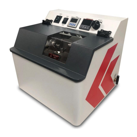
Koehler K93500 Guide

Pin On Disc Friction & Wear Test Rig
Page 1
K93500 / K93590
Pin On Disc Machine
Operation and Instruction Manual
REV A
Koehler Instrument Company, Inc.
1595 Sycamore Avenue • Bohemia, New York 11716-1796 • USA
Toll Free: 1-800-878-9070 (US only) • Tel: +1 631 589 3800 • Fax: +1 631 589 3815
http://www.koehlerinstrument.com • e-mail: [email protected]
Petroleum Testing & Analysis Instrumentation • Custom Design & Manufacturing

Pin On Disc Friction & Wear Test Rig
Page 2

Pin On Disc Friction & Wear Test Rig
Page 3
CONTENTS
1. PART I GENERAL INFORMATION
2. PART II DESCRIPTION
3. PART III INSTALLATION
4. PART IV OPERATION
5. PART V MAINTENANCE
6. PART VI CALIBRATION
7. PART VII CIRCUIT DIAGRAM
8. PART VIII BROUGHT OUT ITEMS LIST
9. PART IX TROUBLE SHOOTING
10. PART X SOFTWARE INSTALLATION GUIDE

Pin On Disc Friction & Wear Test Rig
Page 4
PART I
GENERAL INFORMATION
WARRANTY
The equipment is under warranty for a period of 12 months from the date of supply
against manufacturing defects only. The damages occur due to improper use, power
fluctuation etc., are not covered under this warranty.
When the consignment reaches to your place, please check the items as per the list
provided along with the machine. If any parts are missing or any damages found please
inform us through mail or call immediately.

Pin On Disc Friction & Wear Test Rig
Page 5
SAFETY PRECAUTIONS
The Pin on Disc Friction & Wear Test Rig is an electro-mechanical Device. Please
follow the instructions carefully.
Personnel injury may be resulted by improper operation.
The equipment may be damage by improper operation.
Only our service engineer installs and services the equipment.
Please ensure proper earthing.
Voltage between Earth and Neutral should be less than ±5 Volts.
Do not attempt at wire circuitry while power is ON.
Do not attempt to examine the components and signals when the equipment is ON.
Do not attempt to disassemble or modify internal circuitry or wiring.

Pin On Disc Friction & Wear Test Rig
Page 6
PART II
DESCRIPTION
The Pin on Disc Friction & Wear Test Rig is intended for determination of tribological
properties of different materials.
(i) Ascertain the validity of law’s of friction
(ii) Wear characteristics of the given specimen
(iii) Determination of wear constant
(iv) Understand the effect of parameters
This is a study versatile machine, which facilitates study of friction and wear
characteristics in sliding contacts under desired conditions. Sliding occurs between the
stationary pin and a rotation disc. Normal load, rotational speed and wear track diameter
can be varying to suit the test conditions. Frictional force and wear (displacement) are
monitored through electronic sensors and recorded to PC.
The major parts of the wear and friction monitor are mechanical assembly, Base plate,
Guide Base, AC Motor, AC Drive and spindle assembly, loading arrangement with 1:1
leverage ratio with a pulley, loading pan with dead weights, wear disc holder, scale to set
the track radius, LVDT for displacement, and load cell for frictional force.
Fig.,No.,01
Base Plate
Guide Base
Sensors
Wear Disc EN 31
Mtrl,58-60HRC

Pin On Disc Friction & Wear Test Rig
Page 7
Fig.,No.,02
Fig.,No.,03
Spindle
AC Motor
AC Drive
Environmental
Chamber
Lubricating
Re circulating
Chamber
Step down
transformer
230V to 110V

Pin On Disc Friction & Wear Test Rig
Page 8
Fig.,No.,04
Load up to 20 Kg can be applied on the specimen through loading lever arrangement,
which consists of loading pan and dead weights.
Dead Weights
Loading Pan
Loading Lever

Pin On Disc Friction & Wear Test Rig
Page 9
Fig.,No.,05
It also consists Power “ON” RCCB, 3 Pin Main power input harting connector, 19 Pin MS
connector, 9 Pin ‘D’ Type connectors for load cell & LVDT and 15 Pin ‘D’ Type signal
output connector, 2 Pin ‘K’ Type Thermocouple Connector, 2 Pin allied connector for
Heater
Resistance Control
Circuit Breaker (RCCB)
19 Pin M.S.Connector
5 Pin Main Power Input
Connector
9 Pin ‘D’ Type
Connector for LVDT
9 Pin ‘D’ Type Connector
for Load cell
2 Pin allied connector
for heater
2 Pin ‘K’ Type
Thermocouple
connector
15 Pin ‘D’ Type Signal
Output Connector

Pin On Disc Friction & Wear Test Rig
Page 10
Technical specifications of PIN ON DISC FRICTION & WEAR TEST RIG:
1. Normal Load Range - Up to 200N
2. Frictional Force Range - Up to 200N with a resolution of 1
N with tare facility
3. Wear Measurement Range - ± 2mm with tare facility
4. Sliding Speed - 0.26 to 12 m/s
5. Disc Speed - 50 to 2000 rpm
5. Preset Timer Range - Up to 99hrs:59min
6. Wear Disc Diameter - 165mm, Thk-8mm (EN 31 disc 58-60
HRC)
7. Wear Disc Track Radius - 10mm to 70mm
8. Specimen Pin Diameter/Diagonal - 3mm to 12mm
9. Pin Length - 25mm to 30mm
10. Data Acquisition System - Up to 8 channels with National
Instruments USB DAQ Card
11. Pin Heating System - Up to 2500C
12. Lubricating Re-circulating System
13. Specimen Holders - Ball, Square & Rectangular
14. Environmental Chamber with view port for inert gases and steam
15. Wear Disc

Pin On Disc Friction & Wear Test Rig
Page 11
PIN DISC FRICTION & WEAR TEST RIG -CONTROLLER
Test parameters such as wear, frictional force, test speed, test duration and pin
temperature can be read with the front panel of the controller box. The wear, frictional
force and temperature of the specimen are continuously displayed.
The front panel also consists of power “ON” switch.
“Zero” to set “Wear” and “Frictional Force” displays through software
“SET RPM” potentiometer to be set the speed.
To set “pre-set timer” soft buttons are provided.
To set the different test speeds a variable knob is provided which has to rotate in
clockwise direction.
The back panel of the controller consists of MS-Shell connector; “D” type connectors
for signal input and data acquisition NI CARD cable .
Fig.,No.,06
Fig.,No.,06
Friction Force RPM Variable Pin Temperature Cycle Start/Stop
(In N) Knob Controllers & Indicator) Push Buttons
(In 0C)
Wear Test Speed Preset Timer Power ON/OFF
(In µ) (in RPM) Switch

Pin On Disc Friction & Wear Test Rig
Page 12
Back Panel of Controller
Fig. No.07
Data acquisition cable one end is fitted with the NI USB 6008 A-D card, other end has to be
connected to PC, which sends signals received from Sensors to PC.
MS Connector FUSE Data Acquisition Cable Signal Input Connector

Pin On Disc Friction & Wear Test Rig
Page 13
POWER INPUT CABLE (Fig.No.08)
It is a 3-core cable with 4 pin harting connector end to supply 110V input supply to machine.
CONTROL CABLE (Fig.No.09)
It is a 19 pin MS connector cable which carries power from the controller to machine panel.
SIGNAL CABLE (Fig.No.10)
This connects machine front panel to controller back panel, it sends the signals of frictional
force and LVDT sensor to controller. It is 15 pin D type connector.

Pin On Disc Friction & Wear Test Rig
Page 14
DATA ACQUISTION SYSTEM INCLUDES.
a) Data acquisition cable fixed with controller (USB Cable)
b) DATA ACQUISITION SYSTEM
Fig.No.11
Data Acquisition and Data Processing.
Analog data is converted into digital and processed in the NI data card. It is logged to
PC through data acquisition cable. The data is received, displayed and stored on the PC
using Lab view based software of national instruments “DATA ACQUISITION
SOFTWARE”. (Refer Software Installation Instruction guide).

Pin On Disc Friction & Wear Test Rig
Page 15
PART III
INSTALLATION
Remove the top panel of controller and visually inspect for any damage.
Place controller box on a table connect it to machine through control cable, power cable
and signal input cable.
Connect thermocouple, load cell and LVDT cables to corresponding sockets provided on
the front door of the machine.
Connect 4-pin harting connector to machine . Connect the other end of the cable to
110V, 60Hz, 1 Phase supply plug to 3 pin power socket. Ensure proper neutral and
grounding (neutral to ground voltage should be less than 5v) of the 1 phase supply to the
machine keeps “MAINS” RCCB on the machine side in OFF position.
Keep the “POWER” switch of the controller box in OFF position.
Turn the “RPM” knob to zero position.
Connect one end of the Data Acquisition cable to the “DATA ACQUISITION” port on
the controller back panel and the other end to the USB port of the PC.

Pin On Disc Friction & Wear Test Rig
Page 16
PART IV
OPERATION
The operation of PIN ON DISC FRICTION & WEAR TEST RIG is made simple and user
friendly by providing controls and displays on the front panel of the control box. The
controls for operation are:
Wear (displacement)- to be preset to zero before start of operation
through the software.
Frictional force - to be preset to zero before start of operation
through the software.
Speed - Speed of the motor –can be set in the range of
50 to 2000 RPM.
Temperature - Pin Gradient Temperature Measurement & pin
Controller temperature controller.
Start –Stop - to start/ stop (push button switches are provided)
the system operation.
Connect the power input cable to 110V, 60Hz, and single-phase supply. Switch ON the
“MAINS” RCCB on the machine front panel.
Place the specimen pin between the jaws and adjust the height of the pin with respect
to the test disc using the thumbscrew provided on the specimen holder plate.

Pin On Disc Friction & Wear Test Rig
Page 17
SPECIMEN FIXING DETAILS:
Fig.No.12
Assembly of specimen holding unit
Fig.No.13 & 14
Fix the specimen holding unit to loading lever assembly
Fig. No.15
Adjustable
jaw
Clamping screws
Specimen
Lock nut
Specimen height
adjustment knob
Specimen holder
plate
Specimen holder
Fixed jaw
Specimen holding unit to fix the
loading lever assembly

Pin On Disc Friction & Wear Test Rig
Page 18
Height adjustment block is given to ensure that the loading arm is parallel to the plane
of the wear disc. Tighten the clamping screws on the adjustable jaw to hold the
specimen pin firmly.
Fig. No.16
Fig. No.17
Height Adjustment
Block
Clamping Screws
Thumb screw for
height adjustment
with lock nut

Pin On Disc Friction & Wear Test Rig
Page 19
Fig. No.18
Set required track radius by adjusting the traverse of the scale-slider assembly.
Tighten the slider clamping nuts and ensure assembly is clamped firmly.
Keep the required dead weights on the loading pan.
Click on the application Software-Pin on Disc Friction and Wear Test Rig.
Click on Diagnostic Mode.
Switch ON the controller “POWER” switch.
Loosen LVDT lock screw. Bring LVDT plunger visually to midway position by adjusting the
thumbnut observing the wear voltage digital display, ensure the voltage of wear reading
is brought nearest to zero. The adjusted WEAR display is to be within ±4 micrometersor
the in control panel will display of (overflow) and then use tare button in software. Lock
the LVDT position by tightening the lock screw with lock nut.
Fig No. 19
Slider Assembly
Lock Screw with lock nut
Thumb Nut
Clamping Nuts
Scale (track radius
in mm)

Pin On Disc Friction & Wear Test Rig
Page 20
Select the mode of operation (Time) by actuating MD selection switch.
Enter the required data of Timer of the test using arrow buttons to change the hour,
minute and MD soft button to set the time. Data entry takes place from the last digits
i.e. minutes and hours (Two digits separated by decimal point) or counts up to eight
digits.
Set “WEAR” and “FRICTIONAL FORCE” displays to zero by the software.
Connect the thermocouple male connector to the female connector provided on the
equipment. Insert the ‘K’ type thermocouple sensor into specimen. Provided sensor for
pin temperature measurement at room temperature experiment. It reads Gradient
temperature of the pin.
For the Pin heating arrangement a separate holder is provided, which has to be fixed on
the loading arm & insert the 1.5mm thermocouple inside the jaws , it should touch the
specimen and set the required temperature for pin heating experiment. Note : When
heating is not required set temperature less than ambient temperature.
START push button on the controller front panel to commence the test.
Set the required RPM by rotating the SET RPM knob in clockwise direction. RPM is
displayed on the SPEED display of the controller front panel.
Use data acquisition software (refer software installation guide).
Repeat the above operation procedure for different loads and materials.
Data will be acquired on the PC (Refer Software Installation instruction)
The test stops automatically after the complete of preset time. The system can also be
manually stopped, by pressing the STOP button.
This manual suits for next models
1
Table of contents
Other Koehler Test Equipment manuals
Popular Test Equipment manuals by other brands

SENSIT Technologies
SENSIT Technologies SCAL 100 Series Quick start instructions

Chauvin Arnoux
Chauvin Arnoux C.A 6115N user manual

Huazheng
Huazheng HZJY-10K-Z quick start guide

Atlas
Atlas Xenotest Beta+FD operating manual

MARTINDALE
MARTINDALE HANDYPAT HPAT400 instruction manual

Hantek
Hantek Q 0203A user manual