Kohler K-10103 User manual

Installation Guide
Electronic Kitchen Faucet
Mproduct numbers are for Mexico (i.e. K-12345M)
Los números de productos seguidos de
Mcorresponden a México (Ej.
K-12345M)
Français, page “Français-1”
Español, página “Español-1”
K-10103 K-10104
1056542-2-B

Thank You For Choosing Kohler Company
We appreciate your commitment to Kohler quality. Please take a few
minutes to review this manual before you start installation. If you
encounter any installation or performance problems, please don’t
hesitate to contact us. Our phone numbers and website are listed on
the back cover. Thanks again for choosing Kohler Company.
Tools and Materials
Before You Begin
CAUTION: Risk of product damage. This product contains
sensitive electronic components. Do not store open containers of
chemical or cleaning products near this product. Cleaning items
(such as rags or sponges) must be completely rinsed with fresh
water before storage.
Observe all local plumbing and building codes.
Shut off the main water supply.
Return the faucet to the carton until you are ready to install it.
For new installations, install the faucet before installing the sink.
This electronic faucet is rated at6VDC1Wandisoperated by a
2CR5 6 V lithium battery (supplied).
This electronic faucet is intended for use with a main kitchen
faucet. This installation guide is written for this type of
configuration.
NOTE: In areas where the water has a high particulate level, install
a 20-micron water filter in the water supply line.
Adjustable
Wrench Slotted
Screwdriver 3/8" Supply Tees
with Supply Stops
Plus:
Bucket Cable Ties
• Qty: 2 - #8 Wood Screws/Fasteners
1056542-2-B 2 Kohler Co.

Before You Begin (cont.)
If a single supply of tempered or filtered water will be used, refer
to the ″Convert to Tempered or Filtered Water (Optional)″section
of this guide.
Kohler Co. reserves the right to make revisions in the design of
faucets without notice, as specified in the Price Book.
Kohler Co. 3 1056542-2-B

1. Install the Faucet
NOTE: If possible, install the faucet to the sink before installing the
sink.
Slide the O-ring over the flexible hose, sensor cable, and threaded
stud. Position the O-ring into the groove in the base of the faucet.
Run the flexible hose, stud, and sensor cable through the
mounting hole of the sink.
Slide the bracket, washer, and nut onto the threaded stud from
underneath the sink.
Securely tighten the nut against the underside of the sink. Do not
overtighten the nut.
Install the sink at this time. Refer to the sink manufacturer’s
installation instructions.
2. Convert to Tempered or Filtered Water (Optional)
Remove the hot water supply hose from the valve body assembly
with a wrench.
Cap the hot water supply inlet on the valve body assembly with
a plug (provided). Wrench tighten the cap.
Turn the mixer valve on the valve body assembly to full cold.
O-Ring
Faucet
Bracket
Washer
Nut
Sink
Threaded
Stud
Sensor Cable
Flexible Hose
1056542-2-B 4 Kohler Co.

3. Mount the Valve Body Assembly
CAUTION: Risk of restricted waterflow and product damage.
Use extreme care to avoid kinking and twisting the supply
hoses. Hoses must not be taut when installed. If the supply
hoses must be coiled, maintain an inside coil of 3″(7.8 cm).
CAUTION: Risk of Property Damage. Use caution during
installation to prevent contact with wires, pipes, appliances, or
other items that could be behind the mounting surface. The
method for fastening must not create a hazard in adjacent areas,
such as exposed screws. Provide a suitable method for fastening
the valve to the wall or cabinet.
NOTE: The valve body assembly must be installed vertically.
NOTE: When considering the valve body assembly location, select
an area to allow adequate clearance for servicing the battery and
allow access to the handle to control the water temperature.
NOTE: The valve body assembly should be mounted with two #8
wood screws (not supplied) or other suitable fasteners (not
supplied) based on the type and thickness of the cabinet or wall
material.
Fasten the valve body assembly to the cabinet.
Gasket
Valve Body
Assembly
Screws or
Fasteners
Kohler Co. 5 1056542-2-B

4. Install the Battery
CAUTION: Risk of product damage. Verify the solenoid wire
and sensor cable are not being pinched during assembly.
Position the sensor cable from the faucet up through the bottom
of the battery holder.
Connect the sensor cable from the faucet to the female connector
in the battery holder.
Insert the battery into the battery holder with the concave edge
toward the battery holder, then close the battery clip.
Connect the battery holder connector to the solenoid connector
with the arrows pointing directly toward each other.
Connect the battery holder to the valve body assembly.
Battery Holder
Battery
Holder
Battery Clip
Battery
Connect with the arrows pointing
toward each other.
Valve Body
Assembly
Battery
Holder
Connector
Solenoid
Connector
Sensor Cable
1056542-2-B 6 Kohler Co.

5. Connect the Supplies
CAUTION: Risk of restricted waterflow and product damage.
Use extreme care to avoid kinking and twisting the supply
hoses. Hoses must not be taut when installed. If the supply
hoses must be coiled, maintain an inside coil of 3″(7.8 cm).
CAUTION: Risk of product damage. Verify the solenoid
connector and sensor cable are not being pinched when
connecting the supplies.
IMPORTANT! To ensure proper performance of the faucet, the
supply lines must be flushed out before proceeding with the
installation.
Turn on the main water supply.
Turn the supply stops to the ″ON″position.
Flush water through the supply stops and into a bucket to
remove any debris.
Turn the supply stops to the ″OFF″position.
Connect the supply hoses to the supply tees with supply stops.
IMPORTANT! Ensure the gasket is in place between the flexible
hose and the outlet of the valve body assembly.
Connect the flexible hose from the faucet to the outlet of the valve
body assembly.
Turn the supply stops to the ″ON″position.
Flexible Hose
Gasket
Valve Body
Assembly 3/8" Supply Tees
with Supply Stops
Kohler Co. 7 1056542-2-B

Connect the Supplies (cont.)
Check for leaks with and without the water running.
1056542-2-B 8 Kohler Co.

6. Complete the Installation
Check for Leaks
Ensure all connections are tight.
Twist the aerator counterclockwise to remove it from the spout.
Allow the faucet to turn on.
Check all connections for leaks. Make adjustments as needed.
Allow water to run through the spout to remove any debris.
Allow the faucet to turn off.
Remove any debris from the aerator, then reinstall the aerator.
Secure the Hoses and Sensor Cable
NOTE: Cable ties (not supplied) are recommended to secure hoses,
cables, and electrical connections underneath the countertop.
Secure the hoses and sensor cable with cable ties to avoid
interfering with other items underneath the countertop.
Secure electrical connections with cable ties to avoid inadvertent
contact with water underneath the countertop.
Install the Cover and Handle
CAUTION: Risk of product damage. Verify the solenoid cable
and sensor cable are not being pinched during reassembly.
Assemble the cover to the valve body assembly.
Spout
Aerator
Handle
Screw
Cover
Valve Body
Assembly
Kohler Co. 9 1056542-2-B

Complete the Installation (cont.)
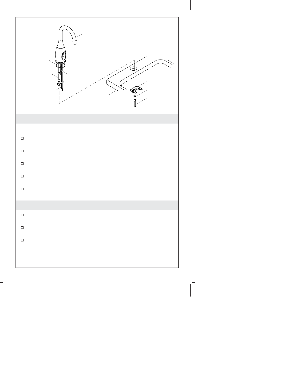
Place the handle in the vertical position, as shown.
Rotate the handle clockwise, then reposition the handle at the 2
o’clock position.
For hot and cold water supply installations: Rotate the handle as
needed to achieve the desired water temperature.
For tempered or filtered water installations: Turn the handle
counterclockwise to the full cold position.
Secure the cover and handle to the valve with two screws
(provided).
7. Troubleshooting
Symptoms Probable
Causes Recommended Action
1. No water
flow.
A. There is a
loose
connection.
A. Remove the valve cover and
check the connections from the
battery to the solenoid and
from the battery holder to the
sensor. Make sure that the
connector arrows are aligned
and that the connection is
secure.
B. The
supply
stops are
in the
″OFF″
position.
B. Confirm the supply stops are in
the ″ON″position.
C. The
wires/cables
are
pinched or
damaged.
C. Remove the cover and inspect
the wires/cables for cuts or
damage. If the wires are cut or
damaged, order a new
solenoid, sensor assembly,
sensor extension cable, or
battery holder. Do not pinch or
damage the wires during
reassembly.
1056542-2-B 10 Kohler Co.

Troubleshooting (cont.)
Symptoms Probable
Causes Recommended Action
D. There is
water
leakage on
electrical
components
or
connectors.
D. Remove the cover and check
for corrosion on the
connections between the
battery to solenoid and the
battery holder to the sensor. If
possible, clean the terminals. If
unable to repair the connection,
order a new sensor assembly,
battery holder, or solenoid
assembly, as required. Inspect
the gasket between the valve
body and spout hose for cuts,
debris, etc. If the gasket is
damaged, order a new gasket.
The origin of the leak must be
investigated and repaired.
E. The
battery life
has
expired.
E. Remove the cover and replace
the battery. The faucet requires
a standard 2CR5 6 V lithium
battery. This item is not
available from Kohler Co., but
can be purchased at retail
stores.
F. Sensor
eyes are
dirty.
F. Wipe the sensor eyes with a
damp soft cloth. Wipe dry with
a dry soft cloth.
G. Supply
pressure is
low.
G. Verify that the water supply is
turned on and that pressure is
at least 20 psi (137 kPa).
H. Incorrect
installation.
H. Verify that the faucet is
mounted flat to the deck
surface and that the sensor eyes
are aligned to the user area.
I. The filters
are
plugged.
I. Refer to the ″Service the Filters″
section of the Homeowners
Guide.
J. The
aerator is
plugged.
J. Remove the aerator and clean.
For calcium/mineral deposits,
soak the plastic insert in a 50:50
mix of water and vinegar. Soak
only the plastic insert.
K. Sensor
eyes are
scratched.
K. Replace the sensor assembly.
Kohler Co. 11 1056542-2-B

Troubleshooting (cont.)
Symptoms Probable
Causes Recommended Action
L. Hose is
kinked.
L. Check the hoses to make
certain they are not kinked. If
a hose is kinked, disconnect the
hose, straighten, then reconnect.
M. The
solenoid
does not
work.
M. Remove the valve cover and
solenoid. Replace the solenoid
as needed. Refer to the ″Test
and Service the Solenoid″
section of the Homeowners
Guide.
2. Low flow. A. Supply
pressure is
low.
A. Check filtration systems for
blockage. Check incoming
water pressure. Pressure should
be at least 20 psi (137 kPa).
B. The filters
are
plugged.
B. Refer to the ″Service the Filters″
section of the Homeowners
Guide.
C. The
aerator is
plugged.
C. Remove the aerator and clean.
For calcium/mineral deposits,
soak the plastic insert in a 50:50
mix of water and vinegar. Soak
only the plastic insert.
3. Constant
water flow.
A. The
diaphragm
seal is
dirty or
damaged.
A. Turn off the water supply and
purge the faucet. Remove the
cover and check the diaphragm
and surrounding area for
debris. Clean out any debris. If
the diaphragm is damaged,
order a replacement. Refer to
the ″Service the Diaphragm″
section of the Homeowners
Guide.
B. The
battery life
has
expired.
B. Remove the valve cover and
replace the battery. The spout
requires a standard 2CR5 6 V
lithium battery. This item is not
available from Kohler Co., but
can be purchased at retail
stores.
C. The
solenoid is
plugged.
C. Remove the valve cover and
solenoid. Check the solenoid
holes for debris.
1056542-2-B 12 Kohler Co.

Troubleshooting (cont.)
Symptoms Probable
Causes Recommended Action
D. The
solenoid
does not
work.
D. Remove the valve cover and
solenoid. Replace the solenoid
as needed. Refer to the ″Test
and Service the Solenoid″
section of the Homeowners
Guide.
E. The filters
are
plugged.
E. Refer to the ″Service the Filters″
section of the Homeowners
Guide.
4. Sporadic
water flow.
A. The wires
are
pinched or
damaged.
A. Remove the cover and inspect
the wires/cables for cuts or
damage. If the wires are cut or
damaged, order a new
solenoid, sensor assembly,
sensor extension cable, or
battery holder. Do not pinch or
damage the wires during
reassembly.
B. The
battery life
has
expired.
B. Remove the valve cover and
replace the battery. The spout
requires a standard 2CR5 6 V
lithium battery. This item is not
available from Kohler Co., but
can be purchased at retail
stores.
5. Sensor
flashes once
approximately
every 8
seconds. The
product
continues to
operate.
A. The
battery
power is
low.
A. Replace the battery. The
product may continue to
operate for several days with
low battery power. The product
requires a 2CR5 6 V lithium
battery. This item is not
available from Kohler Co. but
can be purchased at a local
retail store.
6. Sensor
flashes once
approximately
every 2
seconds. The
product does
not operate.
A. The
battery
power is
insufficient
to allow
the
product to
operate.
A. Replace the battery. The
product requires a 2CR5 6 V
lithium battery. This item is not
available from Kohler Co. but
can be purchased at a local
retail store.
Kohler Co. 13 1056542-2-B

Guide d’installation
Robinet de cuisine électronique
Outils et matériels
Merci d’avoir choisi la compagnie Kohler
Nous apprécions votre engagement envers la qualité Kohler. Veuillez
prendre s’il vous plaît quelques minutes pour lire ce manuel avant de
commencer l’installation. Ne pas hésiter à nous contacter en cas de
problème d’installation ou de performance. Nos numéros de téléphone
et notre adresse du site internet sont au verso. Merci encore d’avoir
choisi la compagnie Kohler.
Avant de commencer
ATTENTION : Risque d’endommagement du produit. Ce
produit contient des composants électroniques sensibles. Ne pas
entreposer les récipients de produits chimiques ou de nettoyage
près de ce produit. Les objets de nettoyage (tels que torchons ou
éponges) doivent être complètement rincés avec de l’eau fraîche
avant le stockage.
Respecter tous les codes de plomberie et de bâtiment locaux.
Couper l’alimentation d’eau principale.
Remettre le robinet dans son emballage de protection jusqu’à être
prêt à l’installation.
Pour une nouvelle pose, installer le robinet avant d’installer
l’évier.
Clé à
molette Tournevis à
rainures T d'alimentation de
3/8" avec arrêts
Plus:
Seau Colliers de serrage
• Qté: 2 - Vis/fixations à bois #8
Kohler Co. Français-1 1056542-2-B

Avant de commencer (cont.)
Ce robinet électronique est cataloguéà6VDC1Wetestopéré
avec une pile au lithium 2CR5 6V (fournie).
Ce robinet électronique est conçu pour utilisation avec un robinet
principal de cuisine. Ce guide d’installation est écrit pour ce type
de configuration.
REMARQUE : Dans les localités où l’eau a un haut niveau de
particules, installer le filtre d’eau de 20-microns sur la ligne
d’alimentation.
Si une alimentation unique d’eau mélangée ou filtrée est utilisée,
se référer à la section ″Convertir à de l’eau mélangée ou filtrée
(Optionnel)″de ce guide.
Kohler Co. se réserve le droit d’apporter toutes modifications au
design des robinets et ceci sans préavis, comme spécifié dans le
catalogue des prix.
Kohler Co. Français-2 1056542-2-B

1. Installer le robinet
REMARQUE : Si possible, installer le robinet avant d’installer
l’évier.
Glisser un joint torique sur le tuyau flexible, câble du capteur, et
le montant fileté. Positionner le joint torique dans la rainure à la
base du robinet.
Passer le tuyau flexible, le montant, et le câble du capteur dans
l’orifice de montage de l’évier.
Glisser le support, la rondelle, et l’écrou sur le montant fileté d’en
dessous de l’évier.
Bien serrer l’écrou contre le dessous de l’évier. Ne pas trop serrer
l’écrou.
Installer l’évier à ce stade. Se reporter aux instructions du
fabricant de l’évier.
2. Convertir à de l’eau mélangée ou filtrée (Optionnel)
Retirer le tuyau d’alimentation d’eau chaude du corps de
l’ensemble du corps de valve avec une clé.
Couvrir l’entrée d’alimentation d’eau chaude de l’ensemble du
corps de valve avec un bouchon (fourni). Serrer le bouchon avec
une clé.
Ouvrir en position froide le mélangeur du corps de la valve.
Joint torique
Robinet
Support
Rondelle
Écrou
Évier
Montant
fileté
Câble capteur
Tuyau flexible
1056542-2-B Français-3 Kohler Co.

3. Monter l’ensemble du corps de valve
ATTENTION : Risque de restriction du débit d’eau et
d’endommagement du produit. Faire extrêmement attention afin
d’éviter de plier ou coincer les tuyaux d’alimentation. Les
flexibles ne doivent pas être tendus pendant l’installation. Si les
tuyaux d’alimentation doivent être embobinés, maintenir une
boucle intérieure de 3″(7,8 cm).
ATTENTION : Risque d’endommagement du matériel. Faire
attention durant l’installation afin d’éviter le contact avec des
câbles, tuyaux, appareils, ou autres objets pouvant être derrière
la surface de montage. La méthode de fixation ne doit pas
présenter un risque aux emplacements adjacents, tels que vis
exposées. Fournir une méthode adéquate de fixation de la valve
au mur ou au meuble.
REMARQUE : L’ensemble du corps de valve doit être installé
verticalement.
REMARQUE : Lors de la considération d’emplacement de
l’ensemble du corps de valve, sélectionner un endroit permettant un
dégagement adéquat pour le service de la pile et un accès à la
poignée pour le contrôle de température.
REMARQUE : L’ensemble du corps de valve devrait être monté
avec deux vis à bois #8 (non-fournies) ou autres fixations adéquates
(non-fournies) basées sur le type et l’épaisseur du meuble ou du
matériau du mur.
Joint
Ensemble
corps de
valve
Vis et
fixations
Kohler Co. Français-4 1056542-2-B

Monter l’ensemble du corps de valve (cont.)
Attacher l’ensemble du corps de valve au meuble.
1056542-2-B Français-5 Kohler Co.

4. Installer la pile
ATTENTION : Risque d’endommagement du produit. Vérifier
que le câble solenoïde et le câble du capteur ne sont pas pincés
durant l’assemblage.
Positionner le câble du capteur à partir du robinet dans la base
du compartiment à piles.
Connecter le câble du capteur à partir du robinet au connecteur
femelle dans le compartiment à piles.
Insérer la pile dans le compartiment à piles avec le rebord
concave orienté vers le compartiment, puis fermer le clip de la
pile.
Connecter le connecteur du compartiment à piles au connecteur
solénoïde avec les flèches orientées les unes vers les autres.
Connecter le compartiment à piles à l’ensemble du corps de
valve.
Support pile
Support
pile
Clip de la pile
Pile
Connecter avec les flèches les
unes vers les autres.
Ensemble
corps de
valve
Connecteur
compartime
nt à piles
Connecteur
solénoïde
Câble capteur
Kohler Co. Français-6 1056542-2-B

5. Connecter les alimentations
ATTENTION : Risque de restriction du débit d’eau et
d’endommagement du produit. Faire extrêmement attention afin
d’éviter de plier ou coincer les tuyaux d’alimentation. Les
flexibles ne doivent pas être tendus pendant l’installation. Si les
tuyaux d’alimentation doivent être embobinés, maintenir une
boucle intérieure de 3″(7,8 cm).
ATTENTION : Risque d’endommagement du produit. Vérifier
que le connecteur solénoïde et le câble du capteur ne sont pas
pincés lors de la connexion aux alimentations.
IMPORTANT ! Pour assurer une bonne performance au robinet, les
lignes d’alimentation doivent être purgées avant de procéder à
l’installation.
Ouvrir l’alimentation d’eau principale.
Ouvrir les arrêts d’alimentation en position ″ON″.
Purger l’eau des arrêts d’alimentation et dans un seau pour retirer
tous débris.
Fermer les arrêts d’alimentation en position ″OFF″.
Connecter les tuyaux d’alimentation aux T avec les arrêts
d’alimentation.
IMPORTANT ! S’assurer que le joint est en place entre le tuyau
flexible et la sortie de l’ensemble du corps de valve.
Tuyau flexible
Joint
Ensemble
corps de
valve T d'alimentation de
3/8" avec arrêts
1056542-2-B Français-7 Kohler Co.
This manual suits for next models
1
Table of contents
Languages:
Other Kohler Household Appliance manuals