Tools and Materials
Before You Begin
IMPORTANT! When using this unit, basic precautions should always be followed.
DANGER: Risk of electrocution. Disconnect the electricity to the working area at the main breaker
panel before performing these installation steps.
WARNING: Risk of personal injury. If you become uncomfortable while taking a steam bath, you
should power off the unit. Cool off with the shower, open the door, or exit the unit.
WARNING: Risk of allergic reaction. Before adding any oils, aromatic therapies, or skin care
products to the aromatherapy well, make sure they will not cause an allergic reaction to the user.
WARNING: Risk of personal injury. This steam bath may not be suitable for use if you are
pregnant, have a heart condition, have high blood pressure, have circulatory problems, are under
the influence of alcohol, are taking drugs or are under the care of a physician. A steam bath can put
undue stress on the body, as does any hot bath, shower, or sauna.
WARNING: Risk of personal injury. DO NOT consume alcoholic beverages or take
medications/drugs prior to or when using the steam bath. Alcohol and drugs affect mental
judgement and inhibit bodily functions such as heartbeat and respiration, resulting in potentially
dangerous effects.
WARNING: Risk of injury to children. Do not allow children to use this unit unless they are
closely supervised at all times. The steam generator is not designed to be used by children.
WARNING: Risk of scalding. Do not block the steam head or locate it near a seat or bench, as the
steam head is hot during operation and may scald the user if touched.
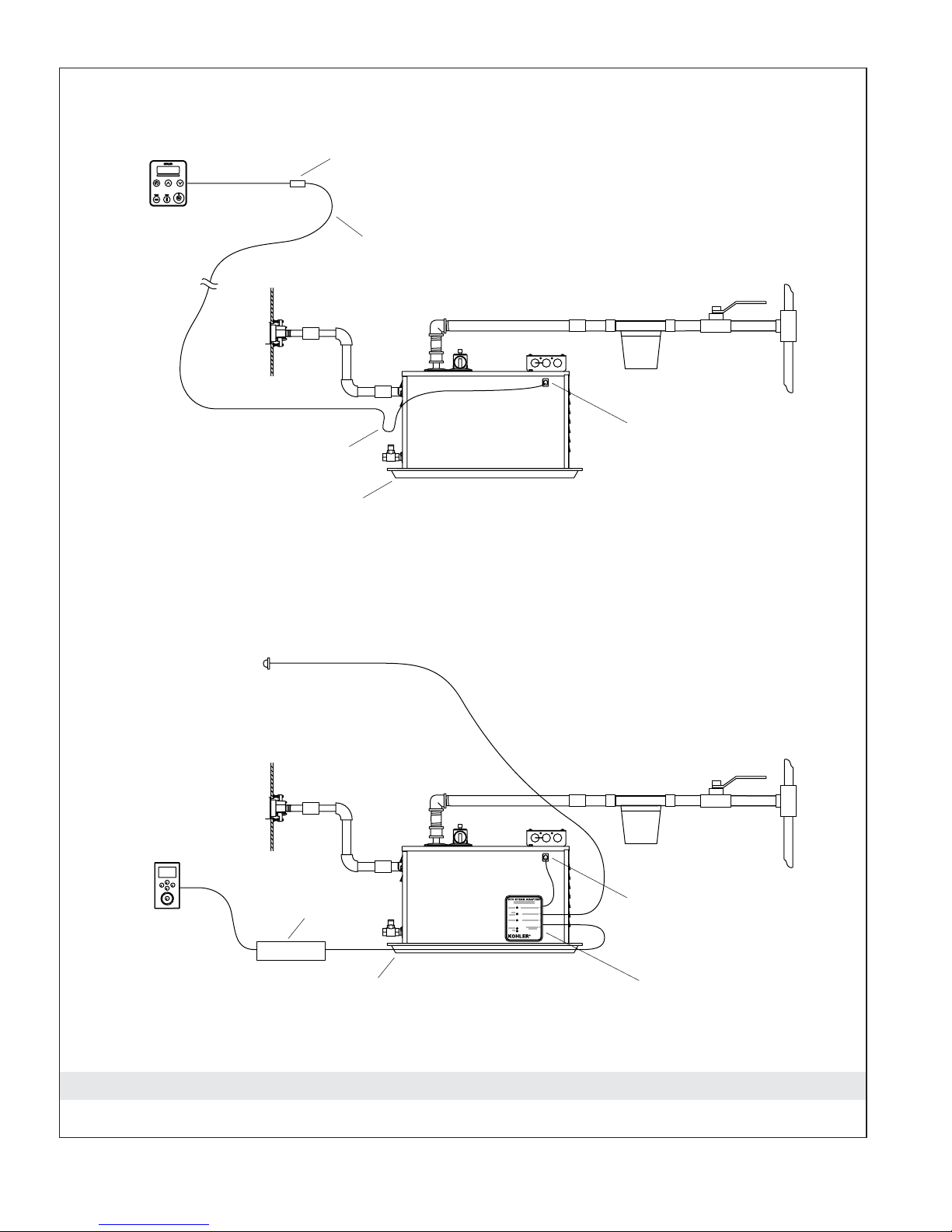
WARNING: Risk of property damage. Allow a minimum of 12″(30.5 cm) of air space around the
steam generator at all times. This provides an area for the heat generated by the unit to dissipate.
WARNING: Risk of personal injury or property damage. Do not direct the pressure relief valve to
the enclosure. In the event the pressure relief valve activates, the hot water may spray causing
burns to the user and/or damage to the enclosure. Therefore, the pressure relief valve should be
directed to an area where damage will not occur from contact with hot water and conform to
national and local plumbing codes.
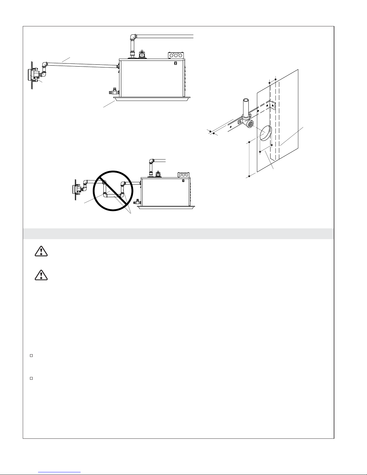
WARNING: Risk of personal injury. Do not plumb a trap in the steam line or plumb the pressure
relief valve into the steam line. Plumbing the pressure relief valve into the steam line can be
hazardous if the steam outlet is capped.
Hacksaw or Tube Cutter Screwdrivers Tape
Measure
Solder
Drill w/ 1-1/4" &
2-1/2" Hole Bit
Adjustable
Wrench
Propane
Torch
• Drain/spill pan
• 1/2" copper tubing
• Assorted copper fittings
•1/2" & 3/4" NPT unions
• Conventional woodworking tools
and materials
Plus:
Sealant
Tape
1060226-2-E 2 Kohler Co.