Before You Begin (cont.)
directed to an area where damage will not occur from contact with hot water and conform to
national and local plumbing codes.
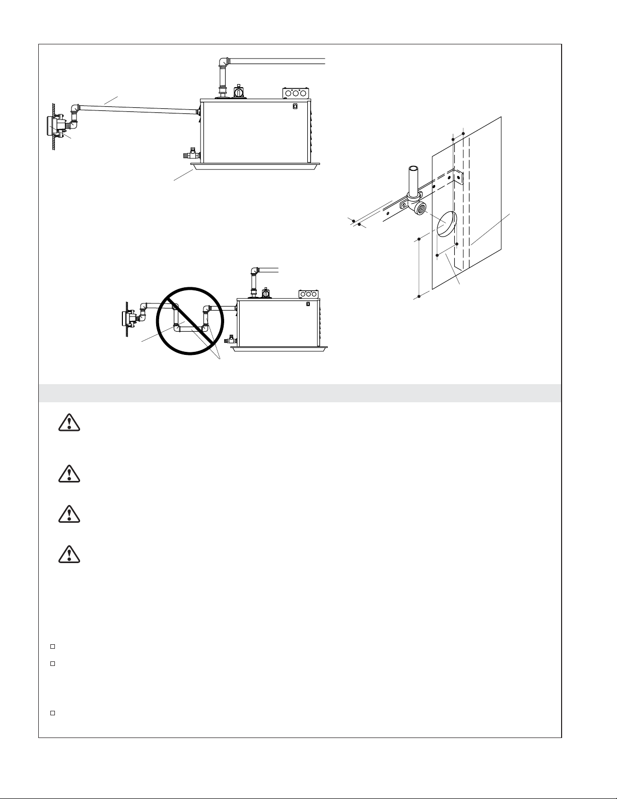
WARNING: Risk of personal injury. Do not plumb a trap in the steam line or plumb the pressure
relief valve into the steam line. Plumbing the pressure relief valve into the steam line can be
hazardous if the steam outlet is capped.
CAUTION: Risk of scalding hazard. Any variance in settings or water inlet conditions from those
used during the factory calibration may raise the discharge temperature about the safe limit and
may present a scalding hazard. This device has been calibrated at the factory to ensure a safe
maximum water temperature. Responsibility for installation and adjustment of this device in
accordance with these instructions lies with the installer.
CAUTION: Risk of product damage. Use copper or brass fittings only. Iron fittings or pipes will
rust and discolor the floor and walls of the steam enclosure.
IMPORTANT! Use this unit only for its intended use as specified in this manual. DO NOT use
attachments not recommended by Kohler Co.
IMPORTANT! It is not recommended that you use the whirlpool and the steam unit at the same time
when they are both installed.
Follow all local plumbing and electrical codes. All electrical work should be done by a licensed
electrician.
Do not install a GFCI to this unit. This will prevent nuisance tripping.
Disconnect all power before making any electrical connections.
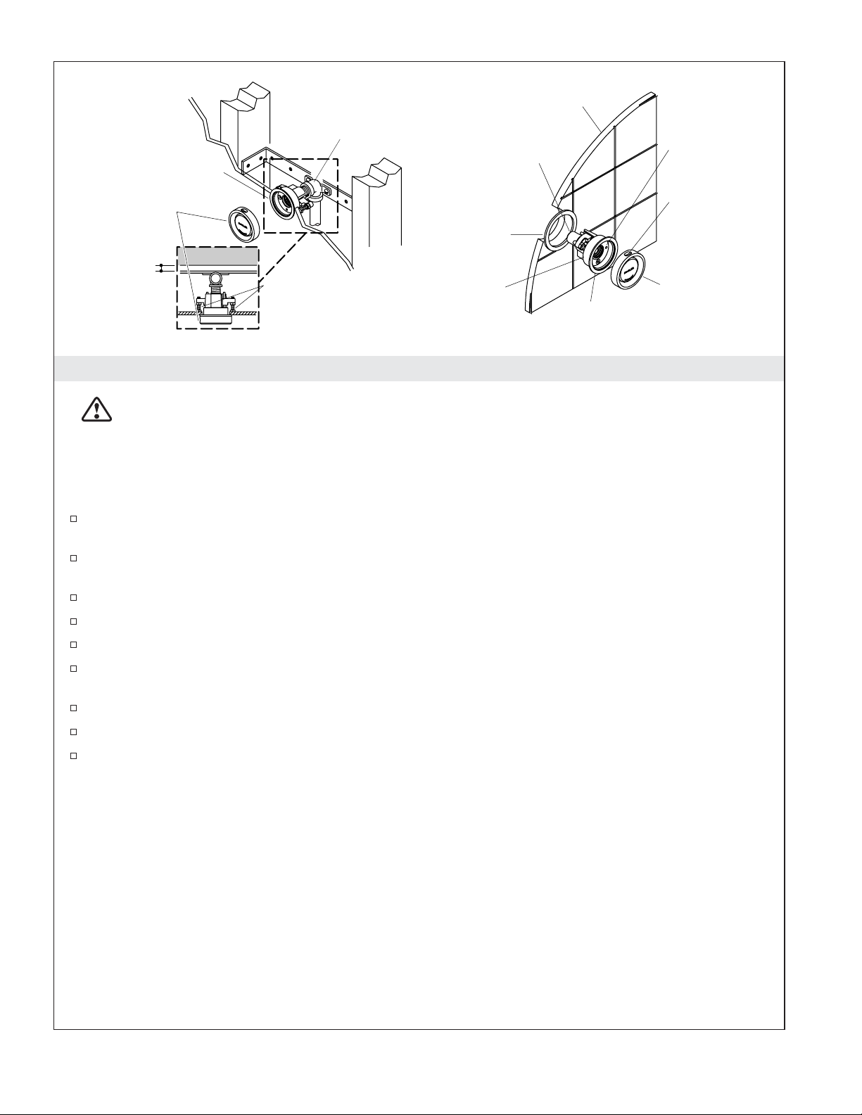
Ensure the enclosure to be used is vapor proof. The enclosure should have vapor proof door seals to
ensure steam does not escape. The walls and ceiling should be constructed of a material that will
not be damaged by steam and hot condensation.
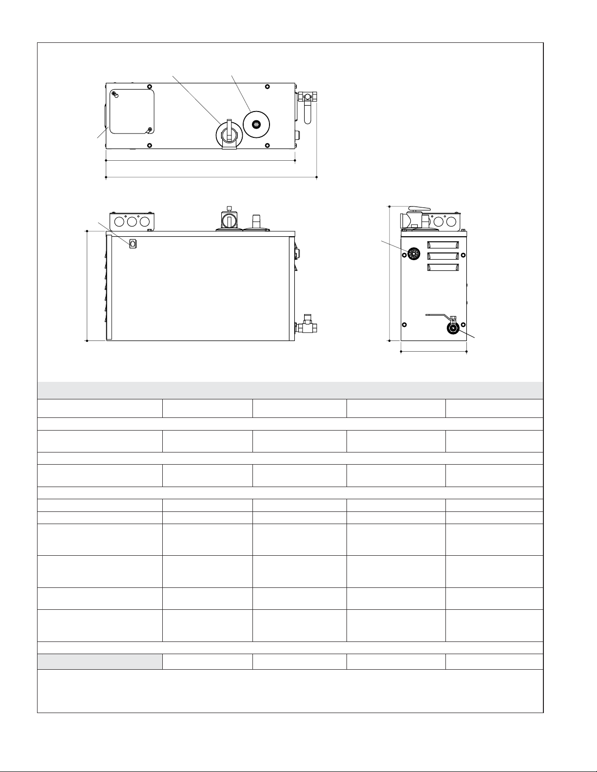
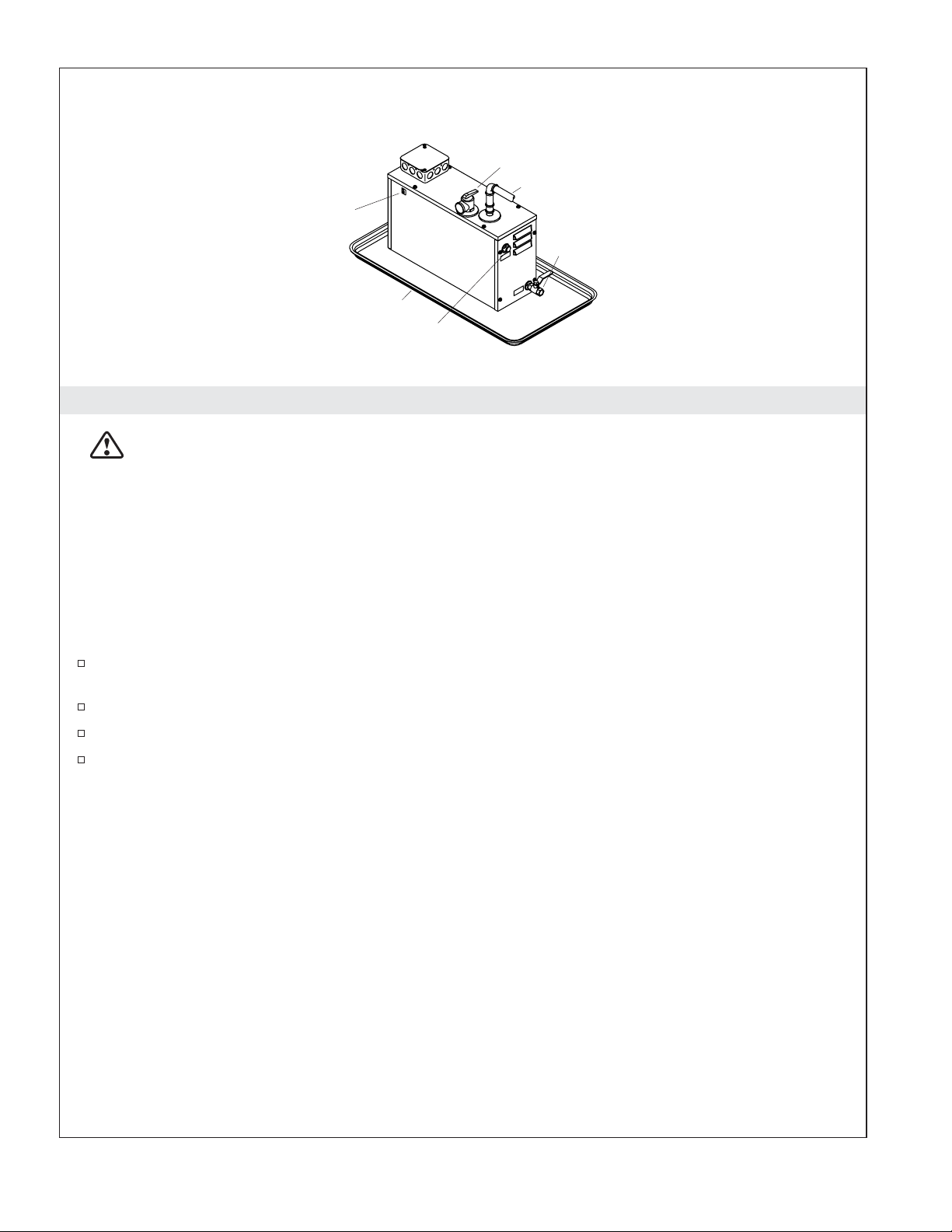
The water inlet, steam outlet, and pressure relief valves should be brass unions for easy removal.
Install a drain/spill pan under the unit.
The generator must be upright, accessible, and on a level surface. The access panel and drain valve
must be unobstructed and allow for easy access.
The steam generator may be installed up to 25 ft. (7.62 m) away from the steam head in a dry,
well-ventilated area.
The required service access for the steam generator must be 20″(50.8 cm) in height and 13″(33 cm)
in width.
An in-line water filter is recommended to decrease the chance of blockage within the steam
generator and increase the life expectancy of the steam generator.
Pitch the steam line toward the generator and avoid perfectly level lines.
Make sure the water is turned on to the unit and the drain is in the closed position before operating
the unit.
Before connecting the water line to the generator, flush the water line into a five gallon pail to
remove any silt or other materials that may be in the line.
NOTE: For service and installation issues and concerns, call 1-800-585–STEAM (7832).
Kohler Co. reserves the right to make revisions in the design of products without notice, as specified
in the Price Book.
Kohler Co. 3 1008019-2-J