2
1313992-T01-A
TOOLS AND MATERIALS
IMPORTANT SAFETY INSTRUCTIONS
This product complies with IEC EN 60335-2-53:2011 and EN 60335-1:2012/A11:2014.
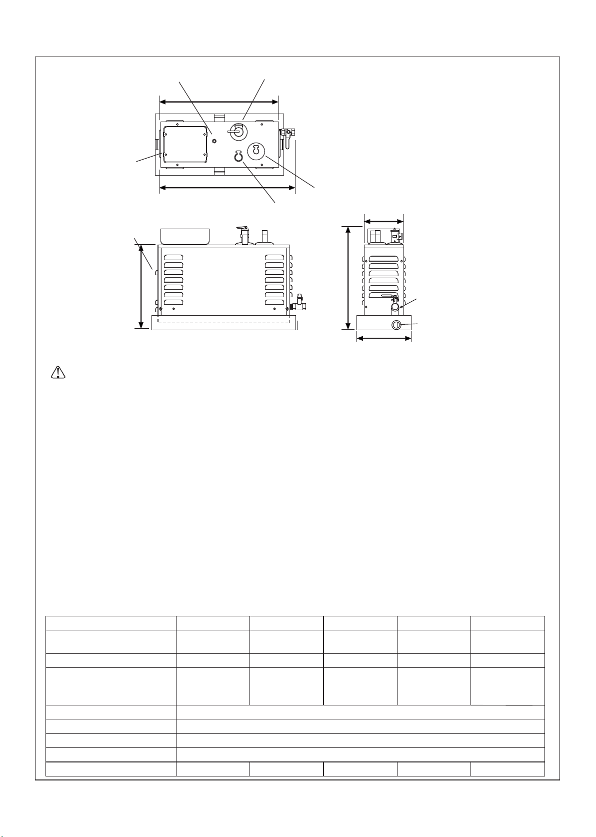
Water Pressure: 0.14MPa~0.55MPa
IMPORTANT! When using this unit, basic precautions should always be followed.
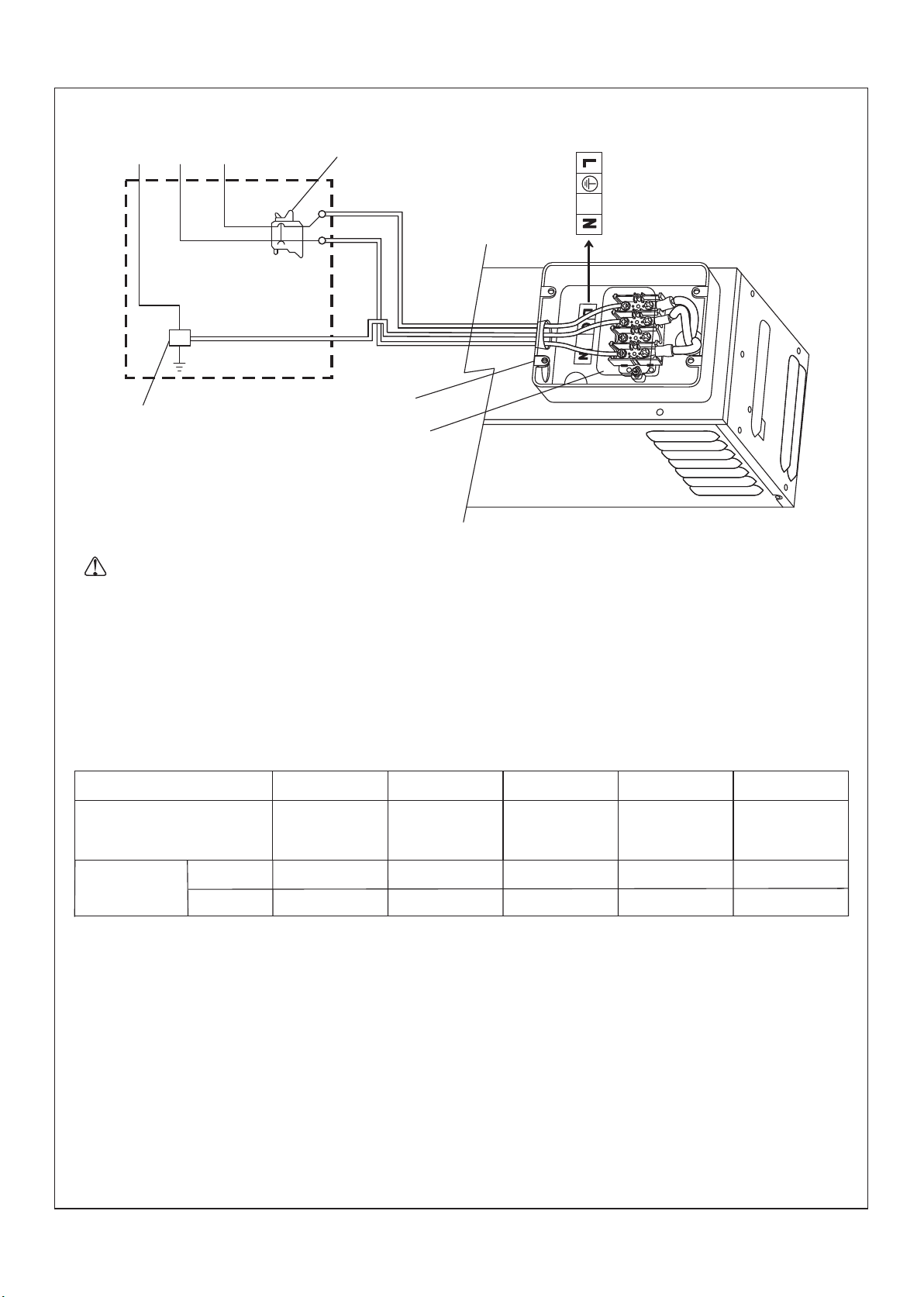
DANGER: Risk of electrocution. Disconnect the electricity to the working area at the main breaker panel
before performing these installation steps.
WARNING: Risk of personal injury. If you become uncomfortable while taking a steam bath, you should
power off the unit. Cool off with the shower, open the door, or exit the unit.
WARNING: Risk of allergic reaction. Before adding any oils, aromatic therapies, or skin care products to
the aromatherapy well, make sure they will not cause an allergic reaction to the user.
WARNING: Risk of personal injury. This steam bath may not be suitable for use if you are pregnant, have
a heart condition, have high blood pressure, have circulatory problems, are under the influence of alcohol,
are taking drugs or are under the care of a physician. A steam bath can put undue stress on the body, as
does any hot bath, shower, or sauna.
WARNING: Risk of personal injury. The wet surfaces of steam enclosures may be slippery. Use care
when entering or leaving.
WARNING: Risk of personal injury. Prolonged use of the steam system can raise excessively the internal
human body temperature and impair the body’s ability to regulate its internal temperature (hyperthermia).
The appliance is to be continuously attended. Limit your use of steam to 10-20 minutes until you are certain
of your body’s reaction.
WARNING: Risk of personal injury. DO NOT consume alcoholic beverages or take medications/drugs
prior to or when using the steam bath. Alcohol and drugs affect mental judgement and inhibit bodily
functions such as heartbeat and respiration, resulting in potentially dangerous effects.
WARNING: Risk of injury to children. This appliance can be used by children aged from 8 years and
above and persons with reduced physical, sensory or mental capabilities or lack of experience and
knowledge if they have been given supervision or instruction concerning use of the appliance in a safe way
and understand the hazards involved. Children shall not play with the appliance. Cleaning and user
maintenance shall not be made by children without supervision.
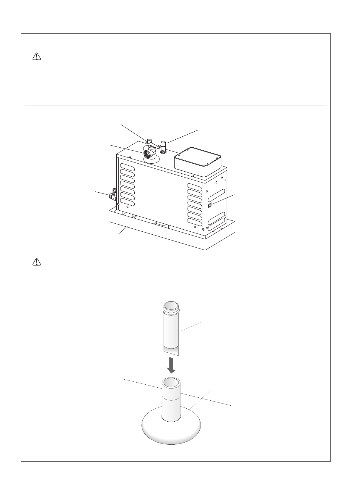
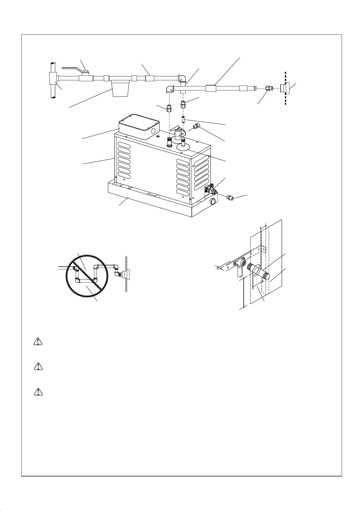
WARNING: Risk of personal injury. Do not plumb a trap in the steam line or plumb the pressure relief
valve into the steam line. Plumbing the pressure relief valve into the steam line can be hazardous if the
steam outlet is capped.
WARNING: Risk of scalding. Do not touch the steam head during operation. The steam head is hot during
operation.
WARNING: Risk of personal injury. HYPERTHERMIA occurs when the internal temperature of the body
reaches a level several degrees above the normal body temperature of 37°C. The symptoms of
hyperthermia include an increase in the internal temperature of the body, dizziness, lethargy, drowsiness,
and fainting. The use of alcohol, drugs, or medication can greatly increase the risk of hyperthermia.
WARNING: Risk of personal injury or property damage. Avoid coming in contact with the water tank
and/or steam discharge line while the generator is operating or shortly after shutdown. Wear eye protection
and protective clothing when servicing the steam generator. The steam generator operates at high
temperatures.
WARNING: Risk of personal injury or property damage. DO NOT install the heating apparatus in the
steam enclosures.
NOTICE: If any heating apparatus(electric stove, bath heater etc.) is installed in the shower enclosure and both
the heater and steam generator is activated at the same time, the steam generator may malfunction due to heat of
the heating apparatus. Also, the heating apparatus could malfunction or be out of the order by steam of steam
generator.
Plug:
·1/2" copper tubing
·Assorted copper fittings; G3/8", G1/2" and G3/4" copper
unions
·Wire Cutters or Wire Strippers
·Conventional woodworking tools and materials
·45 and 90 degree elbows
·Support Blocks (heat resistant)
Hacksaw or
Tube Cutter
Drill w/ 1-1/4" &
2-1/2" Hole Bit Sealant Tape Solder Propane Torch