CAUTION: Risk of personal injury or product
damage.
IMPORTANT!
IMPORTANT!
NOTE:
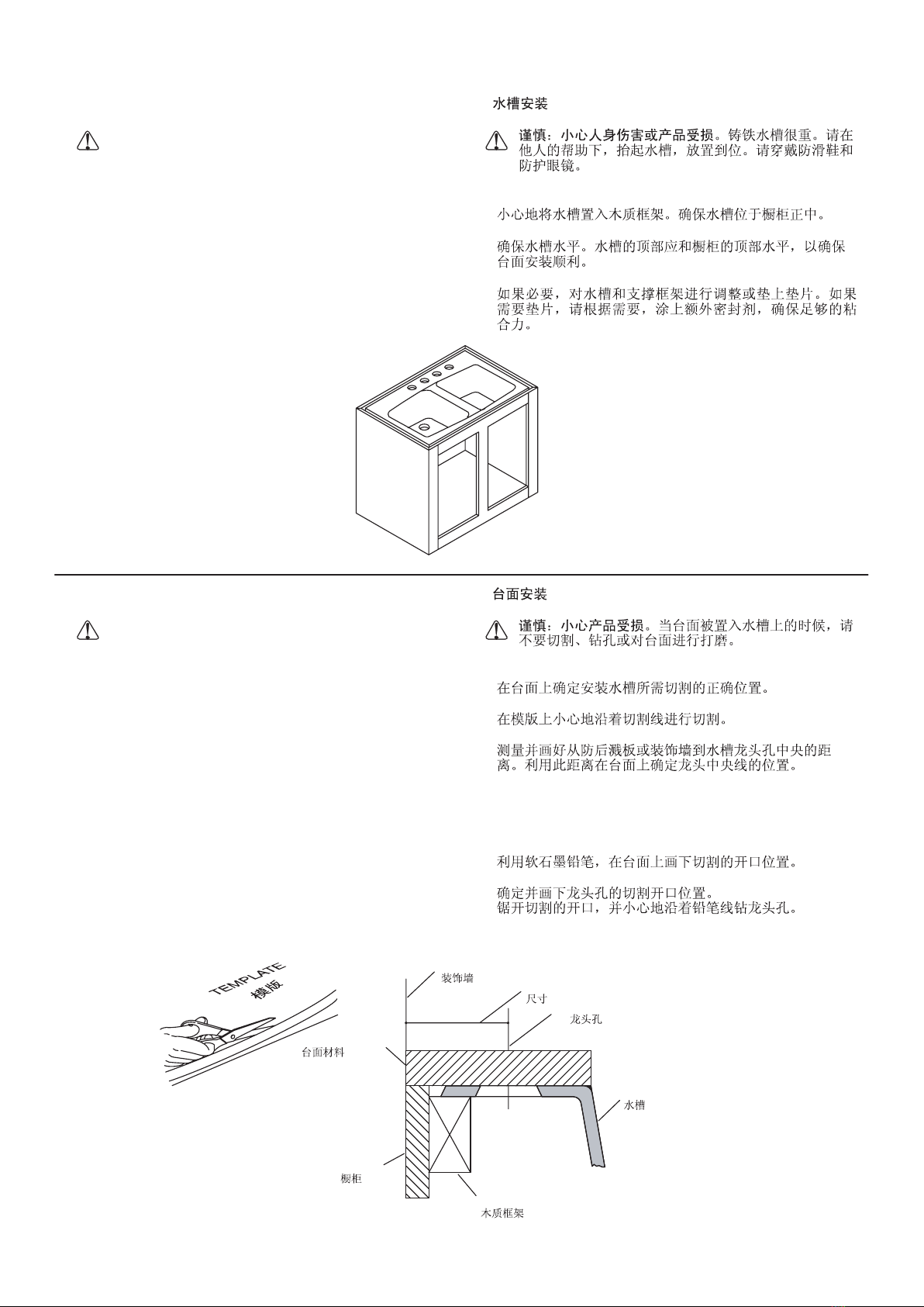
Do not support the sink by the sink rim. The
support framing, not the rim, should withstand the
entire weight of the sink when it is full of water.
Inspect the flooring at the installation site.
Repair as necessary.
Make sure there is adequate plywood
support if the floor is constructed of wood.
You may require different or more specialized tools to
install this sink to countertop materials other than wood or
wood composites.
!
!
!
!
A.
A. Prepare the Site
2.
2. UNDERCOUNTER INSTALLATION
-3-
!
!
!
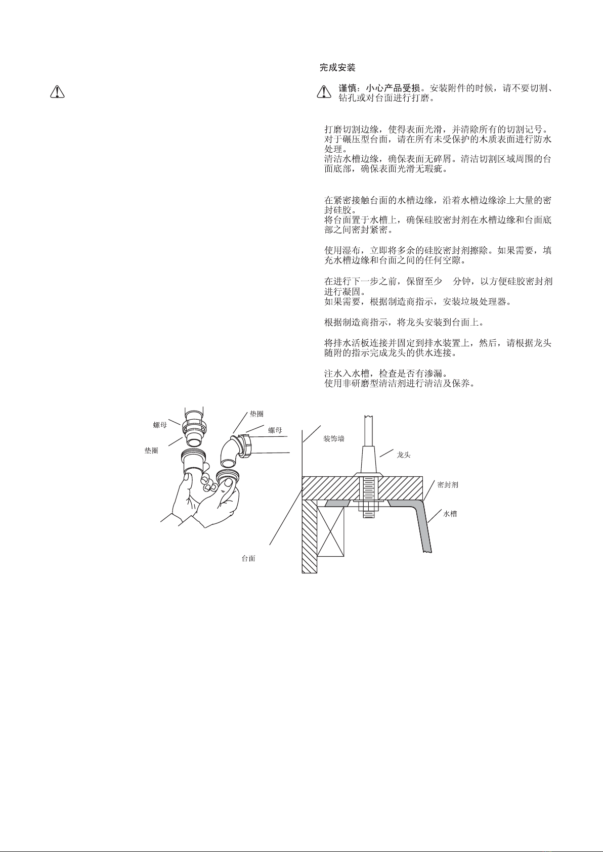
Measure the thickness of the countertop.
Determine the threaded shank length of the faucet.
Measure to verify that the faucet will fit on the countertop
as required. If the faucet will not fit, you will need to select
a different faucet or countertop.
!
!
!
Countertop Thickness
Faucet Assembly
NOTE: This cast iron sink requires either an undermounter
bracket(not supplied) or support framing. Undermounter
bracket installation is covered in this section. Support framing
is covered in the Install the Support Frame section.
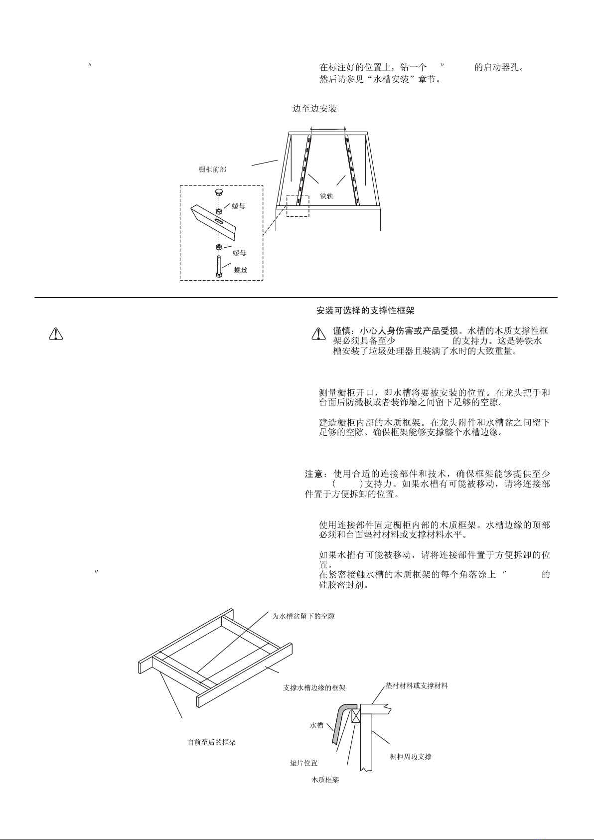
Determine the left-to-right length of the inside of the
cabinet.
If necessary, cut the bracket rails so they fit snugly with
the cabinet walls. Rails may be up to 1/8 (3 mm) shorter
than the determined length of the cabinet.
Thread the bolts into the nuts two turns, and then slide the
nuts into the slot in the rails. Slide the nut and bolt into the
desired position in the slots located on the rails. Adjusting
bolts should be located in the outermost slots that will be
under the corners of the sink.
With a tape measure, determine the overall width of your
sink. This distance represents the distance (A) between
the outside edges of the rails, as shown in the schematic
above.
Using a hanger bracket as a template, mark the screw
placement on the cabinet, according to the measured
width of your sink.
“”
!
!
!
!
!
!
!
!
!
!
1/8 (3mm)
A
B.
B. Install the Optional Undermounter Kit
1067482-T01-A