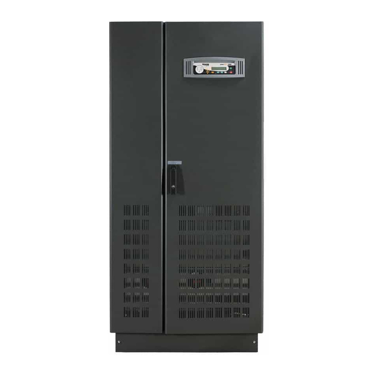
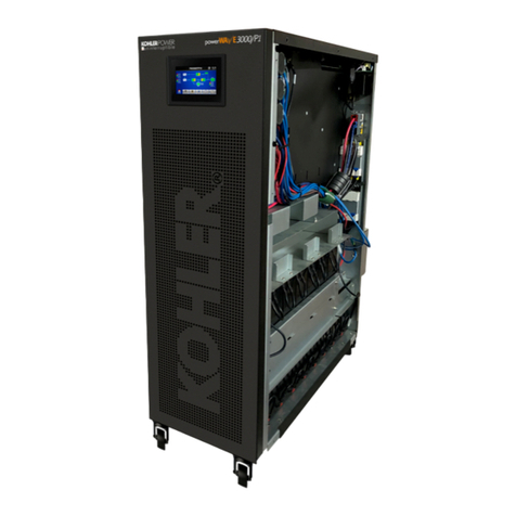
Kohler PW 6000 User manual

User Manual
KOHLER PW 6000
Medium to high power three-phase uninterruptible power supply
(400-500 kVA)

© 2023 Kohler Uninterruptible Power 12/9/23
Document Control
Useful Contacts
All product, product specifications and data are subject to change without notice to improve reliability, function, design or otherwise.
Kohler Uninterruptible Power has taken every precaution to produce an accurate, complete and easy to understand specification
document and will assume no responsibility nor liability for direct, indirect or accidental personal or material damage due to any
misinterpretation of, or accidental errors, in this manual.
© 2023 Kohler Uninterruptible Power
This manual may not be copied or reproduced without written permission of Kohler Uninterruptible Power
ISSUE DATE REVISION SUMMARY
TS_830_01 21/08/2023 Rebranding to KUP International Version
UK
www.kohler-ups.co.uk Kohler Uninterruptible Power web site
ukservice.ups@kohler.com Service department – booking service, fault reporting etc.
uktechnicalsupport.ups@kohler.com Technical queries
uksales.ups@kohler.com Hardware sales
ukservicesales.ups@kohler.com Extended warranty agreements etc
IRELAND
www.kohler-ups.ie Kohler Uninterruptible Power web site
ieinfo.ups@kohler.com Service department, technical queries, hardware sales and extended
warranty agreements
SINGAPORE
www.kohler-ups.sg Kohler Uninterruptible Power web site
salesups.sg@kohler.com Hardware sales
serviceups.sg@kohler.com Contract customer support, maintenance contracts renewals

© 2023 Kohler Uninterruptible Power 12/9/23
Document Control 1
Useful Contacts 1
1: Safety 1
1.1 Description of symbols used in this manual 1
1.2 User precautions 1
2: General Description 2
2.1 Introduction 2
2.1.1 Reliability and quality standards 2
2.1.2 Key features 2
2.2 KOHLER PW 6000 (400-500kVA) model range 3
2.3 UPS module functional description 4
2.3.1 UPS module block diagram 4
2.3.2 UPS internal operating modes 5
2.3.3 System operating modes 7
2.4 Multi-module parallel system 8
2.4.1 Parallel system concept 8
2.4.2 Parallel control functions 8
2.4.3 Common battery 10
2.5 Module Control Panel (standard LCD) 11
2.5.1 Module mimic LED indicators 11
2.5.2 Operator buttons 12
2.5.3 Power Management Display (PMD) 13
2.6 TFT Module control panel 15
2.6.1 Display header bar 15
2.6.2 Mimic diagram screen 16
2.6.3 Home screen 17
2.7 Warranty 19
2.8 Extended Warranty 19
2.9 Contacting service 19
3: Installation 20
3.1 Introduction 20
3.2 Taking receipt of the UPS 20
3.2.1 Reporting transportation damage 20
3.2.2 Local transportation 21
3.2.3 Storage 21
3.3 Unpacking 21
3.4 Planning the installation (environmental and mechanical) 21
3.4.1 Environmental considerations 21
3.4.2 UPS Cabinet installation 22
3.4.3 Top Cable Entry (TCE) extension cabinet installation 22
3.4.4 Battery installation 24
3.5 Planning the installation (cabling considerations) 24
3.5.1 General requirements 24
3.5.2 Parallel cabinet cabling recommendations 25
3.5.3 External maintenance bypass switch 26
3.5.4 Cable sizing 27
3.6 Electrical installation (cabling procedures) 28
3.6.1 Bottom entry cabling procedure 29
3.6.2 Top entry cabling procedure 32
3.6.3 Connecting the battery 35
3.7 Single/Dual feed conversion 36
3.8 Installation of remote monitoring and control facilities 37
3.8.1 Module communications interface facilities 37
4: Operating Instructions (LCD) 38

© 2023 Kohler Uninterruptible Power 12/9/23
4.1 Introduction 38
4.1.1 Commissioning 38
4.1.2 Operating procedure summary 38
4.1.3 General warnings and precautions 39
4.2 How to start the UPS system from a fully powered-down condition 39
4.3 How to start the UPS system from the maintenance bypass 41
4.4 How to transfer the load to maintenance bypass 41
4.5 How to shut down the complete UPS system 42
4.6 Operating in bypass (ECO) mode 43
4.6.1 How to Turn ON the UPS system and operate in ‘on bypass’ (ECO) mode 43
4.6.2 How to Turn OFF the UPS system when operating in ‘on bypass’ (ECO) mode 43
4.6.3 How to transfer between ‘on bypass’ (ECO) and ‘on inverter’ mode 43
5: Operating Instructions (TFT) 44
5.1 Introduction 44
5.1.1 Commissioning 44
5.1.2 Operating procedure summary 44
5.1.3 General warnings and precautions 45
5.2 How to turn on the UPS system from a fully powered-down condition 46
5.2.1 Power-up the load on the maintenance bypass: 46
5.2.2 Transfer the load to the static bypass line: 47
5.2.3 Transfer the load to inverter: 48
5.3 How to start the UPS system from the maintenance bypass 49
5.3.1 Power up the UPS system: 49
5.3.2 Transfer the load to the static bypass line: 50
5.3.3 Transfer the load to inverter: 50
5.4 How to transfer the load to the maintenance bypass and turn OFF the UPS 50
5.4.1 Transfer the load to the static bypass: 51
5.4.2 Transfer the load to the maintenance bypass: 52
5.4.3 Turn OFF the UPS 52
5.5 How to shut down the complete UPS system 52
5.6 Operating in bypass (ECO) mode 53
5.6.1 How to Turn ON the UPS system and operate in (ECO) mode 53
5.6.2 How to transfer the load to the maintenance bypass and Turn OFF the UPS system 53
5.6.3 How to transfer between ‘on bypass’ (ECO) and ‘on inverter’ mode 53
6: Maintenance 54
6.1 Introduction 54
6.2 User responsibilities 54
6.3 Battery testing 54
7: Troubleshooting 55
7.1 Alarms 55
7.2 LCD Control panel 55
7.3 TFT Control panel 55
7.4 Troubleshooting table 56
7.5 Contacting service 56
8: Options 57
8.1 Introduction 57
8.2 Serial RS232 Computer interface – USB & JD1 (Smart Port) 58
8.3 RS485 Interface for multidrop – JR2 58
8.4 Dry ports customer interface (X1, X2, X3) 59
8.4.1 Dry port connections 59
8.4.2 Remote Emergency Power Off (EPO) option 60
8.4.3 Generator ON facilities 60
8.5 SNMP Card slots 61

© 2023 Kohler Uninterruptible Power 12/9/23
9: Specification 62

© 2023 Kohler Uninterruptible Power 12/9/23 1
1Safety
1.1 Description of symbols used in this manual
1.2 User precautions
WARNING: The warning symbol is used where there is danger of an electrical shock, equipment damage or
personal-injury.
CAUTION: The caution symbol is used to highlight important information to avoid possible equipment
malfunction or damage.
WARNING: Keep this manual with the UPS for future reference.
WARNING: The UPS and peripheral equipment must be installed and commissioned by suitably qualified and
trained personnel who are aware of the potential shock hazards.
WARNING: Do not attempt to install this UPS system until you are satisfied that ALL the safety instructions and
hazard warnings contained in this manual are read and fully understood.
WARNING: High leakage current!
Ensure that the UPS has been correctly earthed before you connect the mains power supply!
WARNING: This UPS must not be started-up or put into use without having first been commissioned by a fully
trained engineer authorised by the manufacturer.
WARNING: This UPS must be serviced by qualified personnel.
You run risk of exposure to dangerous voltages by opening or removing the UPS-covers! Kohler Uninterruptible
Powerwill assume no responsibility nor liability due to incorrect operation or manipulation of the UPS.
WARNING: The Kohler PW 6000 (400-500kVA) is a Class A UPS product (according to EN 62040-3). In a
domestic environment the UPS may cause radio interference. In such an environment the user may be required
to undertake additional measures.

2© 2023 Kohler Uninterruptible Power 12/9/23
2General Description
2.1 Introduction
Congratulations on your purchase of the KOHLER PW 6000 (400-500kVA) UPS.
Continuous power availability is essential in today’s dynamic IT and process-related work environments. It is equally
important that any installed power protection system is sufficiently resilient and adaptable to handle any requirement
changes brought about by the introduction of new server technologies, migration and centralization.
Such demands are well met by the KOHLER PW 6000 (400-500kVA) UPS system, which provides the foundation for
continuous power availability of network-critical infrastructures both in enterprise data centres, where business continuity
has paramount importance, and in process control environments, where manufacturing continuity is essential.
2.1.1 Reliability and quality standards
The KOHLER PW 6000 (400-500kVA) UPS is available over a model range of 400kVA to 500kVA and incorporates the
latest technological developments in power engineering. Representing a completely new generation of high power three
phase UPS systems, its advanced double conversion VFI (Voltage and Frequency Independent) topology responds fully
to both the highest availability and environmentally friendly requirements compliant with IEC 62040-3 (VFI-SS-111)
standards.
Kohler Uninterruptible Power specialises in the installation and maintenance of Uninterruptible Power Systems; and this
powerful UPS is just one example of our wide range of state-of-the-art power protection devices that will provide your
critical equipment with a steady and reliable power supply for many years.
2.1.2 Key features
High reliability, upgrade-ability, low operating costs and excellent electrical performance are just some of the highlights
afforded by this innovative UPS solution. Other key features include:
•Compact size, small foot print – Saving on expensive floor space
•Flexible battery management – Advanced management of battery charging and preventive failure diagnostics
avoids premature deterioration of battery life
•Best in class AC-AC efficiency, up to 96% – Saving on energy and operational cost (TCO)
•Low input power factor (near unity) – Saving cabling and supply distribution costs during installation and the over
the entire life cycle (TCO)
•Blade-server-friendly power – Full power available from 0.9 lead to 0.9 lag means that no de-rating is required with
leading power factor loads and therefore no need to ‘over-size’ the UPS system to cater for the load.
•Very low input current distortion THDi – The THDi is <3.5% @ 100% load, reducing the capital and installation
costs of an optional standby generator if used.
•Ease of expansion – Additional UPS cabinets (up to a maximum of 10) can be connected to an existing parallel
system without needing to disturb the load supply

© 2023 Kohler Uninterruptible Power 12/9/23 3
2: General Description
2.2 KOHLER PW 6000 (400-500kVA) model range
The KOHLER PW 6000 (400-500kVA) UPS line-up includes models ranging from 160 kVA up to 500 kW. This manual is
specific to the 400 kW and 500 kW models. A detailed specification can be found in Chapter 8.
Figure 2.1 KOHLER PW 6000 (400-500kVA) Model range
A key-lockable door is fitted to the front of the cabinet to provide controlled access; and within the cabinet all the major
power components are housed behind secured safety panels to further reduce the risk of accidental electrical shock.
The KOHLER PW 6000 (400-500kVA) UPS can be used as a single, stand-alone UPS module or up to ten modules can
be configured to operate as a parallel UPS system. A multi-module system is designed to increase the UPS system’s
output capacity and enhance the system’s reliability by providing module redundancy.
Note: In this manual the terms ‘multi-module system’ and ‘parallel system’ are synonymous.
MECHANICAL DETAILS STANDARD + TOP CABLE ENTRY (TCE)
CABINET
400 kW 500 kW 400 kW 500 kW
Rated output power kVA/kW 400/400 500/500 400/400 500/500
Cabinet dimensions (w x h x d)
(With elevation kit)
mm 1650 x 1994 x 850
(1650 x 2094 x 850)
2150 x 1994 x 850
(2150 x 2094 x 850)
Weight kg 950 1000 950+115 1000+115
Weight (TCE + single feed cables) kg 950+245 1000+24
Weight (TCE + dual feed cables) kg 950+285 1000+285
WARNING: If you remove a safety panel you will be exposed to a sever shock hazard.
The safety panel panels should be removed only by an Kohler Uninterruptible Powertrained engineer.
Key Point: ALL the UPS modules connected as a parallel system must have the same output rating, For
example, it is not permissible to connect 400 kW and 500 kW UPS module together in a parallel system.

4© 2023 Kohler Uninterruptible Power 12/9/23
2: General Description
2.3 UPS module functional description
Figure 2.2 KOHLER PW 6000 (400-500kVA) UPS module block diagram
2.3.1 UPS module block diagram
Figure 2.2 shows the major power blocks contained within the UPS system.
UPS Input supplies (1), (2)
The UPS is connected to two, 3-phase supplies, the ‘input mains supply’ and ‘bypass mains supply’. The input supply
cables must be protected by an external isolation device (fuse/circuit breaker) to provide a means of disconnecting the
mains supplies to the UPS. In practise, the bypass mains supply terminals are often linked to the input mains supply
terminals within the UPS cabinet so the UPS cabinet only requires one mains supply connection – see paragraph 3.5.1 for
details concerning ‘single feed’ & ‘dual feed’ input configurations.
Within the UPS cabinet the mains supplies are switched by isolators IA3 and IA4.
Maintenance bypass switch (3)
A maintenance bypass switch (IA1) provides a means of entirely bypassing the UPS power blocks and can be used to
temporarily connect the load to the bypass mains supply if it is necessary to fully power down the UPS module for test/
repair purposes. Note that the maintenance bypass switch is only rated for the individual cabinet’s load, so where two or
more cabinets are connected together to form a parallel system the internal maintenance bypass switch (IA1) should not
be used. In a parallel system an external maintenance bypass facility must be incorporated into the system design which
includes a system-rated maintenance bypass switch – a typical installation is shown on page 26.
Rectifier (4)
The rectifier converts the input mains supply to a DC power source that can satisfy the full inverter DC power demand over
an input mains voltage range of -23% to +15%. This wide input voltage range means that the battery is not called upon
during substantial power dips (brown outs), which helps maximise the battery life and availability. The rectifier control
system uses leading-edge switched-mode techniques which achieves a UPS input power factor of almost unity over its
operating range (0.99 at full rated linear load).
Battery booster/charger (5)
This block has bi-directional functions. When the UPS mains input supply is available, and the rectifier is turned on, the
booster/charger acts as a multi-stage battery charger which uses an intelligent charging profile to optimise the battery life
and ensure the battery recharges quickly following a deep discharge cycle.
When the UPS is operating from battery power the booster/charger boosts the battery voltage to provide a regulated DC
input to the inverter to allow the inverter to operate correctly from battery power as the battery discharges.
3
4
5
1
26 7 8
9

© 2023 Kohler Uninterruptible Power 12/9/23 5
2: General Description
Inverter (6)
The inverter converts the DC voltage produced by the rectifier (or the battery via the booster/charger) into a sinusoidal AC
output voltage suitable to connect to the load. In addition to providing output voltage regulation, the inverter control logic
also provides various levels of overload protection, frequency regulation and synchronisation, and output voltage error
detection.
Static switch (7)
The static switch provides a means of connecting the UPS output to the inverter or static bypass line. The static switch
control logic transfers the UPS output from the inverter to the static bypass line without a load-break in the event of an
output overload or UPS (inverter) malfunction.
Parallel isolator, IA2 (8)
IA2 is a manually-operated switch that is connected between the static switch and the UPS output supply terminals. In a
single-module installation IA2 can be used to isolate the UPS power electronics to enable repair/replacement procedures
to be carried out while the load is connected to the maintenance bypass line, via IA1. In a ‘redundant’ parallel system IA2
can be similarly used to isolate a UPS module from the parallel system while the remaining modules continue normal
operation.
Battery (9)
The UPS batteries are either installed in a dedicated battery cabinet or on a purpose-designed battery rack. The battery
installation is bespoke but it must include a fuse located near the battery source to enable the batteries to be disconnected
from the UPS. A range of external battery cabinets is available from Kohler Uninterruptible Power on request.
2.3.2 UPS internal operating modes
The following simplified block diagrams illustrate various UPS operating modes.
Load on Inverter
ON INVERTER is the normal UPS
operating mode and is the only one
that provides the load with
continuously processed and
backed-up power.
In this mode, the power rectifier
converts the AC input mains supply
to DC which provides the operating
power for the inverter and charges
the battery via the charger/booster.
The inverter then converts its DC
input to a controlled AC output that
is suitable to supply the load.
The ‘inverter side’ of the static
switch is closed and connects the
inverter AC output to the output
supply terminals via the closed parallel isolator switch (IA2).
When operating in the ON INVERTER mode, the inverter output frequency is synchronised to the bypass supply provided
the bypass supply frequency remains within preset limits (normally ±1 Hz). If the bypass supply fails altogether, the
inverter frequency is controlled by a free-running oscillator that will maintain the output frequency at a constant 50/60Hz.
Figure 2.3 Load on inverter
6© 2023 Kohler Uninterruptible Power 12/9/23
2: General Description
Load on Battery
If the input mains supply fails, or
falls outside its preset voltage
window, the rectifier shuts down
and the battery provides an
alternative DC power source for the
inverter – which continues to
operate until the battery is fully
discharged.
When the battery is on load, a ‘low
battery’ alarm is generated when
the battery voltage falls to a preset
level. This warns the operator to
shut-down the load in an orderly
manner if necessary (e.g. to save
data) before the battery eventually
reaches its end-of-discharge
voltage and the UPS unavoidably shuts down. Various options are available to automate the load shut-down process, as
described in the Options section of this manual.
In practice, especially in larger UPS installations, the UPS system often incorporates a standby generator which starts
automatically in the event of a mains failure and provides an alternative UPS input supply source. In this scenario the
battery is only required to support the inverter (load) until the generator comes on-line and, as a modern generator can be
automatically started very quickly, this results in a relatively short battery discharge period – which helps to prolong the
battery life.
Load on-bypass
When operating in the ON BYPASS
mode the UPS output is connected
to the unprocessed static bypass
line via the ‘bypass side’ of the
static switch.
This mode can be manually
selected from the UPS control
panel and it is invoked
automatically during UPS overload
conditions or in the event of an
inverter fault.
Depending on circuit conditions,
when operating in this mode the
rectifier and charger sections can
be turned off entirely or remain
running and continue to provide
battery charging. Similarly, the inverter can also remain in an operating (standby) state ready to be brought back into use.
Note: This is the normal operating mode when using the UPS in ECO mode.
Figure 2.4 On battery
Figure 2.5 Load on bypass

© 2023 Kohler Uninterruptible Power 12/9/23 7
2: General Description
Load on maintenance bypass
The manually closed maintenance
bypass switch (IA1) connects the
UPS output directly to the bypass
mains supply. In a parallel system
IA1 is not fitted in the UPS modules
and is replaced by a ‘system’
maintenance bypass switch located
in an external facility
To prevent possible inverter
damage, it is important that the
inverter output and maintenance
bypass lines are never connected
in parallel. Therefore the UPS
control system includes a safety
interlock to ensure that when
transferring from the ON INVERTER
mode to ON MAINTENANCE BYPASS
mode the load is first transferred to the static bypass (ON BYPASS mode) before the maintenance bypass switch is closed.
2.3.3 System operating modes
Paragraph 2.3.2 described the various UPS internal operating modes: but UPS systems are also categorised according to
the way in which they operate at a ‘system’ level, and are typically described as being either an ‘on-line’, ‘off-line’ or ‘line
interactive’ UPS system. The KOHLER PW 6000 (400-500kVA) can be operated in all three of the above categories.
On-line operation
When used as an ‘on-line’ UPS the KOHLER PW 6000 (400-500kVA) module is configured to normally operate in the ON
INVERTER mode.
In the unlikely event of an inverter fault, or during an overload, the UPS will transfer the load to the static bypass (ON
BYPASS mode) automatically and without interruption (transfer time = 0). If the transfer is due to an output overload the
system will transfer back to the ON INVERTER mode if the overload clears and the UPS will return to its normal operation.
Operating in the ‘on-line’ mode offers the greatest degree of load protection, especially in the event of a mains disturbance
or failure, and is always recommended if the critical load will not tolerate even a very brief supply interruption.
Off-line (line interactive) operation
When the KOHLER PW 6000 (400-500kVA) is used in an ‘off-line’ or ‘line-interactive’ system the UPS module(s) normally
operated in the ON BYPASS mode, with the load being supplied from the static bypass supply. However the rectifier and
battery charger are still powered up to maintain battery charging and the inverter is turned on but operating on standby.
In the event of a bypass supply error, or total failure, the load is automatically transferred to the inverter (ON INVERTER) by
the static switch within 3 to 5 milliseconds. If the input mains supply is unavailable when the transfer takes place the
inverter will support the load operating from battery power (ON BATTERY), as described above. If the bypass supply then
returns to normal the load is transferred back to the static bypass and the inverter returns to standby.
This mode of operation is slightly more energy efficient than the ‘on-line’ mode due to the reduced rectifier/inverter losses
during normal operation; and it is sometimes referred to as the “ECO” mode. However this mode is recommended only if
the connected load equipment can tolerate power interruptions of 3 to 5 ms during the transfer period.
CAUTION: Always follow the operating instructions in Chapter 4 of this manual when starting or shutting down
the UPS.
WARNING: The on-line system mode should always be used for critical load protection.
Figure 2.6 Load on maintenance bypass

8© 2023 Kohler Uninterruptible Power 12/9/23
2: General Description
2.4 Multi-module parallel system
2.4.1 Parallel system concept
The outputs from up to ten KOHLER PW 6000 (400-500kVA) UPS modules can be connected together to form a parallel
UPS system – an example of a three module parallel system is shown in Figure 2.7.
The KOHLER PW 6000 (400-500kVA) has a Decentralised Parallel Architecture (DPA), in that each UPS module contains
its own static bypass and static switch. This eliminates the need for a separate bypass cabinet, which avoids a single point
of failure that can exist in other, more traditional, parallel systems; and also allows an individual module to be electronically
disconnected from the parallel system without affecting the remaining on-line modules.
A parallel module system offers system expandability and module redundancy, as described below:
System expansion
Most data centres present a low initial power demand which increases as the data centre grows to its full capacity; and it
is essential that any installed power protection system can be expanded to meet a growing demand without compromising
the existing load. This situation is easily managed in a KOHLER PW 6000 (400-500kVA) multi-module installation which
allows additional modules to be connected to an existing parallel system without having to disrupt the load during the
upgrade process.
Module redundancy
A multi-module system designed with module redundancy contains at least one UPS module over and above that required
to provide the specified system full load power.
For example, if the system shown in Figure 2.7 comprised 3x 400 kW modules it can be employed as a redundant module
system for a load of 800 kW. In this case under, normal circumstances each module shares the load equally and supplies
up to 266 kW at full load; but if one module fails, or is shut down, the two remaining modules can sustain the full rated load
by each supplying 400 kVA. The ability to lose one module yet still supply the full load with processed, backed-up power
significantly increases the overall system reliability.
2.4.2 Parallel control functions
In a multi-module parallel system the topology and internal operation of each UPS module is identical to that described
previously for a stand-alone module. However, when operating as part of a parallel system an additional control layer is
required to cater for critical ‘system level’ control functions such as load sharing, frequency synchronisation and load
transfer, that must be observed by all the on-line UPS modules. This is achieved by connecting a ‘parallel control bus’
between the individual UPS modules to allow them to communicate with each other and execute all necessary
synchronous control operations.
Inter-module frequency synchronisation and load sharing
Using sensing signals passed over the parallel control bus, each UPS module can compare its own frequency and output
current with that of its neighbouring module. This allows each module’s control logic to carry out the fine adjustments
necessary to achieve balanced conditions.
The parallel control logic always observes one of the modules as being the ‘master’ and the other module(s) as ‘slaves’.
However if the ‘master’ module goes faulty at any time the next module in the chain (a former ‘slave’) will immediately take
over the role of master, and the former master module will turn off. The master/slave relationship is configured during
commissioning.
Key Point: If a KOHLER PW 6000 (400-500kVA) module is purchased as a stand-alone, single module UPS it
will require a field upgrade to make it suitable for parallel operation at a later time. For this reason, if you know
that your load is likely to expand in the future it is advisable to install a parallel-capable module at the outset.

© 2023 Kohler Uninterruptible Power 12/9/23 9
2: General Description
.
Figure 2.7 KOHLER PW 6000 (400-500kVA) UPS Parallel system

10 © 2023 Kohler Uninterruptible Power 12/9/23
2: General Description
System-wide load transfer operation
All the modules that are connected to the load must be in an identical operating mode – i.e. it is not permissible for one
module to operate in the ON INVERTER mode while the other modules are ON BYPASS, as such a situation would almost
certainly damage the module(s). Therefore, if you activate the LOAD TO BYPASS command on any one module then all the
modules will simultaneously switch to the ON BYPASS mode. Conversely, when operating on bypass if you select the
command LOAD TO INVERTER on any one module then all the UPS modules will simultaneously transfer the load to their
inverters – provided a sufficient number of modules are available to satisfy the system redundancy requirements.
Isolating a module from the system
If a parallel system incorporates module redundancy, a module can be isolated from the system for service/repair
purposes without affecting the operation of the remaining modules or load.
Every module has a parallel (output) isolator (IA2) which can be used to isolate the module from the load bus. When IA2 is
open there is no load power being drawn from the module and it can be shut down in the normal way using the ON/OFF
controls on the UPS control panel; this will shut down the associated module only and will not cause the remaining
modules to shut down or transfer the load to bypass.
2.4.3 Common battery
Although Figure 2.7 shows a separate battery installation connected to each UPS module, it is permissible to connect two
or more modules to a common battery to allow them to share the battery charging. However by employing a separate
battery bank for each module you avoid a potential single point of failure and increase the overall reliability by extending
the system redundancy to include the batteries. We highly recommend the use of individual batteries for each module.
WARNING: When the UPS module is shut down its output terminals will be live unless it’s external output
isolator is opened.

© 2023 Kohler Uninterruptible Power 12/9/23 11
2: General Description
2.5 Module Control Panel (standard LCD)
The standard KOHLER PW 6000 (400-500kVA) module is controlled and monitored through an LCD-based module
control panel located on the front of the cabinet. An alternative TFT touch screen, described in paragraph 2.6, is available.
By means the module control panel the operator can:
• Stop and start the UPS module
• Transfer the UPS output (load) between the inverter and bypass
• Monitor the UPS input/output voltage, current and frequency
• Monitor the battery charge/discharge voltage and current
• Monitor the battery status and autonomy time
• Interact with alarm and warning messages
• Configure the UPS operating parameters (service mode)*
• Interrogate the UPS events and alarm history (service mode)*
• Carry out diagnostic actions (service mode)*
•* Service mode features are for trained engineer use and password protected
The module control panel is composed of four parts, shown below:
Figure 2.8 LCD Control panel
2.5.1 Module mimic LED indicators
The module mimic LEDs change colour between GREEN, RED and OFF to
indicate the operational status of key UPS stages and thereby serve to show
the active power path through the UPS.
•LINE 1 (rectifier) and LINE 2 (bypass) LEDs indicate the availability of
the input mains and bypass mains supplies respectively.
•INVERTER and BYPASS LEDs illuminate green to indicate which of the
two sources is supplying the UPS output.
•BATTERY illuminates green when the battery is being charged and
flashes when the battery is discharging – e.g. when supplying the load
following a mains failure. The indications change to red when the
battery is faulty or fully discharged.
• The ALARM LED, located at the bottom centre of the control panel,
provides a visual indication that an internal or external alarm condition
has been detected. When an alarm condition is activated the LED is
accompanied by an audible alarm.
Mimic LED indicators Alarm LED/Reset LCD Power Management DisplayOperator Buttons
LINE 1
LINE 2 BY PASS
INVERTER
BATTERY
Figure 2.9 Module mimic diagram

12 © 2023 Kohler Uninterruptible Power 12/9/23
2: General Description
LED Indication summary
2.5.2 Operator buttons
The operator buttons allow the user to:
• Set operating parameters and make adjustments via the menu-driven LCD display
• Start and stop the UPS, and transfer the load between inverter and bypass
• Select the UPS operating voltages, currents, frequencies and other parameters to monitor on the LCD display
Button function summary
ON/OFF Buttons
The UPS can be switched ON or OFF by simultaneously pressing both ON/OFF buttons. The requirement to press both
buttons is to help avoid accidental operation.
During normal operation, pressing the two ON/OFF buttons simultaneously will immediately shut down the UPS.
• In a single module installation this will disconnect the UPS output unless the load is first transferred to the
maintenance bypass (see operating instructions).
• In a parallel module system the UPS module will shut down and its output will be disconnected from the parallel
load bus. However, the load may or may-not transfer to bypass depending on whether or not the number of
remaining live modules satisfies the system’s redundancy – i.e. if there are a sufficient number of modules
remaining to support the system load then the load will not be transferred.
To shut down all the modules in a parallel system you must press both ON/OFF buttons on every module.
INDICATOR STATUS INTERPRETATION
LINE 1 GREEN
RED
Input Mains available
Input Mains not available (Normal display during an input mains power failure)
LINE 2 GREEN
RED
Bypass Mains OK
Bypass Mains not OK (Bypass not present or bypass voltage or frequency error)
ALARM OFF
Flashing RED + buzzer
RED
No alarm condition
Alarm condition
Alarm condition (has been reset)
INVERTER OFF
GREEN
RED
Inverter turned OFF or load on bypass
Load on inverter
Inverter in unavailable, or locked out
BYPASS OFF
GREEN
RED
Bypass not operating (Module is OFF or load on inverter)
Load on bypass
Static bypass is unavailable, or locked out
BATTERY GREEN
Flashing GREEN
RED
Flashing RED
Battery charge is ON and the battery is OK
Load on battery and battery is discharging (Normal display during input mains failure)
Battery fault or discharged (High voltage, high temperature, failed battery test)
Battery not detected. (Battery is disconnected or fuse open, low voltage, note this is the
default status before turning on the module).
BUTTON FUNCTION
ON/OFF
ON/OFF
Used to switch-on or switch-off the UPS
UP ( ) Scroll upwards through a displayed menu
DOWN ( ) Scroll downwards through a displayed menu
RESET Cancels the audible alarm. If the alarm condition was transient the ALARM LED will also
extinguish, otherwise the LED will remain ON (red)
ENTER Confirms (selects) a chosen menu item

© 2023 Kohler Uninterruptible Power 12/9/23 13
2: General Description
2.5.3 Power Management Display (PMD)
Working in conjunction with the UP, DOWN and ENTER buttons, the LCD panel presents a range of menus to provide a
simple interface for the user to operate the UPS module and monitor its performance – see Figure 2.10.
By default, during operation the LCD will display a UPS status screen similar to those shown below. From the status
screen you can access the ‘top level’ control menu by pressing the UP or DOWN button; and from there you can further
access any the nested sub-menus using the UP or DOWN buttons to scroll, and the ENTER button to make a selection.
Status screens
On the right hand side of the LCD-Display is a three digit indicator which shows the module’s position in a multi-module
system (maximum number of modules is 10).
Top level menu
The following sub-menus can be accessed from the top level menu:
EVENT LOG – The event log stores the last 64 UPS events in date/time stamp order. These include both ‘fault’ events,
such as [OVERLOAD], and ‘operational’ events such as [LOAD TO BYP.].
MEASUREMENTS – This sub menu provides access to a range of input, output and battery parameter metering.
– the battery voltage and current is monitored in two halves with respect to the battery string centre point. The positive (+)
and negative (-) indications should be equal if the battery/charger is healthy.
COMMANDS – This sub menu provides access to a range of commands that might be used during day-to-day UPS
operation. Those most commonly accessed are the [LOAD TO INVERTER] and [LOAD TO BYPASS] command which are
used to transfer the load between inverter and bypass during the UPS start-up and shut down procedures.
– [PERFORM BATT. TEST] Stops the charger and monitors the off-load battery voltage for 1 min. then transfers the load
to battery for a further 1 min.
– [PERFORM DEEP BATT. TEST] As above, but runs with battery on load until the low voltage alarm activates.
SET-UP DATA – This is a read-only menu and shows the UPS details input by the manufacturer/commissioning engineer.
– [DYNAMIC PASSWORD] is normally set to NO
SET-UP USER – This sub menu allows the user to select the LCD display language, set the local date/time used to stamp
the Event Log, set up the automatic battery test operation and configure the UPS options when running on standby
generator.
SET-UP SERVICE – This manual is used by the commissioning engineer and is password-protected to restrict access.
– [SET GENERATOR OP.].[BATT CHARGE LOCK] turns off the battery charger when the UPS is operating on generator.
– [SET GENERATOR OP.].[BYPASS LOCK] inhibits load transfer to bypass when the UPS is operating on generator.
This status screen is shown during normal operation and indicates that the UPS
is providing protected power to the load.
LOAD P01
PROTECTED
This status screen indicates that the load is being powered via the UPS bypass
line and is therefore unprotected.
LOAD P01
NOT PROTECTED
This status screen indicates that the load is not receiving power via the UPS,
usually because the UPS has been switched off by the ON/OFF buttons.
LOAD OFF P01
SUPPLY FAILURE
This status screen indicates that the UPS parallel switch (IA2) is open (and the
UPS is disconnected from the parallel system).
LOAD DISCONNECTED P01
PARALLEL SWITCH OPEN
SStands for Single module. The UPS system comprises only one cabinet.
P01 Stands for Parallel system and 01 identifies the cabinet as the 1st module (MASTER) in the system.
P02 Stands for Parallel system and 02 identifies the cabinet as the 2nd module (SLAVE) in the system.
This number can range from 02 to 10 depending on the cabinet’s position in the parallel system.

14 © 2023 Kohler Uninterruptible Power 12/9/23
2: General Description
Figure 2.10 Module control panel menus

© 2023 Kohler Uninterruptible Power 12/9/23 15
2: General Description
2.6 TFT Module control panel
The TFT control panel is designed around a microprocessor-based touch screen display and is a direct replacement for
the standard LCD module control panel. It offers all the display and control functions of the LCD panel but made
accessible through in a user-friendly touch screen interface. When the UPS is energised the display runs through an
initialisation process for several seconds then displays the default mimic diagram screen shown below. The screen’s back
light turns off after three minutes of inactivity and turns on again automatically when the screen is touched.
Figure 2.11 Mimic diagram screen (default)
2.6.1 Display header bar
A header bar containing various navigation buttons and status information is displayed at the top of every screen
Figure 2.12 Display header bar
A Home Accesses the HOME screen.
B Mimic diagram Accesses the MIMIC diagram screen.
C Warning The warning symbol is only visible in the presence of an alarm or monitored event.
Touching this icon will silence the audible alarm and open the EVENTS screen.
D Date Current date indication. Set in the USER menu and used to date-stamp the alarms/events log.
E Time Current time indication. Set in the USER menu and used to time-stamp the alarms/events log.
F ON/OFF Turns the UPS module ON/OFF. Requires a confirmation message to be accepted.
GUPS number The number shown here is used to identify a particular module –e g. P01 indicates the UPS number 01.
In a single module installation this would indicate S01.
H Load Status Indicates whether or not the load is protected, when the user is in the module navigation level.
A B C D E F
GH
Other manuals for PW 6000
1
Table of contents
Other Kohler UPS manuals

Kohler
Kohler powerwave 8000dpa S2 ST-60 User manual

Kohler
Kohler PW 6000 User manual

Kohler
Kohler PowerWAVE 3000/P1 User manual

Kohler
Kohler PW 1000/LT Series User manual

Kohler
Kohler PW 9000DPA User manual

Kohler
Kohler PowerWAVE 8000DPA RI (S2) Series User manual

Kohler
Kohler PW 5000/TP User manual

Kohler
Kohler PowerWAVE 6000 User manual

Kohler
Kohler PW1000 2 kVA User manual

Kohler
Kohler PowerWave 9000DPA S2 User manual