Kohler PowerWAVE 3000/P1 User manual

0

Please comply with all warnings and operating
instructions in this manual. This equipment
should only be installed, serviced, and
maintained by qualified personnel. Do not
operate this unit before reading through all
safety information and operating instructions
carefully.
Disclaimer
We assume no responsibility or liability for loss or damages, whether direct, indirect,
consequential or incidental, which might arise out of the use of such information. The use of
any such information will be entirely at the user’s risk. Information in this manual is subject to
change without notice. We make no commitment to update or keep current the information in
this manual. If you find information in this manual that is incorrect, misleading, or incomplete,
we would appreciate your comments and suggestions.

Table of Contents
1. SAFETY AND EMC INSTRUCTIONS ................................................................................................ 1
1-1. TRANSPORTATION AND STORAGE ..............................................................................................................1
1-2. PREPARATION......................................................................................................................................1
1-3. INSTALLATION .....................................................................................................................................1
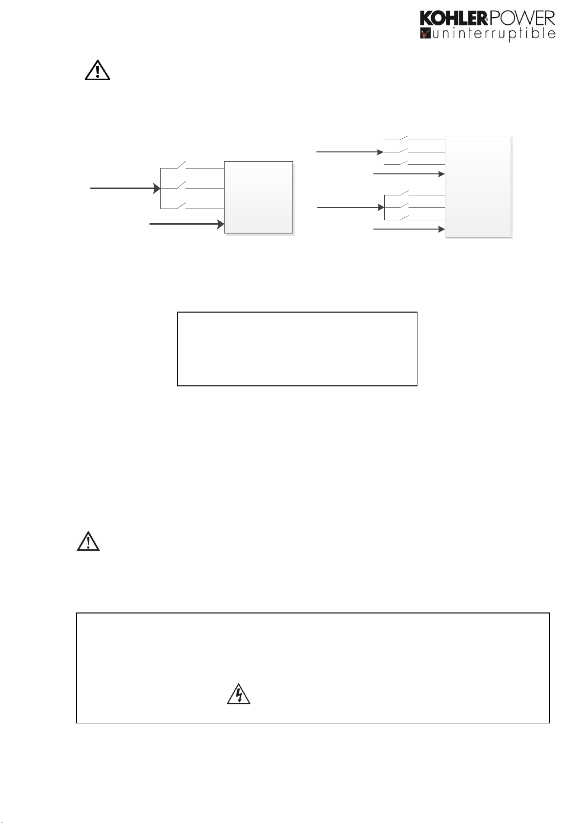
1-4. CONNECTION WARNINGS ..............................................................................................................2
1-5. OPERATION ........................................................................................................................................3
1-6. STANDARDS ........................................................................................................................................3
2. INSTALLATION AND OPERATION ................................................................................................. 4
2-1. UNPACKING AND INSPECTION ..................................................................................................................4
2-1-2 POSITIONING ....................................................................................................................................4
2-2. REAR SYSTEM VIEW..............................................................................................................................5
2-3. SINGLE UPS INSTALLATION ....................................................................................................................7
2-4. UPS INSTALLATION FOR PARALLEL SYSTEM .................................................................................................9
3. OPERATIONS ............................................................................................................................... 10
3-1. INITIAL OPERATION ............................................................................................................................10
3-2. SCREEN DESCRIPTION .........................................................................................................................10
3-3. AUDIBLE ALARM.................................................................................................................................26
3-4. SINGLE UPS OPERATION......................................................................................................................27
3-5. PARALLEL OPERATION .........................................................................................................................29
3-6. FAULT CODE .....................................................................................................................................30
3-7. WARNING CODE ................................................................................................................................31
4. TROUBLE SHOOTING................................................................................................................... 32
5. STORAGE AND MAINTENANCE.................................................................................................... 33
5-1. STORAGE .........................................................................................................................................33
5-2. MAINTENANCE...................................................................................................................................33
6. SPECIFICATIONS ........................................................................................................................ 34
7. OPTIONS ..................................................................................................................................... 35
7-1 SNMP CARD -OPTIONAL ......................................................................................................................35
7-2 NETFEELER ENVIRONMENT MONITORING CARD.......................................................................................36
7-3 DRY PORT RELAY CARD -OPTIONAL .......................................................................................................37

1
1. Safety and EMC instructions
All safety instructions in this document must be read, understood and followed.
1-1. Transportation and Storage
Please transport the UPS system only in the original packaging to protect against shock and
damage.
The UPS must be stored in a room where the temperature is well regulated. Ambient
temperature should not exceed 40°C.
1-2. Preparation
Condensation may form if the UPS system is moved instantly from a cold to warm environment.
The UPS system must be dry before being installed. Please allow at least two hours for the UPS
system to acclimatise to the environment.
Do not install the UPS system near water or in humid environments.
Do not install the UPS system where it would be exposed to direct sunlight or nearby heat
source.
Do not block ventilation holes on the UPS housing.
1-3. Installation
Do not connect appliances or devices which would overload the UPS (e.g. big motor-type
equipment) to the UPS output terminal.
Place cables in such a way that no one can step on or trip over them.
Do not block air vents on the housing of the UPS. Ensure proper unit spacing of ventilation.
UPS chassis must both be connected to Site Potential Earth Terminals. Battery chassis must
have a Potential Earth connection directly to UPS, or the battery chassis must be connected to
site Potential Earth terminals directly.
The UPS must be installed only by a qualified engineer.
An appropriate disconnect device such as short-circuit backup protection should be incorporated
during installation.
An integral emergency shutoff switch which prevents additional load from the UPS in any mode
of operation should be implemented during the installation.
Secure the grounding/earthing wire to the terminal before connecting any live cable.
Installation and Wiring must be in accordance with the local electrical laws and regulations.

2
1-4. Connection Warnings
•There is no standard backfeed protection inside of the UPS. However, there are relays on the Input to
cut off line voltage and while the neutral is still connected to UPS.
Main
Input
Input Rly
UPS
L1
L2
L3
N
Main
Input
Input Rly
UPS
L1
L2
L3
N
Bypass
Input
Input Rly
L1
L2
L3
N
Input relay diagram Input relay diagram for dual-input model
•This UPS should be connected with TN grounding/earthing system.
◼The power input for this unit must be three-phase rated in accordance with the equipment
nameplate. It also must be suitably grounded.
•Use of this equipment in medical instrument or any life-sustaining equipment where failure of this
equipment can reasonably be expected to cause the failure of the life-sustaining equipment or to
significantly affect its safety or effectiveness is not recommended. Do not use this equipment in the
presence of a flammable mixture with air, oxygen or nitrous oxide.
•Connect grounding terminal of UPS to a grounding electrode conductor.
•In accordance with safety standard EN-IEC 62040-1, installation has to be provided with a《Backfeed
Protection》system, as for example a contactor, which will prevent the appearance of voltage or
dangerous energy in the input mains during a mains fault. (Respect the wiring diagram of «Backfeed
Protection» depending if the equipment is with signal or three phase input).
There shouldn’t be a spur circuit from the «Backfeed Protection» to the UPS, as the standard
safety would be infringed.
•Warning labels should be placed on all primary power switches installed in places away from the unit to
alert the electrical maintenance personnel of the presence of a UPS in the circuit. The label will bear the
following or an equivalent text:
Before working on this circuit
-Isolate Uninterruptible Power Supply (UPS)
-Then check for Hazardous Voltage between all terminals including the protected earth
Risk of Voltage Backfeed
WARNING
HIGH LEAKAGE CURRENT
EARTH CONNECTION ESSENTIAL
BEFORE CONNECTING SUPPLY

3
1-5. Operation
Do not disconnect the grounding/earthing conductor cable on the UPS or to the building wiring
terminals under any circumstance.
The UPS system features its own, internal current source (batteries). The UPS output sockets or
output terminal blocks may be electrically live even if the UPS system is not connected to the
building mains/live wires. (only for standard models)
In order to fully disconnect the UPS system, first press the “OFF” button and then disconnect
the mains/live cables.
Ensure that no liquid or other foreign objects can enter into the UPS system.
The UPS can be operated by any individuals with no previous experience.
1-6. Standards
* Safety
IEC/EN 62040-1
* EMI
Conducted Emission...............................:IEC/EN 62040-2
Category C3
Radiated Emission..................................:IEC/EN 62040-2
Category C3
*EMS
ESD........................................................:IEC/EN 61000-4-2
Level 4
RS..........................................................:IEC/EN 61000-4-3
Level 3
EFT.........................................................:IEC/EN 61000-4-4
Level 4
SURGE...................................................:IEC/EN 61000-4-5
Level 4
CS..........................................................:IEC/EN 61000-4-6
Level 3
Power-frequency Magnetic field................:IEC/EN 61000-4-8
Level 4
Low Frequency Signals............................:IEC/EN 61000-2-2
Warning: This is a product for commercial and industrial application in the
second environment-installation restrictions or additional measures may be
needed to prevent disturbances.

4
2. Installation and Operation
2-1. Unpacking and Inspection
Unpack the package and check the package contents. The shipping package should contain:
● One UPS
●One user manual
● One monitoring software CD
●One RS-232 cable (option)
●One USB cable
●One parallel cable (only available for parallel model)
●One shared current cable (only available for parallel model)
●1 x 2Way / 1 x 3Way / 1 x 4Way DIN Terminal Jumper Bars
NOTE: Before the installation, please inspect the unit. Be sure that there is no physical damage to the unit.
Do not turn on the unit and notify the carrier and dealer immediately if there is any damage or missing parts
and accessories. Please keep the original packaging for future use. It is recommended to keep each
equipment and battery set in their original packaging because they have been designed to provide
maximum protection during transportation and storage.
2-1-2 Positioning
The UPS system is on wheels and can be maneuvered on solid floor.
The “Positioning Diagram”below details the recommended clearance space around the UPS for correct air
flow.
Terminals are located on rear of UPS and access should be provided during installation and maintenance.
NOTE: For Maintenance purposes 600mm side clearance is required to access batteries and components on
both sides. If 600mm side clearance is not available, extra cable should be fitted to allow the UPS to be
withdrawn from its position to allow access.
Positioning Diagram

5
2-2. Rear System View
Diagram 1 Rear Panel Diagram 2: Input/Output terminals
1. RS-232 port
11. Line input terminals
2. USB communication port
12. Output terminal
3. Emergency power off connector (EPO
connector)
13. Input ground terminal
4. Parallel Share current port
14. Output ground terminal
5. Parallel port
15. Bypass input circuit breaker/switch
6. Intelligent slot –SNMP or DRY Port
16. Bypass input terminals
7. External battery connector/terminal
17. Output switch
8. Line input circuit breaker/switch
18. Service start
9. Maintenance bypass switch
19. External Maintenance Bypass Switch connector
(EMBS)
10. Input/Output terminals (Refer to diagram 2
for the details)

6
1. RS232 Port –Port is used by Maintenance Service engineer to enable updates to internal firmware
of the UPS System. Not for Customer Use
2. USB Port –Communication port for Customer to connect monitoring Software directly to local PC,
provides Alarms and functional monitoring.
3. EPO –EPO port is NC in normal Operation. Breaking this NC loop forces the UPS Inverter to
disconnect the output to the load.
4. Parallel Share Current Port –Used when multiple UPS systems are connected in Parallel
5. Parallel Port –Used when multiple UPS systems are connected in Parallel
6. INTELLIGENT SLOT –One Slot provided can hold either an SNMP card or Dry port card.
a. SNMP CARD –OPTIONAL (Further details in Section 7.1)
b. DRY PORT RELAY CARD –OPTIONAL (Further details in Section 7.3)
18. SERVICE START –Allows UPS to be started directly from the battery with no incoming mains
supplied.
19. EMBS (External Maintenance Bypass Switch) –Port is NC in Normal Operation.
The EMBS port can be linked to an external Maintenance bypass switch to ensure an interlock is
connected to the UPS internal static switch. When installed and the EMBS is closed the Inverter is
shutdown and the static transfer switch connects the load directly to the incoming mains supply.

7
2-3. Single UPS Installation
Installation and wiring must be carried out in accordance with the local installation regulations by trained
professionals.
1) Make sure that the mains cable and breakers of the building are rated for the capacity of the UPS to
prevent electric shock or risk of fire.
NOTE: Do not use a standard wall mains socket as the input power source for the UPS, as its rated current
is less than the UPS’s maximum input current. The socket may be damaged and destroyed.
2) Switch off the mains switch in the building before installation.
3) Turn off all the connected devices before connecting to the UPS.
4) Prepare cables based on the following table:
Model
Wiring spec (mm² & Max A Per Phase)
Bypass
Input
(if used)
Input
(1Ph)
Input
(3Ph)
SINGLE
Input
(3Ph)
DUAL
Output
(Ph)
Neutral
Battery
Ground
PW3000/P1 10K
10mm
(67A)
10mm
(67A)
10mm
(67A)
4mm
(23A)
10mm
(45A)
10mm
10mm
(60A)
10mm
PW3000/P1 20K
25mm
(132A)
25mm
(132A)
25mm
(132A)
10mm
(45A)
25mm
(86A)
25mm
25mm
(110A)
25mm
NOTE 1: The selection for cable sizing should be based on the cable specification used and the type
of cable installation. Local electrical laws and regulations should be followed.
NOTE 2: The selections for color of cables should be followed by the local electrical laws and
regulations.
NOTE 3: Maximum current is based on Input Voltage of 209V, 130% load with 12A Charger fully
operating.
5) Remove the terminal block cover at the rear panel of UPS. Then connect the wires according to the
following terminal block diagrams: (Connect the grounding/earthing wire first when making wire
connections. Disconnect the earth wire after you disconnect the power wire.)
Terminal block wiring diagram

8
NOTE 1: Make sure that the wires are connected tightly with the terminals.
6) Put the terminal block cover back at the rear panel of the UPS.
The PowerWAVE 3000/P1 System Can be modified to operate at various configurations of inputs. To
change the configuration, insert or remove the provided jumper bars on the terminal rail as detailed below:
Warning:
● Make sure a DC breaker or other protective device between UPS and the external battery pack is
installed. Switch off the battery breaker before installation.
NOTE: Set the battery pack breaker in “OFF” position and then install the battery pack.
● Pay attention to the rated battery voltage marked on the rear panel. If you want to change the numbers
of the battery pack, please make sure you modify the setting simultaneously. The Connection with
wrong battery voltage may cause permanent damage to the UPS. Make sure the voltage of the battery
pack is correct.
● Pay attention to the polarity marking on external battery terminal block and make sure the correct
battery polarity is connected. Wrong connection may cause permanent damage to the UPS.
●Make sure the protective earth ground wiring is correct. The wire current spec, color, position,
connection and conductance reliability should be checked carefully.
● Make sure the utility input & output cable is sized correctly. The cable current spec, color, position,
connection and conductance reliability should be checked carefully. Make sure the L/N side is correct,
not reverse or short-circuited.

9
2-4. UPS Installation for Parallel System
If the UPS is being installed for single operation, you may skip this section.
1) Connect the Parallel (dash lines) & Current Share cables as per the following drawings:
2 X SYSTEM IN PARALLEL 3 X SYSTEMS IN PARALLEL
2) Install and cable the UPS according to the section 2-3.
3) Connect the output cables of each UPS to a separate output breaker.
4) Connect the input cables of each UPS to a separate input breaker.
5) Connect all output breakers to a main output breaker. Then this main output breaker will directly
connect to the loads.
6) Common battery packs or independent battery packs can be installed.
7) Refer to the following wiring diagram:

10
Wiring diagram of parallel system
3. Operations
3-1. Initial Operation
1) Before operation, make sure that the two string halves of batteries are connected correctly in order
of ”+,GND,-”terminals and the breaker of the battery pack is at “ON” position.
2) Start up UPS system by closing the Input and Bypass breakers, check all settings and configurations
before starting up the UPS fully in section 3-4.
3-2. Screen description
After initialisation, the LCD will display main screen. There are five sub-menus: Control, measure, setting,
information and data log. Touch any sub-menu icon to enter into the sub-screen.

11
Menu tree

12
3-2-1 Main screen
Upon powering on, the LCD will start initialisation after a few seconds as shown below.
After initialisation, the main screen will display as shown below. On the bottom, there are five icons to
represent five sub-menus: CONTROL, MEASURE, SETTING, INFO, DATALOG.
3-2-2 Control screen
Touch the icon to enter control sub-menu.
Touch icon to return back to main screen regardless of the screen of any submenu.

13
HOME CONTROL
ON/OFF UPS
MUTE ALL
ConfirmYES Turn ON /OFF UPS
ConfirmYES Do Battery Test
Confirm YES Do MUTE ALL
Enter No Or Back
Enter No Or Back
Enter No Or Back
ON/OFF CHARGER
BATTERY TEST
ConfirmYES Turn ON/OFF CHARGER
Enter No Or Back
Screen 1.0 «Control» and its sub-menus
➢On/Off UPS
It will show “Turn on UPS?” when UPS is off.
It will show “Turn off UPS?” when UPS is on.
Touch “YES” to turn on or off the UPS. Then, the screen will return to main screen
Touch “Back” to return to main screen immediately or “No” to cancel this operation and back to main
screen.
TURN ON UPS TURN OFF UPS
➢Battery Test
It will show “Battery Test” if the UPS is not in test. Touch “Yes” to start battery test. Then, it will show
“Battery testing...…” during battery test period. After a few seconds, battery test result will show on
the screen. Touch “Back” to return to main screen immediately or “No” to cancel this operation and
back to main screen.
It will show “Cancel battery test” if the UPS is in test.

14
Battery Test Cancel Battery Test
➢Audio mute
It will show “Mute all” if the audio is active. Touch “Yes” to activate mute. If “Mute all” is active, it will
show icon on the top left corner of the main screen. Touch “Back” to return to CONTROL screen
immediately or “No” to cancel this operation and back to CONTROL screen.
It will show “Cancel mute” if the UPS is mute already. Touch “Yes” activate audio function or “No” to
keep mute. Touch “Back” to return to CONTRL screen.
Mute All Cancel Mute all
➢On/Off Charger
It will show “Turn on Charger?” when charger is off.
It will show “Turn off Charger?” when charger is on.
Touch “YES” to turn on or off the charger. Then, the screen will return to main screen.
Touch “Back” to return to CONTROL screen immediately or “No” to cancel this operation and back to
CONTROL screen.
TURN ON CHARGER TURN OFF CHARGER
➢EXIT PARALLEL
In the case of multiple machines in parallel, clicking this option will pop up the “Exit Parallel?”
interface;
Click "Yes" to exit the machine from the current parallel system;
Click "No" to cancel this operation and return to the operation interface.
In the case of a single machine, clicking this option will pop up the "This mode can’t be SETUP!".

15
EXIT PARALLEL? This mode can’t be SETUP!!
3-2-3. Measure screen
Touch the icon to enter measure page. Touch the icon or to browse information.
Touch the icon to return to main screen. Touch the icon to go back to previous menu.
Measure screen page 1
➢LINE VOL: The real time value of L1, L2 and L3 phase voltage, L1-L2, L2-L3, L3-L1 voltage and input
frequency.
➢INVERTER VOL: The real time value of L1 inverter voltage and frequency.
➢BYPASS VOL: The real time value of L1 bypass voltage and frequency.
➢OUTPUT VOL: The real time value of L1 output voltage and frequency.

16
Measure screen page 2
➢OUTPUT W: L1 output power in watt.
➢OUTPUT VA: L1 output power in VA.
➢OUTPUT W (%): L1 output power watt in percentage.
➢OUTPUT VA (%): L1 output power VA in percentage.
➢Total watt and VA: Total output load in watt and VA.
➢Backup Time: Display battery backup time (Min & sec).
➢BATT Voltage/Bus Voltage/Charging Current/Discharging Current: The real time value of DC related
information.
➢Temperature: Temperature of L1 = PFC Main Board, L2 = Inverter Main Board and L3 = bypass temp.
Measure screen page 3
➢INPUT W: L1, L2 and L3 input power in watt.
➢INPUT VA: L1, L2 and L3 input power in VA.
➢INPUT W (%): L1, L2 and L3 input power watt in percentage.
➢INPUT VA (%): L1, L2 and L3 input power VA in percentage.
➢Input current: The real-time value of input current in L1, L2 and L3 phases.
➢Output current: The real-time value of output current in L1 phases.

17
3-2-4. Setting screen
This sub-menu is used to set the parameters of UPS. Touch the icon to enter setting menu page.
There are 2 options: General and Advanced. Touch the icon to return to main screen. Touch the
icon to go back to previous menu.
NOTE: Not all settings are available in every operation mode. If the setting is not available in present mode,
the LCD will keep its original setting parameter showed instead of changing the parameters.
Setting screen
➢GENERAL: Basic information of the UPS. Only function parameter’s can be accessed.
➢ADVANCE: Enter password to access to the “ADVANCE” setting. There are two types of authority, User
and Maintainer.
GENERAL
General screen page 1
➢Language: Set the LCD language.
➢Input Source: Select the input source. There are two options: Line (utility) and generator. Line is
default setting. This setting value will show on the main page. When “generator” is selected, the
acceptable input frequency will be fixed at the range of 40~70Hz. This setting value will show on the
status bar.
This manual suits for next models
2
Table of contents
Other Kohler UPS manuals

Kohler
Kohler PowerWave 9000DPA S2 User manual

Kohler
Kohler PW 6000 User manual

Kohler
Kohler PW 1000/LT Series User manual

Kohler
Kohler PW 9000DPA User manual

Kohler
Kohler PW 5000/TP User manual

Kohler
Kohler PowerWAVE 9500DPA User manual

Kohler
Kohler PowerWAVE 8000DPA RI (S2) Series User manual

Kohler
Kohler PW 6000 User manual

Kohler
Kohler PowerWAVE 6000 User manual

Kohler
Kohler PW1000 2 kVA User manual