Kohler PW1000 2 kVA User manual

PowerWAVE 1000
(1–3 kVA)
User Manual

TS_600_00 PW1000 1-3kVA User Manual 6/4/17

TS_600_00 PW1000 1-3kVA User Manual 6/4/17
Document Control
PDF ISSUE DATE REVISION SUMMARY
TS_600_00 06/04/2017 First Issue

TS_600_00 PW1000 1-3kVA User Manual 6/4/17
Uninterruptible Power Supplies Ltd has taken every precaution to
produce an accurate, complete and easy to understand manual and will
therefore assume no responsibility nor liability for direct, indirect or
accidental personal or material damage due to any misinterpretation of or
accidental mistakes in this manual.
© 2017 Uninterruptible Power Supplies Ltd
This manual may not be copied or reproduced without written permission
of Uninterruptible Power Supplies Ltd.
USEFUL CONTACTS
www.upspower.co.uk UPS Limited web site
[email protected] Technical queries
[email protected] Hardware sales
[email protected] Extended warranty agreements etc

TS_600_00 PW1000 1-3kVA User Manual 6/4/17 I
Table of Contents
Safety 1
1.1 Description of symbols used in this manual 1
1.2 User precautions 1
1.3 Important safety notes 2
1.4 Storage instructions 2
General Description 3
2.1 Introduction 3
2.1.1 Advanced design features 3
2.1.2 PW1000 1-3kVA Model range 4
2.2 UPS Operating principles 4
2.2.1 Basic block diagram 4
2.2.2 System operating modes 5
2.3 Operator control panel 7
2.3.1 LED Indicators 7
2.3.2 Operator keypad 8
2.3.3 LCD Display 8
2.4 UPS Rear view 10
2.4.1 Communication Ports 10
2.5 External battery cabinet 12
2.6 Warranty 13
2.6.1 Extended warranty 13
2.6.2 Additional service/maintenance support 13
Installation 14
3.1 Unpacking the UPS equipment 14
3.2 Selecting a suitable installation location 14
3.2.1 Clearances 15
3.3 Assembling the UPS mounting hardware 17
3.3.1 Hardware accessories pack 17
3.3.2 Stand-alone Tower assembly 17
3.3.3 Rack installation 17
3.4 Assembling the external battery cabinet mounting hardware 20
3.4.1 Stand-alone tower installation 20
3.4.2 Combined tower installation 21
3.4.3 Rack installation 21
3.5 Electrical installation 22
3.6 Initial UPS power-up and commissioning 22
Operation 23
4.1 Introduction 23
4.2 UPS start-up procedures 24
4.2.1 How to start the UPS (from utility mains) 24
4.2.2 How to start the UPS (from battery) 25

:
II TS_600_00 PW1000 1-3kVA User Manual 6/4/17
4.2.3 How the monitor the UPS input/output operating conditions 26
4.3 UPS shut down procedures 27
4.3.1 How to turn off the UPS (from ON INVERTER or ECO Mode) 27
4.3.2 How to turn off the UPS (from ON BATTERY Mode) 27
4.4 Manual load transfer between inverter and bypass 27
4.5 Functions menu 28
4.5.1 How to disable the alarm buzzer operation 28
4.5.2 How to perform a battery test 28
4.5.3 Functions menu 29
4.5.4 Operating parameters setting menu 30
Maintenance 31
5.1 Introduction 31
5.2 Scheduled maintenance 31
5.2.1 Preventative maintenance inspection 31
5.2.2 Battery maintenance and testing 31
Troubleshooting 33
6.1 Introduction 33
6.2 Fault identification 33
6.2.1 Error codes 33
6.2.2 Audible warning alarm 33
6.2.3 Warning symbols 34
6.3 Troubleshooting a fault condition 34
6.4 Troubleshooting an operational problem 35
6.5 UPS Fault handling 35
6.5.1 Output load short circuit when the output supply is via inverter 36
6.5.2 Output short-circuit when the output supply via the bypass line 36
6.5.3 Inverter/internal over-temperature 36
6.5.4 Inverter over-current and output voltage out of tolerance 36
6.6 UPS System reset 36
Options 37
7.1 Communications options 37
7.2 RS-232 Computer serial interface 37
7.3 Emergency Power Off (EPO) / Remote ON/OFF (ROO) 38
7.4 CS141 /SMNP adapters 38
7.5 AS400 (dry contact) card 39
Specification 40

TS_600_00 PW1000 1-3kVA User Manual 6/4/17 1
1Safety
1.1 Description of symbols used in this manual
1.2 User precautions
WARNING: The warning symbol is used where there is danger of an electrical shock, equipment damage or
personal injury.
CAUTION: The caution symbol is used to highlight important information to avoid possible equipment
malfunction or damage.
WARNING: Do not attempt to install this UPS system until you are satisfied that you have read and understood
ALL the safety instructions and hazard warnings contained in this manual.
WARNING: Keep this manual with the UPS for future reference.
WARNING: DO NOT OPEN THE CASE. If you open the case of the UPS you will be exposed to dangerous
voltages. The UPS does not contain any user-serviceable parts, so do not attempt to repair this unit yourself as
doing so will void your warranty. If the UPS malfunctions it must be serviced or repaired by a trained engineer.
Always contact your local service agent if repair is necessary.
WARNING: Do not disconnect the power cord from the UPS AC Input socket while the UPS is turned on. The
UPS is equipped with an EMI filter, and to prevent a potential leakage current hazard the AC mains supply must
be securely grounded at all times. You should double check that the UPS supply earth connection is properly
grounded before you connect AC mains to the UPS.
WARNING: Uninterruptible Power Supplies Ltd will assume no responsibility or liability for accidents or injuries
due to incorrect operation or manipulation of the UPS or peripheral equipment.
CAUTION: The PW1000 1-3kVA is a Class A UPS product (according to EN 62040-3).
In a domestic environment the UPS may cause radio interference and the user may be required to undertake
additional measures.

1: Safety
2TS_600_00 PW1000 1-3kVA User Manual 6/4/17
1.3 Important safety notes
1. The UPS warranty will become null and void if liquids are spilt on the UPS case, or foreign objects are dropped into
the unit. Such mishaps could severely damage the UPS and present a shock hazard to anyone who touches the unit.
2. The ventilation grills on the UPS front panel must be kept free of obstruction at all times.
3. The UPS is must be installed in a sheltered and controlled environment away from direct sunlight. The operating
temperature should be between 0~40°C (ideally 20°C) with relative humidity of 0~90%, non-condensing. Further
details concerning the installation environment are included in the installation chapter of this manual.
4. Before installing the equipment you must check to ensure that the input voltage stated on the UPS data-plate on the
back of the unit matches your local utility supply voltage.
5. The UPS warranty will be rendered void, and the manufacturer reserves the right to refuse replacement or
compensation, if the UPS malfunctions due to:
• Accidental damage to the UPS.
• Damage or malfunction due to installing the UPS in an environment that does not meet the conditions specified in
this manual.
• Damage or malfunction due to improper installation, configuration or maintenance carried out by an unauthorised
person.
1.4 Storage instructions
If you intend to store the UPS for an extended period, in a moderate climate, the batteries should be charged for 12 hours
every 3 months by connecting the UPS to the utility supply. If the ambient temperature at the storage location is above
25°C, this should be carried out every 2 months.
CAUTION: Please read the following notes carefully prior to installation and use.
CAUTION: Always switch off the UPS before moving it.

TS_600_00 PW1000 1-3kVA User Manual 6/4/17 3
2General Description
2.1 Introduction
Congratulations on your purchase of the PW1000 1-3kVA UPS.
High reliability, low operating cost and excellent electrical performance are just some of the highlights of this innovative
UPS solution.
Uninterruptible Power Supplies Ltd. specialises in the installation and maintenance of Uninterruptible Power Systems; and
this UPS is just one example of our wide range of state-of-the-art power protection devices that will provide your critical
equipment with a steady and reliable power supply for many years.
2.1.1 Advanced design features
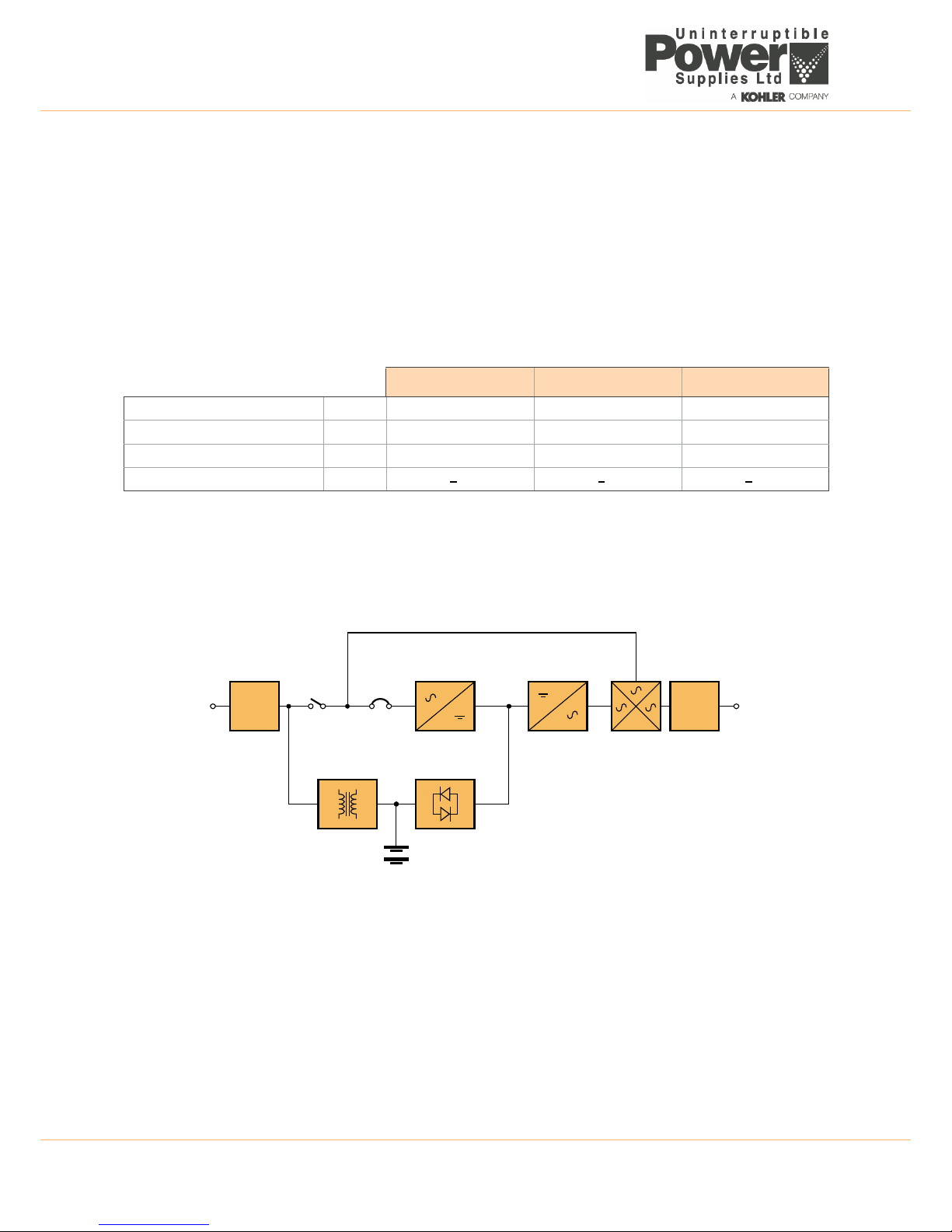
By using the latest technological developments in power engineering, the PW1000 1-3kVA represents a new generation of
transformerless UPS-System. Its advanced double conversion Voltage and Frequency Independent (VFI) topology
responds fully to both the highest availability and environmentally friendly requirements, compliant with IEC 62040-3 (VFI-
SS-111) standards. A full UPS specification is provided in Chapter 8 of this manual.
Following, are some of this unit’s advanced design features:
• True online technology continuously supplies your critical applications with stable, regulated, transient-free pure
sine-wave AC power.
• High-Frequency Transformerless technology and tower-convertible enclosure enables the UPS to be integrated
into even the most difficult environments with space constraints.
• User-friendly design that permits simple and trouble-free installation. All units are supplied with input and output
power cables as standard.
• Smart battery management system which extends the battery life span.
• Highly efficient PWM sine-wave technology yields excellent UPS efficiency. The high crest factor of the inverter
handles peak inrush current loads and so avoids a need to upgrade to a UPS with a higher power rating.
• Compliant with various stringent international EMC standards for electromagnetic interference & protection.
• Selection of output voltages (200/208/220/230/240) available to match the UPS to local supply specifications or
specific load voltage requirements.
• A selectable bypass voltage tolerance (low/high sensitivity) restricts the range of voltages that can be applied to the
load when the UPS operates on bypass. The ranges are ±15% (low sensitivity) and ±10%V (high sensitivity). For
example, if the output voltage setting is 230V the bypass sensitivity Low range is 230V ±15%.
• Selectable 50Hz or 60 Hz operation.
• Fully digitized control logic for better functionality and enhanced power protection. Digital signal processing (DSP)
also provides efficient communication capabilities for enhanced remote control and monitoring flexibility.
• Active power factor correction (PFC) control function constantly maintains the UPS input power factor to >0.99 at
100% load, with resulting outstanding energy efficiency.
• Wide input voltage tolerance, from 110V~300V, allows the UPS to operate normally without draining the battery
unnecessarily during significant mains voltage dips, which helps extend the battery service life.
• DC-start function permits the UPS to be started during a utility power failure if required.
• Overload protection system automatically switches the UPS to bypass mode if an overload occurs and
automatically switch back to inverter mode once the overload condition ceases. Should the output become short-
circuited, the UPS puts the system in stand-by mode, provides visible and audible alarms, and turns off the output
supply automatically until the short circuit situation is resolved manually.

2: General Description
4TS_600_00 PW1000 1-3kVA User Manual 6/4/17
2.1.2 PW1000 1-3kVA Model range
The PW1000 1-3kVA UPS range comprises 1 kVA, 2 kVA and 3 kVA models, each of which is designed as a self-
contained UPS comprising a rectifier, battery charger, inverter, static switch and battery pack. All the models in this range
are easy to install, and supplied with suitably terminated power cables.
The PW1000 1-3kVA operates as a stand-alone UPS module and can be mechanically configured as a floor-standing
tower unit or installed in a standard 19 inch rack. An accessory pack which contains all the parts necessary to configure
the unit for either type of installation is supplied with the UPS.
Optional external battery cabinets are available to increase the UPS autonomy time. The battery cabinet design
compliments the UPS cabinet and the two cabinets can be mechanically connected together to form a single unit when
installed as a tower system – see chapter 3 (Installation) for mechanical configuration details.
2.2 UPS Operating principles
2.2.1 Basic block diagram
Figure 2.1 UPS Functional block diagram
EMI Filters
The UPS has an input and output EMI filter to reduce the effects of electromagnetic noise generated by the UPS on other
adjacent equipment – e.g. reduces external radio interference.
Battery charger
A regulated battery charger, power from the AC Input supply, charges the battery whenever the input supply is available.
DC/DC Boost converter
In times of AC Input supply failure, the DC/DC Boost Converter turns on and boosts the battery voltage to a level suitable
for use by the inverter. It provides a regulated DC output for the inverter while the battery voltage decays during discharge
and includes voltage and current monitoring and overload protection.
1 kVA 2 kVA 3 kVA
Maximum output power (0.9 pf) kVA (kW) 1.0 (0.9) 2.0 (1.68) 3.0 (2.7)
Dimensions (WxHxD) mm 440 x 88 x 400 440 x 88 x 600 440 x 88 x 600
Weight (with internal batteries) kg 12 22 26.5
Sound level dBA <50 <50 <50
EMI
FILTER
EMI
FILTER
AC/DC (PFC)
CONVERTER
DC/AC
INVERTER
STATIC
SWITCH
BATTERY
CHARGER
DC/DC BOOST
CONVERTER
BATTERY
AC
Input
AC
Output
Bypass Line
Safety
Relay
Input
CB

TS_600_00 PW1000 1-3kVA User Manual 6/4/17 5
2: General Description
AC/DC Converter
As its name suggests, the AC/DC Converter converts the AC Input supply into a controlled DC supply that is suitable for
use by the inverter. The converter uses a leading-edge switched-mode technique which produces an input power factor of
almost unity over its full operating range (0.99 at full rated linear load) and thereby maximises the UPS efficiency.
The converter can satisfy the inverter DC power demands over an AC Input voltage range of between 110V~300V which
means that the battery is not called upon during power dips (brownouts), thereby maximising battery life and availability.
DC/AC Inverter
The inverter converts the DC voltage connected to its input, from the AC Input supply via the AC/DC converter or from the
battery via the DC/DC converter, and produces a regulated AC Output voltage that is suitable to power the connected load
equipment. The control logic associated with the Inverter power block is substantial, and in addition to the controlling the
output sine wave voltage it also provides various levels of overload protection, frequency regulation and synchronisation,
and output voltage error detection.
Static switch
The static switch provides a means of connecting the UPS AC Output (load) to the inverter output or the bypass line,
which is connected directly to the UPS AC Input. The control logic within this power block will transfer the load to the
bypass supply in the event of overload or UPS (inverter) malfunction. The load can also be transferred between the
inverter and bypass line manually if required. Note that a controlled transfer can take place only if the inverter and bypass
line are synchronised in frequency and phase.
2.2.2 System operating modes
ON-INVERTER operation
Figure 2.2 ON-INVERTER operation
• The battery is being permanently charged by the battery charger.
• The AC/DC converter is processing the AC Input supply and turning it into controlled DC.
• The inverter is converting the AC/DC converter output back into AC suitable for the load.
• The static switch is connecting the inverter output to the UPS AC Output terminals.
EMI
FILTER
EMI
FILTER
AC/DC (PFC)
CONVERTER
DC/AC
INVERTER
STATIC
SWITCH
BATTERY
CHARGER
DC/DC BOOST
CONVERTER
BATTERY
AC
Input
AC
Output
Bypass Line
Safety
Relay
Input
CB

2: General Description
6TS_600_00 PW1000 1-3kVA User Manual 6/4/17
ON BATTERY operation
Figure 2.3 ON-BATTERY operation
• The battery is discharging through the DC/DC boost converter which presents the inverter with a controlled input
voltage as the battery discharges.
• The Inverter is converting the DC/DC boost converter output back into AC suitable for the load.
• The static switch is connecting the inverter output to the UPS output terminals.
• The load will continue to receive its regulated power until the battery discharges to its low voltage cut-out level.
ON BYPASS operation
Figure 2.4 ON-BYPASS operation
• The battery is being permanently charged by the battery charger as long as the battery charger is still serviceable
and able to operate. If the load has transferred to bypass due to an internal malfunction the battery charger may
have shut down.
• The AC/DC converter, DC/DC boost converter and inverter are all inoperative.
• The static switch is connecting the bypass line to the UPS output terminals.
Note: When operating in this mode the load is unprotected from utility power disturbances.
EMI
FILTER
EMI
FILTER
AC/DC (PFC)
CONVERTER
DC/AC
INVERTER
STATIC
SWITCH
BATTERY
CHARGER
DC/DC BOOST
CONVERTER
BATTERY
AC
Input
AC
Output
Bypass Line
Safety
Relay
Input
CB
EMI
FILTER
EMI
FILTER
AC/DC (PFC)
CONVERTER
DC/AC
INVERTER
STATIC
SWITCH
BATTERY
CHARGER
DC/DC BOOST
CONVERTER
BATTERY
AC
Input
AC
Output
Bypass Line
Safety
Relay
Input
CB

TS_600_00 PW1000 1-3kVA User Manual 6/4/17 7
2: General Description
2.3 Operator control panel
The UPS is controlled from the operator control panel located on the front of the unit.
The user-friendly UPS control panel comprises three areas:
Figure 2.5 Operator control panel
2.3.1 LED Indicators
Input mains supply status
This led is permanently ON if the mains supply is within in the normal operating range of 160~300 VAC, and
flashes if the supply falls to 120~159 VAC. If the led is OFF it indicates a mains supply failure.
Programmable outlet status
The programmable outlets are normally connected to less critical loads which can be shed when the utility
power fails. This reduces the load on the battery as it discharges and thereby increases the back-up time for
the more critical loads which are connected to the unswitched UPS outlet(s). The indicators are permanently
ON when the outlets are live.
Bypass supply status
This led is permanently ON when the UPS is operating in the ECO mode and flashes when the load is
transferred to bypass – either manually or due to a detected fault.
UPS fault indication
This LED illuminates to indicate the presence of a fault condition within the UPS that needs attention. It is
usually accompanied by an audible alarm.
ON OFF Enter
Function
INPUT
UPS
LOAD
Service
Overload
Utility
?
Wiring Fault
Alarm
Bypass
Fault
Parallel ID Mode KVA
WHz
Mins
%
C
Bypass Step
Utility Inverter
VoltageAdjust
Buzzer Code
BatteryAutonomy
Frequency Window
Low
Testing
1
2
Led indicators
A row of LEDs indicate the UPS input and
output power status, together with a
general fault warning.
LCD Display
Provides indication of the UPS operating
mode together with the input, output, and
battery supply parameters. It also displays
error messages and UPS set-up data via a
system of configuration menus.
Operator Keypad
The keypad contains 6 keys that are used
to navigate through the UPS control menu
system and turn the UPS OFF/ON.
1

2: General Description
8TS_600_00 PW1000 1-3kVA User Manual 6/4/17
2.3.2 Operator keypad
2.3.3 LCD Display
The LCD display contains a row of warning symbols, a mimic diagram which indicates the power path through the UPS, a
battery status indicator and a multi-function 3-digit numerical display which can be selected to indicate a range of
operating parameters. Each of these areas are described below.
Figure 2.6 LCD Display
ON Button
This button is used to turn ON the UPS and activate certain functions when operated in combination
with other buttons (as described later in this chapter). The button must be pressed for approximately
one second to turn ON the UPS – accompanied by double ‘beep’.
This symbol shows that the ON button is also used to cancel the audible alarm. When the alarm is
cancelled, the audible warning will turn OFF but the alarm LED will remain ON if the fault is still present.
OFF Button
This button must be pressed for approximately one second to turn OFF the UPS – accompanied by
double ‘beep’.
ENTER Button
The ENTER button is used to select a parameter from the UPS monitoring and configuration menus.
UP (BACK) Button
This button is used to navigate UP through the UPS menus, or change a menu parameter. It is also
used with the ON button to manually transfer the load between the UPS and bypass supply.
DOWN (NEXT) Button
During normal operation, this button is used to scroll through the metered parameters shown on the
LCD display. It is also used in conjunction with the ON button to access the UPS configuration menus.
FUNCTION Button
This button is used to access the UPS configurations display menu.
ON
OFF
Enter
Function
INPUT
UPS
LOAD
Service
Overload
Utility
?
Wiring Fault
Alarm
Bypass
Fault
ParallelID Mode KVA
WHz
Mins
%
C
Bypass Step
Utility Inverter
VoltageAdjust
Buzzer Code
BatteryAutonomy
Frequency Window
Low
Testing
Warning symbols
Mimic diagram
Battery status
Metering parameters
3-Digit alpha-numeric display

TS_600_00 PW1000 1-3kVA User Manual 6/4/17 9
2: General Description
Warning symbols
Mimic diagram
The LCD Mimic diagram indicates the existing power flow through the UPS. The INPUT, UPS, LOAD and BATTERY
symbols are permanently shown on screen and their interconnecting lines appear, or disappear, depending on the UPS
mode of operation – see the table below.
Bypass input abnormal:
UPS fails to transfer to bypass, bypass abnormal in ECO mode
Utility input abnormal:
The utility mains supply is outside the UPS pre-set operating window
Wiring fault:
Site wiring problem such as reversed Line-Neutral connection
Alarm buzzer silent
The alarm buzzer has been silenced or disabled
Overload:
The UPS output is overloaded
Service:
The UPS is operating in its service mode
Alarm:
An alarm condition is present. This remains active after the audible alarm is reset if the alarm still exists.
UPS OFF
This mimic is displayed when the utility power is first applied to the UPS, or if the UPS is
turned OFF. It shows that the battery is being charged from the utility supply (INPUT) but
the LOAD is not connected to the UPS, and is therefore unpowered.
ON INVERTER
This mimic is displayed during normal UPS operation. It shows the battery being
charged from the utility supply (INPUT) and the LOAD connected to the UPS output
(Inverter), and is therefore being supplied with processed, backed-up power.
ON BATTERY
This mimic is displayed if the utility supply fails. It shows the battery now providing the
UPS (Inverter) and LOAD power. The battery will sustain the UPS output until it is fully
discharged, whereupon the UPS will shut down.
Bypass
Utility
?
Wiring Fault
Overload
Service
Alarm
INPUT
UPS
LOAD
INPUT
UPS
LOAD
INPUT
UPS
LOAD

2: General Description
10 TS_600_00 PW1000 1-3kVA User Manual 6/4/17
Battery status indicators
There are three ‘flags’ to the left of the battery icon which indicate the battery status.
Fault
Indicates a battery fault and is normally accompanied by an illuminated Alarm warning symbol
and an audible warning from the buzzer. An error code will be shown on the LCD 3-digit
alphanumeric display which helps with fault identification.
Low
When the UPS is operating ON BATTERY the Low flag will turn on when the battery is nearing its end of discharge. This is
accompanied by an increase in the number of short successive beeps produced by the alarm buzzer.
Testing
The Testing flag flashes when a battery test is operation – see paragraph 4.5.2.
Meter Display
When the UPS is turned ON, you can use the DOWN and UP buttons to scroll through the measurement display screens.
The display sequence is as numbered in the table below and loops around in either direction.
2.4 UPS Rear view
2.4.1 Communication Ports
Several communication options can connected to the PW1000 1-3kVA. These are described briefly below with further
details provided in Chapter 7 (Options).
USB port (Figure 2.7 item 3)
A USB type B socket is provided to allow the UPS to be connected to a PC using a standard USB peripheral interface
cable. The USB communication protocol complies with USB version 1.0 (1.5 Mbps) and USB HID version 1.0. This facility
can be used in conjunction with UPS monitoring and shut down software (not supplied).
RS-232 Interface port (Figure 2.7 item 2)
The RS-232 port allows the UPS to be connected to a PC and provides the same functions as the USB port.
Emergency power off (EPO) (Figure 2.7 item 1)
If an external emergency power off (EPO) facility is required, the external circuit must be connected to the two pin plug
located on the rear panel. A plug-in connector with screwed terminal connections is supplied ready fitted to the EPO
socket to simplify the connection of the external cable if the UPS is located in a confined space, such as when it is rack
mounted. The EPO input requires a normally-open contact which closes to active the EPO function. If the UPS is shut
down by the EPO input (closed), it has to be restarted manually after the EPO input is removed (opened).
Optional interface cards (Figure 2.7 item 4)
An optional SNMP/ CS141 interface card can be fitted in the card slot to enable the UPS to be integrated into a network
monitoring and control system.
ON BYPASS
This mimic is displayed if the UPS develops a fault, or is overloaded, whereupon the
LOAD is transferred to the bypass line and connected directly to the utility supply
(INPUT). The battery will remain on charge if the UPS battery charger is healthy.
1 Utility Voltage (V) 4 Inverter Frequency (Hz) 7 Battery Voltage (V)
2 Utility Frequency (Hz) 5 Inverter Load % 8 Battery Autonomy (mins)
3 Inverter voltage (V) 6 Inverter Load (A) 9 UPS Temperature (°C)
INPUT
UPS
LOAD
INPUT
UPS
LOAD
Fault
Low
Testing

TS_600_00 PW1000 1-3kVA User Manual 6/4/17 11
2: General Description
Figure 2.7 Rear panel detail
AC IN PUT
AC OUTPUT
INPUT BREAKER
EXT> BAT.
INTERFACE
12
EPO
RS232USB
AC OUTPUT
INPUT BREAKER
INTERFACE
AC INPUT
1
2
EPO
RS232USB
AC OUTPUT
INPUT BREAKER
BREAKER
OUTPUT
BREAKER
OUTPUT
INTERFACE
AC INPUT
AC OUTPUT
1
2
EPO
RS232USB
1
2
3
810 9
10
4 6 7
5
8
8
1 kVA
2 kVA
3 kVA
Model
Model
Model
1Emergency Power Off (by dry contact) 7Unswitched AC Outlets
2RS232 Port 8Two switched (programmable) AC outlets
3USB Port 9Mains input supply circuit breaker
4Communications card options slot 10 Cooling fans
5External battery connector 11/12 Output circuit breaker (CB) for AC Outlets 7/8
6AC Input (utility mains) power socket 13 16A Unswitched AC Outlet
7
9
56 4 7
1
2
3
114 896 7
510 7813 12
1
2
3

2: General Description
12 TS_600_00 PW1000 1-3kVA User Manual 6/4/17
2.5 External battery cabinet
An external battery pack can be connected to the UPS to extend the UPS autonomy time, where required. The batteries
are contained in a purpose-designed, matching cabinet which can be installed as a stand-alone unit or attached to the
UPS cabinet to form a single tower assembly.
When the external battery cabinet is rack-mounted it should be installed immediately below the UPS cabinet.
Note: If required, up to three external battery cabinets can be connected to the UPS – see Figure 2.8.
The following external battery cabinets are available:
Figure 2.8 External battery cabinet
Up to three external battery cabinets can be added to the UPS system by connecting the output cable of the first cabinet
(5) to the input connector of the second cabinet (4).
230V–1kVA 230V–2kVA 230V–3kVA
Battery voltage 36V 72V 72V
Battery number and capacity 6x 7Ah 12x 7Ah 12x 9Ah
Battery strings 2x Strings of 3 batts. 2x Strings of 6 batts. 2x Strings of 6 batts.
Dimensions (WxHxD) in/mm 17.3 x 3.5 x 15.8 in (2U)
440 x 88 x 400 mm
17.3 x 3.5 x 23.6 in (2U)
440 x 88 x 600 mm
17.3 x 3.5 x 23.6 in (2U)
440 x 88 x 600 mm
Weight kg/lb 11kg / 24.25lb 17.5kg / 38.6lb 17.5kg / 38.6lb
DC BREAKER
To Ext. Battery
UPS. B AT.
1 2 543
1DC Breaker (option) – Battery over-current protection
2DC Fuses – Battery over-current protection
3Earth – Safety earth bonding
4Input connector – For additional extended battery cabinets
5DC Power cord – Battery cable to UPS cabinet

TS_600_00 PW1000 1-3kVA User Manual 6/4/17 13
2: General Description
2.6 Warranty
The PW1000 1-3kVA UPS is supplied with a limited warranty that the UPS and its component parts are free from defects
in materials and workmanship for a period of one year from the date of commissioning or fifteen months from the date of
original delivery, whichever is the sooner. This warranty is the only warranty given and no other warranty, expressed or
implied, is provided.
This warranty does not apply to any losses or damages caused by misuse, abuse, negligence, neglect, unauthorised
repair or modification, incorrect installation, inappropriate installation environment, accident, act of God, or inappropriate
application. If the UPS fails to conform to the above within the warranty period then Uninterruptible Power Supplies Ltd.
will, at its sole option, repair or replace the UPS. All repaired or replaced parts will remain the property of Uninterruptible
Power Supplies Ltd.
As a general policy, Uninterruptible Power Supplies Ltd. does not recommend the use of its products in:
• life support applications where failure or malfunction of the product can be reasonably expected to cause failure of
the life support device, or to significantly affect it’s safety or effectiveness.
• applications concerned with direct patient care.
Uninterruptible Power Supplies Ltd. will not knowingly sell its products for use in such applications unless it receives in
writing assurances satisfactory to Uninterruptible Power Supplies Ltd. that:
• the risks of injury or damage have been minimized.
• the customer assumes all such risks.
• the liability of Uninterruptible Power Supplies Ltd. is adequately protected under the circumstances.
2.6.1 Extended warranty
The standard warranty may be enhanced by protecting the UPS with an extended warranty agreement (maintenance
contract).
An extended warranty agreement enhances the standard warranty by providing the following:
• regular preventative maintenance inspections.
• guaranteed speed of response to operational problems.
• 24 hour telephone support.
• fully comprehensive cover (excluding batteries and capacitors).
Contact the Service Support Hotline on 0800 731 3269 for further details.
2.6.2 Additional service/maintenance support
In addition to providing support for the PW1000 1-3kVA UPS, Uninterruptible Power Supplies Ltd. can provide
maintenance and support on a wide range of different UPS products. If you are interested in an extended warranty for your
PW1000 1-3kVA UPS, or for any other UPS products you may have, please contact us at the following address:
CAUTION: The UPS contains batteries that must be re-charged for a minimum of 12 hours every three months
to prevent deep-discharging. Batteries that have been deep-discharged, for whatever reason, are not covered
by this warranty.
Uninterruptible Power Supplies Ltd.
Woodgate
Bartley Wood Business Park
Hook
Hampshire
RG27 9XA
Tel: 01256 386700
0800 731 3269 (24 Hr.)
Fax: 01256 386701
Email: service@upspower.co.uk

14 TS_600_00 PW1000 1-3kVA User Manual 6/4/17
3Installation
3.1 Unpacking the UPS equipment
The manufacturer has designed robust packaging for your product to help ensure it reaches you in good order; however,
accidents and damage may sometimes occur during shipment. You should inspect the UPS carefully upon receipt and if
there are signs of damage you must inform the carrier and dealer immediately.
Save any recyclable packaging for re-use or dispose of it appropriately and correctly.
1. Remove the UPS from the packing carton.
2. Check the package contents. The standard unit includes:
a) User Manual.
b) IEC output cables (for UPS with IEC sockets only).
c) IEC input power cable (for UPS with IEC sockets only).
d) A UPS accessories kit which allows the UPS to be configured for Tower or Rack installation.
3. Before proceeding, check the data plate on the rear of the UPS and verify that the unit’s voltage and power ratings
comply with the equipment order details. Contact the dealer immediately if this is incorrect.
3.2 Selecting a suitable installation location
As the UPS weighs several kilograms, the location where it is to be installed must be able to safely support its weight.
To ensure correct operation and a long service life, always install the UPS in accordance with the following environmental
standards:
• The ambient temperature and humidity must be within the limits specified in Chapter 8 of this manual. The battery
temperature must be maintained at 20°C to ensure its lifespan is not reduced
• The UPS is not designed for outdoor use
• The installed location must be clean, dry and free of excessive dust
• The UPS must not be installed in a corrosive environment or in the vicinity of flammable items
• The ventilation grills at the front of the UPS and extractor fans at the rear of the UPS must not be obstructed
• The UPS equipment must be installed with the clearances illustrated in Figure 3.2 as a minimum
CAUTION: Read the safety information contained in chapter 1 before installing the UPS.
WARNING: Under no circumstances should you connect electrical power to a damaged unit or attempt to
start it using its internal batteries.
This manual suits for next models
2
Table of contents
Other Kohler UPS manuals

Kohler
Kohler PW 6000 User manual

Kohler
Kohler PowerWAVE 8000DPA RI (S2) Series User manual

Kohler
Kohler PowerWAVE 6000 User manual

Kohler
Kohler PW 5000/TP User manual

Kohler
Kohler PowerWave 9000DPA S2 User manual

Kohler
Kohler powerwave 8000dpa S2 ST-60 User manual

Kohler
Kohler PW 6000 User manual

Kohler
Kohler PW 5000/TP User manual

Kohler
Kohler PW 9000DPA User manual

Kohler
Kohler PW 1000/LT Series User manual