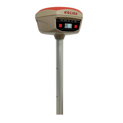
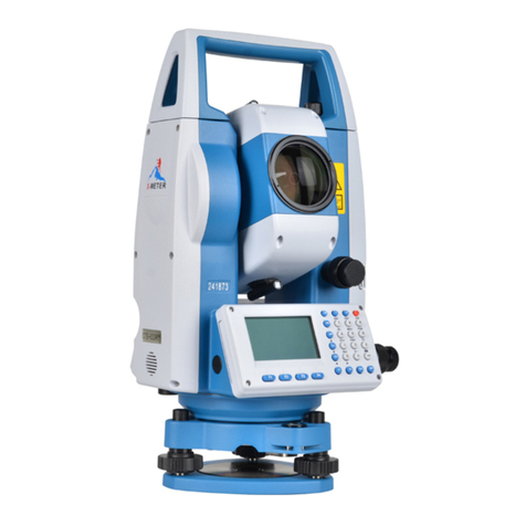
Kolida Total Station KTS-462R10L User manual

www.kolidainstrument.com
1
CONTENTS
FOREWORD........................................................................................................................................6
1. Features…...............................................................................................................................................6
2. Precautions..............................................................................................................................................7
3. Nomenclature........................................................................................................................................9
4. KeyFunctions......................................................................................................................................11
5. CharacterEntry....................................................................................................................................13
6. DisplaySymbol...................................................................................................................................14
7. ModeConfiguration...........................................................................................................................14
PART1 PREPARATION FOR MEASUREMENT............................................18
1. UnpackingandStorageofInstrument..............................................................................................18
2. Settingtheinstrumentup……….......................................................................................................20
3. Batterydismounting,information, recharging.................................................................................21
4. ReflectorPrisms……….....................................................................................................................22
5. Mounting andDismountinginstrumentfromtribrach....................................................................22
6. Eyepieceadjustmentandobjectsighting….....................................................................................23
7. Poweron/offandpreparationformeasurement….........................................................................23
7.1Poweron/off..................................................................................................................................23
7.2VerticalAngleTilt Correction......................................................................................................23
7.3Setting InstrumentOptions..........................................................................................................25
7.4Setting InstrumentConstant.........................................................................................................27
7.5SettingDateandTime..................................................................................................................28
7.6Explanations...................................................................................................................................28
PART 2 BASIC MEASUREMENTS............................................................................30
8. AngleMeasurement…………..........................................................................................................30
8.1MeasuringHorizontalAnglebetweenTwoPoints...................................................................30
8.1.1 ExampleMeasuringHorizontalAnglebetweenTwoPoints...............................................31
8.2SettingHorizonalAngletoaRequiredValue……..................................................................32
8.2.1UseHSETfunction tosetarequireddirectionValue..........................................................32
8.2.2UseHOLD tosetarequireddirectionvalue………............................................................32
8.3HorizontalAngleDisplaySelection (right/Left)......................................................................33

www.kolidainstrument.com
2
8.4 Horizontal Angle Repetition.........................................................................................34
8.5 Slope in %................................................................................................................35
9. Distance Measurement.................................................................................................................36
9.1 Settings for Distance Measurement...............................................................................37
9.2 Laser Pointer and Laser Plummet................................................................................39
9.3 Distance and Angle Measurement.................................................................................40
9.4 Review of Measured Data..........................................................................................41
9.5 OutputData to a computer...............................................................................................42
10.Coordinate Measurement.............................................................................................................43
10.1 Input Instrument Station Data.....................................................................................44
10.1.1 Reading in Registered Coordinate Data................................................................45
10.2 Azimuth Angle Setting..................................................................................................46
10.2.1 Set Backsight Point by Angle....................................................................................47
10.2.2Set BacksightPoint by Coordinate.............................................................................48
10.3 Coordinate Measurement.............................................................................................48
PART3 ADVANCED MEASUREMENT..................................................................52
11. Setting-Out Measurement.......................................................................................................52
11.1 Distance Setting-OutMeasurement............................................................................53
11.2 REM Setting-Out Measurement..............................................................................55
11.3 Coordinates Setting-Out Measurement...................................................................57
11.4 Distance Measurement Parameters Setting..........................................................60
12. Offset Measurement............................................................................................61
12.1 Single-Distance Offset Measurement.....................................................................62
12.2 Angle Offset Measurement………..........................................................................65
12.3 Two-Distance Offset Measurement......................................................................66
13. Missing Line Measurement.................................................................................................69
13.1 Measuring the distance between Multiple Targets.............................................70
13.2 Changing Start Point.........................................................................................71
14.REM Measurement...................................................................................................................72
15. Resection Measurement......................................................................................................73
15.1 Re-Observing......................................................................................................76
15.2 Add Known Point....................................................................................................77
16. Area Calculation................................................................................................................78
17. Setting out Line..........................................................................................................81
17.1 Defining Baseline.........................................................................................................81
17.2 Setting-out Line (point)...............................................................................................83

www.kolidainstrument.com
3
17.3 Setting-out Line (Line)...................................................................................................84
18. Point Projection..............................................................................................................86
18.1 Defining Baseline..........................................................................................................86
18.2 Point Projection......................................................................................................87
19. Road Design and Setting-Out...............................................................................................88
19.1 Road Design............................................................................................................88
19.1.1 Define Horizontal Alignment......................................................................88
19.1.2 Edit Alignment…….......................................................................................93
19.1.3 Define Vertical Curve.......................................................................................94
19.1.4 Edit Vertical Curve.......................................................................................96
19.1.5 Import Horizontal Alignment..........................................................................97
19.1.6 Import Vertical Curve.......................................................................................98
19.1.7 Receiving Horizontal Alignment Data...........................................................98
19.1.8 Receiving Vertical Curve Data.............................................................100
19.1.9DeletingHorizontalAlignmentData…….....................................................101
19.1.10 Deleting Vertical Curve Data........................................................................102
19.2 Road Setting-out......................................................................................................102
19.2.1 Set Station Point...............................................................................................103
19.2.2 Set Backsight Point..........................................................................................105
19.2.3 Setting-out......................................................................................................107
19.2.4 Slope Setout...........................................................................................110
PART 4 DATARECORDING.............................................................................................113
20 SETTING IN MEMORY MODE......................................................................................114
20.1 Working Job..................................................................................................114
20.1.1 Current Job Selection.....................................................................................114
20.1.2CheckMemoryStatus....................................................................................115
20.1.3 Create New Working Job………................................................................116
20.1.4 Changing Job Name…………...................................................................117
20.1.5 Delete Job........................................................................................................117
20.1.6 Coordinate Selection……........................................................................118
20.1.7 Job Export....................................................................................119
20.1.8 Coordinate Import………...................................................................120
20.1.9 Comms Send.................................................................................121
20.1.10 Comms Receive................................................................................122
20.1.11 Transfer Coordinate data to Job……........................................................123
20.2 Import Known Point Data......................................................................................124

www.kolidainstrument.com
4
20.2.1InputKnownPointCoordinate.....................................................................124
20.2.2KnownCoordinateDataImport...................................................................125
20.2.3 Known Coordinate Data Export...................................................................126
20.2.4 Receive Coordinate Data from Computer................................................126
20.2.5 Sending Known Point Data to Computer.................................................127
20.2.6 Clearing Coordinate Data from Memory……..........................................128
20.3 Input Codes.........................................................................................................128
20.3.1 Codes Import............................................................................................129
20.3.2 Receive Codes........................................................................................130
20.3.3 All Clear………..........................................................................................130
20.4 Disk Mode...................................................................................................131
20.5 Initialization..................................................................................................132
20.6SettingforGridFactor…..............................................................................................133
21 DATA RECORDING IN RECORD MODE..................................................................135
21.1 Recording Instrument Station Data..........................................................................135
21.2 Recording Backsight Data…………..................................................................137
21.2.1 Set Backsight Point by Angle………........................................................137
21.2.2 Set Backsight Point by Coordinate…......................................................138
21.3 Recording Angle Measurement Data...........................................................139
21.4 Recording Distance Measurement Data....................................................140
21.5 Recording Coordinates Data…………................................................................142
21.6 Recording Distance and Coordinate Data.........................................................144
21.7 Reviewing Job Data…………...............................................................................145
PART 5 MEASUREMENT OPTION SELECTION.......................................147
22 KEY FUNCTION ALLOCATION..................................................................................147
22.1 Allocation and Registration…..................................................................................148
22.1.1 Allocating Functions...........................................................................149
23 INSTRUMENT PARAMETERS SETTING...................................................................151
23.1 Changing Instrument Parameters............................................................................151
PART 6 CHECKING AND ADJUSTMENT...................................................155
24.1 Plate Vial…………............................................................................................................155
24.2 Circular Level..........................................................................................................155
24.3 Inclination of Reticle....................................................................................................156
24.4 Perpendicularity of Collimation Line to Horizontal Axis(2C)........................157

www.kolidainstrument.com
5
24.5 Vertical Index Difference Compensation...................................................................158
24.6 Adjustment of Vertical Index Difference (i angle) and Vertical Angle 0 Datum.....159
24.7 The Adjustment of Horizontal Axis Error Correction..............................................161
24.8 Optical Plummet........................................................................................................162
24.9 Instrument Constant (K).....................................................................................................163
24.10 Parallel between Collimation Line and Emitting Photoelectric Axis......................164
24.11 Reflectorless EDM................................................................................................164
24.12 Tribrach Leveling Screw....................................................................................................165
24.13RelatedParts forReflector………...................................................................................165
25 SPECIFICATION..........................................................................................................................166
26 ERROR DISPLAYS............................................................................................................168
27 ACCESSORIES...............................................................................................................................169
APPENDIXA:DATATO IMPORTANDEXPORT.........................................................................170
APPENDIX B: BIDIRECTIONAL COMMUNICATION.......................................................174
1.1 Output Commands.....................................................................................................174
1.2 Input Commands.............................................................................................181
1.3 Set Commands.......................................................................................................184
APPENDIX C: CALCULATE ROAD ALIGNMENT.............................................................185
1.1 Road Alignment Elements......................................................................185
1.2 CalculationofRoadAlignmentElements…………........................................................187

www.kolidainstrument.com
6
FOREWORD
Thankyou forpurchasingKOLIDATotalStationKTS-462R10L!
Thismanualis applicableforKOLIDATotal StationKTS-462R10L.
1. FEATURES
1.CompleteFunction
KOLIDA KTS-462R10L has complete surveying program and the functions of data record and
parametersetting,issuitableforprofessionalsurveyandconstructionsurvey.
2.SecureDigitalmemorycard(SDcard)
With the advantages of large memory storage, rapid transmission data system, removable and
secure functions, various surveying data could be easily saved in the SD card and moved into
computer through the port of lap top computer and card reader. Please do not move out the SD
card when writing or reading data into/ from it, otherwise the surveying data can be damaged. 1
MB space inSD cardmaycontains 15,000data.
3.PowerfulMemoryManagement
Verylargememoryandtheenhancedfile managementsystemcanhelp youeasilyrealizethe
functionofaddition,deletion,modification,andtransmissionofthedata.
4.AbsoluteEncodingDisk
With absolute encoding system, measurement can be started immediatley after booting up the
instrument. No azimuth informationisever lostevenin suddenpower break.
5.ReflectorlessDistanceMeasurement
The reflectorless function of KTS462R10L enables you to carry out long-distance and
high-accuracy measurement directly towards various objects ofdifferent materials and colors (like
wall of building, telegraph pole, wire, cliff, mountain, clay, wooden stake, etc.) It‟s the best solution
to measurethehard-reachorunreachabletarget.
6.AbundantSurveyingPrograms
KTS-462R10Lnotonlyhasthebasicsurveyingprogramss(angle,distance,coordinate
measurement)butalsoequippedwithspecialsurveyingprograms,forexample,REM,Offset,
MLM,Staking-out,RoadDesign,PointProjection,Setoutline,etc,to meetthedemandof
professionalsurvey.

www.kolidainstrument.com
7
2. PRECAUTIONS
1. Never place instrument directlyon the ground,as sand or dust maycause damage to the screw
holesorthecenteringscrewonthebaseplate.
2. Beforecarryonthemeasurement,we need to haveanoverallcheckwiththeinrsrument, suchas:
battery, parameters,andinitialsettings.
3. When working in a sun-baked (rainy or wet) day, please use the surveying umbrella to avoid
damage.Besides,donotaimthetelescope atthesun withoutafilter.
4.Whentheinstrumentisnotinuse,putitinthecaseandkeep the instrumentfromshock,dustand
humidity.
5. If there is great difference between the temperature in working area and that in storage place,
leavetheinstrumentinthecasetillitisusedtothetemperatureofoutsideworkingarea.
6.Cleanitssurfacewithawoolenclothafterusing.Iftheinstrumentgetswet,dryitimmediately.
7. Turn the power off before removing the battery, otherwise it may cause damage to internal
circuit. When place KTS into its case, firstlypower off it. Make sure that the inside of the carrying
caseandKTSaredrybeforeclosingthecase.
8. In case of not using total stationfor along time, rememberto recharge thebattery once a
month.
9.Cleanexposedopticalpartswithdegreasedcottonorlenstissueonly!
10. During transporting, the instrument should be placed in its carrying case. It will be better to
place some cushionaroundthecase to keep theinstrumentfromthe damage of shock.
11. If there is something wrong on the instrument, please do not disassemble the instrument unless
youareaprofessionalservicetechnician.
12.NeveraimthelaserbeamofKTS-462R10LTotalStationathumaneyes.
SAFETYGUIDE
InteriorEDM(VisibleLaser)
Warning:
The total station is equipped with an EDM of a laser grade of 3R/Ⅲa, which could be recognized
bythe following labels:
On the vertical tangent screw, there is a label shows “3ALaserProduction”. A similar label is on the
oppositeside.
This product is classified as Class 3R laser product, which is coordinated with the following
standards. IEC60825-1:2001“SAFETY OF THE LASER PRODUCT”.
Class 3R/Ⅲa laser product: It is harmful to observe laser beam continuously. User should avoid
sighting the laser at the eyes. It can reach 5 times the emitting limit of Class2/ II with a wavelength
of400nm-700nm.

www.kolidainstrument.com
8
Warning:
Continuouslylookingstraightatthelaserbeamisharmful.
Prevention:
Donotstareatthelaserbeam,orpointthelaserbeam to others‟ eyes. Reflected laser beam is a
validmeasurementtotheinstrument.
Warning:
When the laser beam is shooting at prism, mirror, metal surfaceor window, thereflected laser
beamisalsoharmfultoeyes.
Prevention:
Do not stare at the locations of laser reflection. When the reflectorless function is enabled on
EDM,donotstarebesidethelaserbeamorprism.Observatetheprismviathetelescopeonly.
Warning:
IncorrectapplicationofClass3Rlaserequipmentisverydangerous.
Prevention:
To avoid being hurt, youmust payparticular attention to the precaution measuresand keep it
undercontrolwithinthedistanceofpossibledangeraccordingtostandardIEC60825-1:2001.
ThefollowingexplainthekeysectionsoftheStandard:
Laser instrument of Class 3R is applicable outdoors and in construction field (measurement,
defininglines,leveling).
a) Onlythose persons who are trained with related course and authenticated are allowed to install,
adjust,andoperatethiskindoflaserinstrument.
b)Relevantlaserwarningsymbolsshouldbeeasilyidentifiedwithintheoperatingarea.
c)Preventanypersonto lookstraightatoruseopticalinstrumenttoobservethelaserbeam.
d) Toprevent the harmcausedby laser, block thelaserbeamatthe end ofthe working route. When
the laser beam exceeds the limit area (harmful distance*) and when there are motivating persons,
stoppingthelaserbeamisamust.
e)Theopticalpathofthe lasershouldbe sethigherorlower thanthelineof sight.
f) When the laser instrument is not in use, take care of it properly. The person who is not
authenticatedisnotallowed touse.
g) Prevent the laser beam from irradiating plane mirror, metal surface, window, etc., especially
bewareofthesurfaceofplanemirrorandconcavemirror.
* Harmful distance means the maximum distance between the start point and the point which the
laser is weakened to a degree that doesn‟t harm people.
* The harmful distance of built-in laser unit is 1000m (3300ft). When the operation is beyond this
rangeandlaserbeamis weakenedtoClass1R,directstaringatlaserbeamislessharmful.

www.kolidainstrument.com
9
3. NOMENCLATURE
Collimator
ObjectiveLens
PlateLevel
Battery
Batterylocking
Screen
HorizontalClamp Screw
HorizontalTangentScew
SD CardReader
Mini USBport
BasePlate

www.kolidainstrument.com
10
TribrachFixingScew
CenterMark
TelescopeFocusingKnob
Eyepiece
VerticalClampScrew
VerticalTangentScew
Keyboard
CommunicationPort
CircularLevel
LevelingScrew

www.kolidainstrument.com
11
4. KEYFUNCTIONS
·PowerON/OFFKey
PowerON :Press POWER for2seconds
PowerOFF :Press POWER for3 seconds
·SoftKey
The functions of soft keys are showed on the bottom of the display window of KTS-462R10L,
select these functions by using F1 to F4 keys, press Direction key to view other functions in
anotherpage.
Forexample,thefollowingshowstheinitialsettingofthesoftkeysdisplayedinMEASmode
Page1 :
Name
Function
DIST
Start distance measurement (SD,VD, Angle)
D/C
Select distance measurement category(change between
distance and coordinate)
0SET
Set the horizontal angle to 0
HSET
Set the horizontal angle to a required value
BackSpace
Help
NumberKey
Enter
ESC
DirectionKey
StarKey
SoftKeyF1-F4
InputTargetHeight
Power
Alpha-NumericSwitch

www.kolidainstrument.com
12
Page2 :
Name
Function
R/L
SwitchbetweenHorizontalLeftAngle andRightAngle
REP.
Makeanglerepetitionmeasurement
HOLD
Lockhorizontalangle
ZA/%
Switchvertical angledisplaymethod
Page3 :
Name
Function
HT
Setinstrumentheight andtargetheight
REC.
EnterRECORDmenu
REM
EnterRemoteMeasurement
MLM
MissingLine
OperatingKeys:
Name
Function
BS
Deleteablankleft
IM
Switchnumberinputandalphabetinput
REC
1. Enable target-height inputting in staking-out, missing line, and remote
measurement.
2.EnterRECORDmenu.
HELP
Show KOLIDA web address
ESC
Cancelpreviousoperationandreturntopreviousscreen
ENT
Confirmto entryor save data on that line and move the cursor to the next
line.
F1~F4
Refer to the screen display (key function setting)
0~9
Numerical/Alphabetinput/Selectionmenuitem
²~-
Inputdecimalpoint: .
Inputsymbol: \ #
Inputminussymbol: -+
▲
Movecursor/selectoptionsup
viewthepreviousdataindatalist
▼
Movecursor/selectoptionsdown
viewthenextdataindatalist
Movecursortotheleft/Selectanotheroptions
viewthepreviouspageindatalist

www.kolidainstrument.com
13
Movecursortotheleft/Selectanotheroptions
viewthenextpageindatalist
5. CHARACTER ENTRY
Jobnames,datanumbers,codes,etcareenteredtoKTS-462R10Lusinglettersofalphabetand
numerals.
Changebetweenalphabeticandnumericalentrybypressing IM key.An isdisplayedonthe
rightsideofthescreenwheninalphabetentrymode.
Alphabet entry mode ←IM→ Numeral entry mode
Entryinalphabetandnumeralmodeisperformedasfollows:(Eg :CharacterentryJOBM2)
Procedure
Operation
Display
1) Enter Alpha-numeric input mode, each key
standsforthreealphabets andonenumber.
Pressthekey,thefirstalphabetwill beshownonthe
cursorposition.Pressthekeybyfourtimes,the
numberwillbeshown.
AlphaKey
AddCode
INDEX:0
CODE:JOB
OK
2) Press IM toenternumeralinputmode.
IM
AddCode
INDEX:0
CODE:JOB-1
OK
3) When the entry is finished, press OK. The
originalscreenis restored.
AddCode
INDEX:0
CODE:JOB-1
OK

www.kolidainstrument.com
14
6. DISPLAYSYMBOLS
Somesymbols areusedin MEASmode.Their meaningsarepresentedbelow.
Symbol
Meaning
PC
Prismconstant
PPM
Atmosphericcorrection
ZA
Zenithangle(Zenith0°)
VA
Verticalangle(horizontal0°/horizontal0°±90°)
%
Slopein%
S
Slopedistance
H
Horizontaldistance
V
Heightdifference
HAR
Horizontalangle right
HAL
Horizontalangleleft
TiltCompensationisturnedON
7. MODECONFIGURATION
KTS-462R10L operates in a series of modes depending on your measurement need. This section
explains the relationship between the different modes and presents tables of the menus for each
mode.
·ModeDiagram
HomePage
MEASUREMENT
MEMORY
MENU
CONFIG

www.kolidainstrument.com
15
1. ModeDiagram
MEM
ESC
CNFG
ESC
MEAS
MENU

www.kolidainstrument.com
16
2. MenuList
①MEASmodemenu
Name
Function
DIST
Distancemeasurement
D/C
Displayswitchbetweendistanceandcoordinate
0SET
Sethorizontalangleto0
HSET
Setknownhorizontalangle
R/L
Selecthorizontalangleright/Left
REP
Horizontalanglerepetitionmeasurement
HOLD
HorizontalangleHold/Release
ZA/%
SwitchbetweenZenithangle/slopein %
HT
Settheinstrumentheightandtargetheight
REC
Datarecording
REM
REMmeasurement
MLM
MLMmeasurement
RCL
Displayfinalmeasurementdata
VIEW
Displayobservationdataforthe selectedJOB
EDM
SettingEDM (atmospheric correction and target,distance measurement mode
setting)
CRD.
Coordinatesmeasurement
S-O
Setting-outmeasurement
OFFS
Offsetmeasurement
MENU
Tomenumode
RESE
Resectionmeasurement
DOUT
Outputmeasurementresulttoexternalequipment
F/M
Switchbetweenmeters/feet
AREA
Areacalculation
ROAD
DesignandSetoutroad
PROJ
PointProjection
LINE
LineSetout

www.kolidainstrument.com
17
② RECModeMenu
Name
Function
Stndata
Occupiedstationdatarecording
Backsightdata
Recordbacksightbearingangleandcoordinatedata
Angledata
Anglemeasurementdatarecording
Distdata
Distancemeasurementdatarecording
Coorddata
Coordinatesmeasurementdatarecording
Dist+ Coord.
Recorddistanceandcoordinatedata
View
Reviewjobdata
③MEM ModeMenu
Name
Function
JOB
JOBselectionandmanagement
Knowndata
Knowndatainputandmanagement
Code
Codeinputandmanagement
Disk
Check/Formatmemorydisk
Backup
Check/Editbackupdata
Card Reader
ConnecttotalstationtoPCasathumbdrive
Gridfactor
Gridfactor

www.kolidainstrument.com
18
PART1PREPARATIONFORMEASUREMENT
1. UNPACKINGANDSTORAGE OFINSTRUMENT
· UnpackingInstrument
Placethecaselightlywiththecoverupward,andunlockthecase,takeout theinstrument.
·StoringInstrument
Cover the telescope well, place the instrument into the case with the vertical clamp screw and
circularlevelupward(Objectivelens toward tribrach),tighten theverticalclamp screwand lock the
case.
2. SETTINGTHE INSTRUMENTUP
Place the instrument on the tripod. Level and center the instrument precisely to ensure the best
performance.Usetheprofessionalsurveyingtripod.
1. Settingupthetripod
①Makesurethelegsarespacesatequalintervalsandtheheadisapproximatelylevel.
②Setthetripodso the center of thehead is directlyoverthe surveyingpoint.
③Step onthe tripodshoesto makesure the tripodisfirmlyfixed onthe ground.
2. Installingtheinstrumentonthetripod
①Placetheinstrumentcarefullyonthetripodhead
②Supporting the instrument with one hand, tighten the centering screw to fix it to the
screwonthebaseplateoftheinstrument.
3. Roughlylevelingtheinstrumentbythecircularlevel
①Turntheleveling screwAand Bto movethe bubblein the circularlevel,inwhichcase the
bubble is located on a line perpendicular to a line running through the centers of the two
levelingscrewbeingadjusted.
②RotatelevelingscrewCtocenterthebubble.

www.kolidainstrument.com
19
4. Levelingbytheplatelevel
①Rotate the instrument horizontally by loosening the Horizontal Clamp Screw and place
theplatelevelparallelwith thelineconnectinglevelingscrewAandB,andthenbringthe
bubble tothecenteroftheplatelevelbyturning theleveling screwsAandB.
②Rotate the instrument 90º(100g) around its vertical axis and turn the remaining leveling
screw orlevelingCto centerthebubbleonce more.
③Repeat the procedures ①② for each 90º (100g) rotation of the instrument and check
whetherthebubbleiscorrectlycenteredin alldirections.
5. Centeringby usingtheopticalplummet
1) Settripod
Lifttripodtosuitableheight,ensureequal lengthofthreelegs,spread and make tripodheadparallel
to theground,and place it rightabove the measurement stationpoint.Propup tripod on theground
andfixoneleg.
2) Install instrumentand collimate thepoint
Set instrument carefully on tripod, tighten the centralconnecting screw and adjust optical plummet
to makethereticledistinctly.Holdtheothertwounfixed legswith bothhands andadjustpositionof
these twolegs through observation ofopticalplummet.Asitapproximatelyaims atthestationpoint,
make all three legs fixed on the ground. Adjust three leg screws of the instrument to make optical
plummetcollimatepreciselytothe stationpoint

www.kolidainstrument.com
20
3)Use circular vialtoroughlyleveltheinstrument
Adjustlength ofthree legsoftripod, makethecircularvialbubbleoftheinstrumentinthemiddle.
4)Use platevialtoleveltheinstrumentaccurately.
①Rotatethe instrument horizontallyby loosening the Horizontal Clamp Screw and place the plate
vialparalleltothelineconnectinglevelingscrewAandB,andthenbringthebubbleto thecenterof
theplatevialbyturning theleveling screwsAandB.
②Rotatetheinstrument90‵, makeit perpendiculartotheconnecting lineoflevelscrewsAandB.
TurnlevelscrewCtomakethebubbleoftheplate vialin the middle.
5)Preciselycenteringandleveling
Throughobservationofopticalplummet,slightlyloosenthecentralconnectingscrewandmovethe
instrument evenly (Don‟t rotate the instrument), making the instrument precisely collimating to the
stationpoint.Thentightenthecentralconnectingscrewandleveltheinstrumentpreciselyagain.
Repeatthisoperation tilltheinstrumentcollimatepreciselytothemeasurementstationpoint.
3.BATTERYDISMOUNTING,INFORMATION,RECHARGING
·BatteryRemovalCaution
☆Before taking the battery down, make sure that the power is turned off. Otherwise, the
instrumentcanbedamaged.
PROCEDURE Insertingthebattery
1.Putthebatteryonthemainbodyofinstrument.
2. Pressthelockingbuttons onthetopofbatteryto lockit.
PROCEDURE Removingthebattery
1.Presstheclampsonthetopofthebattery.
2.Takeoffbattery.
·BatteryPowerRemainingDisplay
3-5:70~100﹪Fullpower
2:50﹪batterypowercanlastfor almost1 hour
1:10~50﹪itisbettertofinishmeasuringsoon,rechargeit.
0:0~10﹪batterycanlastonlylessthan 10minutes only
Note: ①Working time of the battery is determined by environment condition, recharging time
andetc.
②Theremainingenergylevelofbatteryisrelated tocurrentmeasuring mode.
MEAS(1/3)
SHV
S
H
V
VA 273°18′15″
HAR 150°18′15″P1
DIST D/C 0SET HSET
Table of contents
Other Kolida Measuring Instrument manuals

Kolida
Kolida K1 Pro User manual

Kolida
Kolida K3 IMU User manual

Kolida
Kolida KL-15 User manual

Kolida
Kolida KTS-442UT Series User manual

Kolida
Kolida KTS-470 R Series User manual

Kolida
Kolida DL-200 User manual

Kolida
Kolida KL-03 User manual

Kolida
Kolida KTS440 R Series User manual

Kolida
Kolida CTS-632R10M User manual

Kolida
Kolida K20s User manual
Popular Measuring Instrument manuals by other brands

Liverage
Liverage Fiber Checker User manual and specifications

Badger Meter
Badger Meter ModMAG M Series user manual

BANTE inststruments
BANTE inststruments 210 instruction manual

Acrel
Acrel GGF Series Installation and operation manual

Alti-2
Alti-2 Altimaster Series owner's manual

Danfoss
Danfoss EKC 201 manual