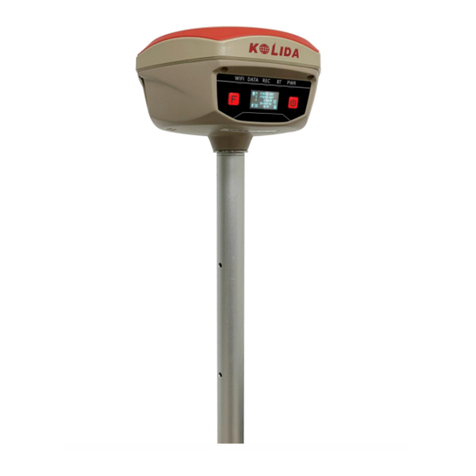
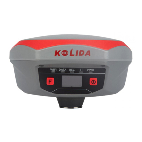
Kolida K3 IMU User manual

K3 IMU
- 1 -
KOLIDA K3 IMU Positioning System
User Guide

K3 IMU
- 2 -
Contents
Contents.......................................................................................................................................- 2 -
ChapterⅠPreface.........................................................................................................................- 4 -
§1.1 Introduction .................................................................................................................- 4 -
§1.2 Applications .................................................................................................................- 4 -
§1.3 Main Features ..............................................................................................................- 5 -
ChapterⅡHardware Introduction ...............................................................................................- 7 -
§2.1 Bottom Components ....................................................................................................- 8 -
§2.2 Indicator and buttons ...................................................................................................- 9 -
§2.3 Check the remaining power .........................................................................................- 9 -
§2.4 Check and switch working mode...............................................................................- 10 -
§2.5 Receiver self-check....................................................................................................- 10 -
§2.6 Factory reset...............................................................................................................- 10 -
ChapterⅢWeb UI Management ............................................................................................... - 11 -
§3.1 Overview ................................................................................................................... - 11 -
§3.2 Access by WiFi .......................................................................................................... - 11 -
§3.3 Access by USB ..........................................................................................................- 12 -
§3.4 Web UI main interface ...............................................................................................- 13 -
§3.4.1 Status...............................................................................................................- 14 -
§3.4.2 Configuration..................................................................................................- 16 -
§3.4.3 Satellite Information .......................................................................................- 21 -
§3.4.4 Data Record ....................................................................................................- 22 -
§3.4.5 Data Transfer ..................................................................................................- 24 -
§3.4.6 Network Config ..............................................................................................- 27 -
§3.4.7 Radio Config...................................................................................................- 30 -
§3.4.8 Firmware Update ............................................................................................- 31 -
§3.4.9 Track Manage .................................................................................................- 32 -
§3.4.10 Coordinate System(reserve)..........................................................................- 34 -
§3.4.11 Online Service(reserve) ................................................................................- 34 -
§3.4.12 User Management.........................................................................................- 35 -
§3.4.13 System log ....................................................................................................- 35 -
ChapterⅣAccessories...............................................................................................................- 36 -
§4.1 Instrument Case .........................................................................................................- 36 -
§4.2 Charger &Adapter......................................................................................................- 36 -
§4.3 Differential Antenna ..................................................................................................- 37 -
§4.4 Cables ........................................................................................................................- 37 -
§4.5 Other Accessories ......................................................................................................- 37 -

K3 IMU
- 3 -
Appendix A KOLIDA K3 IMU technical specifications ...........................................................- 38 -
Appendix B Technical Terms.....................................................................................................- 39 -
FCC Statement...........................................................................................................................- 40 -

K3 IMU
- 4 -
ChapterⅠPreface
In this chapter you will have a brief knowledge of KOLIDA Company and K3 IMU
measurement system.
§1.1 Introduction
Welcome to KOLIDA Instruments Co., Ltd, which is China’s leading manufacturer of surveying
equipment including GNSS receivers and Total Stations, etc. To know more about KOLIDA,
please visit our official website http://www.kolidainstrument.com/.
In the guide, we'll show you how to operate the K3 IMU RTK system as well as the accessories.
We recommend you to read the guide carefully before getting started.
§1.2 Applications
Control Survey: static measurements can accurately complete the high-precision deformation
observation, photo-control point measurement.
Highway Survey: quickly complete the encryption of the control points, road topographic
mapping, cross-section measurement, profile measurement with K-survey.
CORS Application: provide more stable and convenient data link for field operations. It is
seamlessly compatible with all types of domestic CORS applications.
Data acquisition measurement: perfect match KOLIDA’s various measurement software to do
quick and easy data acquisition.
Stakeout shot:large-scale point, line, plane lofting.
Electric Power Measurement:power line measurement orientation, ranging, angle calculation.
Marine application:oceanographic research, dredging, piling, inserted row, making the marine
operations convenient and easy.

K3 IMU
- 5 -
§1.3 Main Features
Best-in-Class GNSS Signal Tracking
The integrated advanced 965-channel GNSS technology helps K3 IMU to collect signal from
GPS, Glonass, Beidou, Galileo, QZSS, in particular the latest BeiDou III. It greatly improved the
data quality and satellite signal capturing speed of GNSS surveying.
A Huge Leap in Working Hours
Thanks to the high-capacity battery and the intelligent power management plan. K3 IMU can
work up to 12 hours in RTK radio rover mode, up to 15 hours in static mode. The charging port is
Type-C USB, users can choose KOLIDA quick charger or their own smartphone charger or power
bank to recharge.
Constantly Updated GNSS + IMU Technology
The K3 IMU is equipped with KOLIDA’s 3rd generation inertial sensor and algorithm. The
working speed and stability have been improved for 30% from the last version. When the GNSS
fixed solution is lost and recovered again, Inertial sensor can remain the working status in a few
seconds, no need to spend time to reactivate it.
A Lightest Receiver, Comfortable Experience
K3 IMU is an ultra light GNSS receiver that leaves the competition behind. Its total weight is only
0.69 kg including battery, 40% even 50% lighter than a traditional GNSS receiver. The
light-weight design reduces surveyor’s fatigue, increase their mobility, is especially helpful to
work in challenging environment.
More Intelligent SOC Platform
“SOC”, System-On-Chip technology features highly integration, faster computing speed, and
stronger processing capabilities that improve RTK performance and work efficiency. The receiver
can be much lighter and smaller. The power consumption is low, receiver can work 12-15 hours.
The “High-Low Integration” antenna can effectively restrain the interruptive signal.

K3 IMU
- 6 -
Advanced UHF module
KOLIDA K3 IMU enjoys a new and excellent datalink system, which is compatible with current
radio protocols in the market, and realizes the random switching of the radio range
410MHZ-470MHZ. “Farlink”technology improves the signal-catching sensitivity from -110db
to-117db, so K3 IMU can catch the very weak signal from a base station far way.
Internal Web UI management
Embedded Web UI management platform supports WIFI and USB mode connection. Users can
monitor the receiver status and configure it via the internal Web UI management platform.
Bluetooth and NFC
KOLIDA K3 IMU is equipped with dual-mode Bluetooth v4.0 standard which is able to connect
the other smart devices and compatible with Bluetooth v2.1 standard. It not only enlarges the
work range but also makes the data communication become more stable. The internal NFC
module can make the complicated Bluetooth communication easy and simple.
WiFi
As the new feature and technology adopted on K3IMU, it not only can be used as data link to
access to internet, but also can be as a hotspot which can be accessed by any other smart devices
to configure the receiver.
Intelligent Storage
The raw data including STH, Rinex2.01 and Rinex3.02 not only can be saved in the internal
memory (8G SSD), but also can be stored into an external USB device (OTG). The configurable
sample frequency is really up to 20Hz.

K3 IMU
- 7 -
ChapterⅡHardware Introduction
Reading this chapter, you can grasp the components, installation and the function of
KOLIDA K3 IMU measuring system.
The receiver is round and flat with height of 60mm and diameter of 137mm. It looks elegant,
strong and durable. And it adopts a combination design of voice and buttons, easier to operate.
The bottom of the receiver has commonly used interfaces.

K3 IMU
- 8 -
§2.1 Bottom Components
Component
Description
Speaker
Mode setting and working status prompt
SN label
Apply for a registration code, Bluetooth ID
Battery indicator
Real-time indication of battery level.
USB interface
1. USB for data transmission and Ethernet port for login web
interface.
2.Battery charging port.
UHF antenna interface
Install UHF antenna.
5-pin LEMO port
1.As a power port connected with an external power supply
device.
2. As a differential transmission port connected with an
external radio.
3.As a serial port to check data output and debug.
5-Pin
LEMO Port
USB interface
UHF antenna
interface
Speaker
Serial number
Label
Battery
indicator

K3 IMU
- 9 -
§2.2 Indicator and buttons
Control Panel
Ref
Component
Description
Power Button
1.Power on/off receiver.
2.Confirm working mode and data link.
3. Perform general settings on the receiver.
4. Always on when power on, flashing on low power.
Data Indicator
Rover Mode: Flashes red light when the correction
data is received but not Fixed solution.
Flashes green light after getting Fixed solution.
Base Mode: Flashes red light when there is differential
data transmission.
Static mode: Flashes by the data sampling interval to
indicate the data file is recording.
Bluetooth
Indicator
Glows in blue to indicate that Bluetooth connection has
established between controller and receiver.
§2.3 Check the remaining power
When K3 IMU is charging, the corresponding light flashes before charging to the corresponding
power. Press the power button once, the current battery level will show several lights.
For example, when the battery is fully charged, the four lights of 25%, 50%, 75%, and 100% are
all green on. When the battery is 60%, press the power button once, and the 25% and 50%
indicator lights will be red on.

K3 IMU
- 10 -
§2.4 Check and switch working mode
1. Check work mode
When K3 IMU is working normally, press the power button once, and then there will be voice
broadcast of the current working mode.
2. Switch work mode
Press and hold the power button for more than six seconds to broadcast the "Start to set work
mode" voice, then release the power button. At this moment, K3 IMU will say “Rover mode, Base
mode and Static mode”one by one, when you hear the working mode you need, press power key
to confirm.
§2.5 Receiver self-check
Self-check is a useful operation to simply check the main hardware components if the instrument
is abnormal or not working properly.
Press and hold the power button for about 10 seconds and pass over the state of power off and
mode selection (do not release the power button even the instrument says power off and start to
set work mode), then K3 IMU will say “start to self-check”, at this moment, release power button,
the instrument will perform self-check automatically for the modules one by one.
The sequence of modules checking is:
* OEM board checking * UHF module checking * Sensors checking
* WIFI module checking * Bluetooth module checking
If all the modules are normal during self-check, the instrument will get into the state of power-on.
§2.6 Factory reset
Press and hold the power button for about 20 seconds and pass over the foregoing states (power
off, start to set work mode and self-check), K3 IMU will get into factory reset progress with voice
message saying “start to restore factory default”, at this moment, release power button, the
instrument will perform factory reset automatically. After this progress complete, the instrument
will restart automatically with the factory default settings.
Video: https://www.youtube.com/watch?v=zuxUCUZs_E4

K3 IMU
- 11 -
ChapterⅢWeb UI Management
§3.1 Overview
Because of using the smart embedded Linux operating system and KOLIDA intelligent cloud
technology, the web UI allows users to configure and monitor the status of K3 IMU in real-time.
The accessing way is not only by WIFI connection, but also can be USB mode.
§3.2 Access by WiFi
The WIFI hotspot is default broadcasted by K3 IMU, search the WIFI hotspot which named with
KOLIDA_xxxx using smartphone, tablet or laptop, then establish the WIFI connection, input the
default IP (10.1.1.1) into broswer, on the login interface, apply “admin”for the username and
password.
For example, search the WIFI hotspot broadcasted by a KOLIDA receiver using a laptop PC,
choose the WIFI hotspot and click on connect button to establish the connection without
password.
Run IE broswer on computer and input the default IP (10.1.1.1)into address bar, after a while, the
system login interface is refreshed, then apply “admin”for username and password to login.

K3 IMU
- 12 -
§3.3 Access by USB
On this mode, the type-C USB port of K3 IMU works as an Ethernet port, then internal web UI
shall be accessed via USB cable connection with computer.A corresponding driver is required to
install to the computer, then this function could be activated. You can contact with KOLIDA
technician for the driver and support.
Run IE broswer on computer and input the default IP (192.168.155.155)into address bar, after a
while, the system login interface is refreshed, then apply “admin” for username and password to
login.
IP Address: 10.1.1.1
Username: admin
Password: admin
IP Address: 192.168.155.155
Username: admin
Password: admin

K3 IMU
- 13 -
§3.4 Web UI main interface
After login the Web UI management of K3 IMU by WIFI or USB connection, the main interface
appears with displaying configuration items and positioning. As shown at following figures.
In the Web UI home page, the configuration items are listed at left side. And the positioning
informaiton including coordinates information and satellites are diplayed at right side.
Ref
Component
Description
Status
Positioning information, satellite tracking and the others will
be displayed in this page
Configuration
It contains registration for receiver, base configuration,
antenna configuration, satellite configuration, receiver
configuration and system configuration.
Satellite Information
Display and control the satellites are used or not
Data Record
Configure the parameters for static mode and raw data
download
Data Transfer
Contains NTRIP configuration, TCP/IP configuration and data
transferring with PC

K3 IMU
- 14 -
Network Config
WIFI configuration and the other functions
Radio Config
Configure the parameters and frequency for radio modem
Firmware Update
It is used to upgrade the firmware for receiver and each
modem
Track Manage
Record track file while doing measurement
Coordinate System
Setup a local coordinate system for K3 IMU
Online Service
Upload data onto a server in real-time
User Management
Add and manage the Web UI users
Help
Offers solutions
§3.4.1 Status
System Information, Work Status and Position Information are listed under Status menu.
System Information
In this page, all the information of K3 IMU is diplayed such as serial number, hardware ID, MAC
address, firmware version and so on.

K3 IMU
- 15 -
Work Status
The physical state of K3 IMU such as working mode, datalink, host temperature, remaining
power and the free memory is obtained from this page.
Position Information
In this page, users can be clear at a glance on current position information and satellite
information.

K3 IMU
- 16 -
§3.4.2 Configuration
General Config, Base Setup, Antenna Setup, Satellite Tracking, Receiver Operate and Default
Language are contained under Configuration menu. Users are able to configure all kinds of
parameters for K3 IMU under Configuration menu, and all the settings are immediate effect after
saving.
General Config
The registration for receiver working mode setting can be completed.
If K3 IMU is expired, please provide the serial number of your K3 IMU for us to apply for
another available code, then input the code into the blank or register the receiver online.

K3 IMU
- 17 -
K3 IMU allows users to setup the working mode and datalink from this Web UI that only need the
mobile phone or tablet PC is able to connect the wifi hotspot of K3 IMU.
Work Mode: There are Rover, Base and Static contained in this dropdown list.
Datalink: Pull down the list, there will be all kinds of options for datalink, such as radio, External,
Bluetooth, WIFI and CSD.
RTK Record: This is used to enable raw data recording in base mode or rover mode for
post-processing
1 PPS: This option is for the 1 pulse per second output
EVENT: This option is for the EVENT marker input
EVENT Polarity: EVENT input method.

K3 IMU
- 18 -
Base Setup (works as an internet base station)
When K3 IMU works as Base station, the basic configuration for base can be setup in this page.
Users can input the correct coordinates or capture a current position for the base. Also users can
define what kind of correction format is transmitted.
CMR ID/RTCM2.X ID/RTCM3.X ID: Users can specify the ID for transmitting correction.
Position: Click this button to capture the coordinates for current position
Spare: This is used to the repeat station
Base Start Mode: Here contains 3 methods to start the Base, manually start base, automatically
start base by fixed point, automatically start base by current point.
Correction: Here contains the global general used correction formats including RTD,RTCM23,
RTCM30, RTCM32, CMR and SCMRx
POP Value: This value is setup for the PDOP limitation.
Status: Here will display the status for base in real-time.
Antenna Setup
The antenna parameters are configured including the antenna height, measuring method.

K3 IMU
- 19 -
Antenna Height: This is the value for height of antenna while surveying.
Measuring Method: Here provides several methods for measuring the antenna height such as
carrier phase center, slant height, antenna edge, height plate and to the bottom.
Satellite Tracking
In this page, users can define the mask angle for satellite tracking, and check on the box of
corresponding band from the constellation that to use this band or not
Receiver Operation
The page provides all kinds of operations to control the receiver such as self-check operation,
clean epochs, factory reset, reboot and power off.

K3 IMU
- 20 -
Self-check: Users can also do the self-check from this configuration page, click on the Check all
button to check all the modems or click on the check button corresponding to the modem to check
one by one.
Clean EPH: Click this button to clear the remaining epochs to let recever track the satellites
better.
Factory Default: Click this button to bring the receiver back to factory default setting.
Reboot: Click this button to restart the receiver.
Power Off: Click this button to power off the receiver.
System Setup
This page is used to control Voice prompt, volume of voice, power saving and the default
language for receiver.
Voice Prompt: Check on this box to turn on the voice guide, uncheck it to turn off the voice guid.
Voice Volume: Define the voice volume for K3 IMU’s speaker.
Power: Configure the receiver to use the power saving mode or not.
USB: The Type-c interface of K3 IMU is set to USB disk and network interface mode at the same
time, no need to set up it for K3 IMU.When connected to the computer, you can open internal
memory and runweb Ui at the same time for K3 IMU.
Default Language: Configure the default language for K3 IMU which associates with voice guid.
Time Zone (h): Use this to setup the corresponding time zone for your country or area.
Table of contents
Other Kolida Measuring Instrument manuals

Kolida
Kolida K20s User manual

Kolida
Kolida KL-15 User manual

Kolida
Kolida KTS440 Series User manual

Kolida
Kolida KTS440 R Series User manual

Kolida
Kolida DL-200 User manual

Kolida
Kolida KTS-442UT Series User manual

Kolida
Kolida Total Station KTS-462R10L User manual

Kolida
Kolida K1 Pro User manual

Kolida
Kolida KTS-470 R Series User manual

Kolida
Kolida CTS-632R10M User manual