Kolver 035001 User manual

K-DUCER MANUAL
KDU-1 / KD-1A
Torque range: 0.1-15 Nm
UIDENTIFICATION DATA OF THE MANUFACTURER
KOLVER S.r.l.
VIA M. CORNER, 19/21
36016 THIENE (VI) ITALIA
UIDENTIFICATION DATA OF THE PRODUCT
MODEL: KDU-1 KDU-1A
CODE: 035001 035001/A
TECHNICAL DATA OF THE PRODUCT
FUSE: 3,15 A
DIMENSIONS: 190 x 205 x h120 mm WEIGHT: 2,5 Kg
POWER SUPPLY: 90÷260 V AC 50÷60 Hz
TENSION: 40V DC
POWER: 600W
DECLARATION OF CONFORMITY
KOLVER S.r.l. declares that the new tool here described: control units model KDU-1, KDU-1A are in
conformity with the following standards and other normative documents: 2006/42/CE, LVD 2014/35/UE,
EMCD 2014/30/UE, EN 62841-2-2:2014, EN 62841-1: 2015, EN 60204-1, EN 61000-6-2, EN 61000-6-4.
It is also in conformity with III normative (2011/65/UE and following 2015/863).
Name: Giovanni Colasante
Position: General Manager
Person authorized to compile the technical file in Kolver
Thiene, January 1st 2021
Giovanni Colasante

Vers. 291020 2
MODELS:
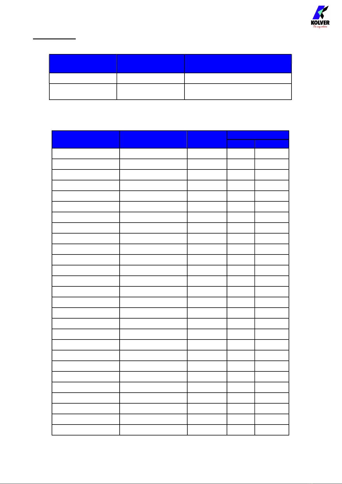
K-DUCER power supply and control units are available in two versions:
Code Model Features
035001 KDU-1
035001/A KDU-1A as KDU-1 + RJ4 connector
Modbus TCP (slave) communication protocol
They also control the torque of any KDS electric screwdrivers with transducer, available straight, pistol
and fixture configuration.
Code Model Torque (Nm)
Speed (rpm)
Min
Max
135006 KDS-PL6 0,5-6 50 850
135006/ESD KDS-PL6 0,5-6 50 850
135007/ESD KDS-PL6P 0,5-6 50 850
135007/U/ESD KDS-PL6P/U 0,5-6 50 850
135106 KDS-PL6CA 0,5-6 50 850
135106/FN KDS-PL6CA/FN 0,5-6 50 850
135006/A/ESD KDS-PL6ANG 0,5-5,5 50 850
135010 KDS-PL10 0,8-10 50 600
135010/ESD KDS-PL10 0,8-10 50 600
135011/ESD KDS-PL10P 0,8-10 50 600
135011/U/ESD KDS-PL10P/U 0,8-10 50 600
135110 KDS-PL10CA 0,8-10 50 600
135110/FN KDS-PL10CA/FN 0,8-10 50 600
135010/A/ESD KDS-PL10ANG 0,8-9 50 600
135015 KDS-PL15 0,5-15 50 320
135015/ESD KDS-PL15 0,5-15 50 320
135016/ESD KDS-PL15P 0,5-15 50 320
135016/U/ESD KDS-PL15P/U 0,5-15 50 320
135115 KDS-PL15CA 0,5-15 50 320
135115/FN KDS-PL15CA/FN 0,5-15 50 320
135015/A/ESD KDS-PL15ANG 0,5-14 50 320
175015 KDS-MT1.5 0,1-1,5 50 850
175015/ESD KDS-MT1.5/ESD 0,1-1,5 50 850
175016/ESD KDS-MT1.5P 0,1-1,5 50 850
175016/U/ESD KDS-MT1.5P/U 0,1-1,5 50 850
175115 KDS-MT1.5CA 0,1-1,5 50 850
175115/FN KDS-MT1.5CA/FN 0,1-1,5 50 850

Vers. 291020 3
K-DUCER is the new class A intelligent transducerized assembly system from Kolver.
Thanks to a sophisticated control system, the electronic circuit communicates with KDS series
screwdriver equipped with integrated torque/angle transducer and allows to stop the screwdriver
instantly when reaching the preset torque or angle.
The AC 90÷260V - 50÷60Hz power supply is converted into 40VDC required by the KDS series
screwdrivers through a switching board.
IMPORTANT: K-DUCER is a highly accurate unit but it is critically important to select the correct
options to ensure that proper torque is being applied. Read the menu description carefully and in case
you are unsure please contact Kolver for support information.
INSTALLATION:
Installation of KDU unit:
KDU control unit is supplied with a bracket.

Vers. 291020 4
On the back panel, there are four female threaded pivots 8 mm depth to be used to fix the bracket. KDU unit
is supplied with four M4x8 screws to help the plate to be fixed to the unit or to any other Kolver supports.
It is also available both a table stand (code 010400) and a vertically and horizontally adjustable bracket
(code 010401).
Installation of KDS screwdriver:
The KDS screwdrivers series require a 2.5m male/female cable (code 250064) or 5m (code 250564). Or
cables with strain relief (2.5m 250064/H and 5 m 250564/H).
To connect the cable to the unit, insert the male connector into the appropriate TOOL connector on
the bottom of the unit, taking care to respect the alignment tabs. Push the connector into its position
and turn clockwise the OPEN/CLOSE nut. Referring to the screwdriver, use the female side of the

Vers. 291020 5
cable and perform the same operations. To disconnect the connectors, apply a light pressure of the
cable connector towards the fixed connector and turn counterclockwise the nut.
Turn the unit on through the on/off switch on the lower panel. The unit will carry a general system check
and the words “NO SCREWDRIVER CONNECTED” will appear if no screwdriver is connected.

Vers. 291020 6
NB: It’s possible to enter the menu even without any screwdriver connected.
1- To enter the menu
Instead if the screwdriver is connected, it will be recognized by the unit and the "CONNECTED
SCREWDRIVER" screen will appear for a few seconds, also showing the model and serial
number.
NB. All parameters read during the recognition of the screwdriver can also be displayed in the
SETTING menu.
If the parameters set in the K-DUCER unit are outside of the range of the screwdriver, the
following screen will appear:
1

Vers. 291020 7
At this point select a different program by clicking on the "Access to the menu" button or modify
the parameter out of range.
The error messages can be the following:
TorqueTargOverMax
Target torque higher than the allowed limit for the screwdriver.
SpeedTargOverMax
Target speed higher than the limit allowed for the screwdriver.
SpeedTargUnderMin Target speed less than the limit allowed for the screwdriver (50
RPM).
DownshiftTorqueOverTarg
The
fast phase torque setting is higher than the final target torque.
DownshiftSpeedOverMax The speed of the slow phase of this program is higher than the
maximum allowed by the screwdr
iver.
DownshiftSpeedUnderMin The speed of the slow phase of this program is less than the
minimum allowed by the screwdriver (50 RPM).
TorqueMaxOverMaxLim In angle control: the maximum torque set in the program is above
the limit of the screwdriver.
In torque control: the maximum torque set in the program is higher
than 20Nm.
TorqueMaxUnderMinLim In angle control: the maximum torque set in the program is equal or
lower than the minimum limit of the screwdriver.
In torque control: The maximum torque set in the program is equal
or lower than the target torque already set.
TorqueMinOverMaxLim In angle control: the minimum torque set in the program is equal or
higher than the maximum torque already set.
In torque control: the minimum torque set in the program is equal or
higher than the target torque already set.
RevTorqueOverMax The reverse torque of this program is higher than the maximum
torque of the screwdriver.
RevSpeedOverMax The reverse speed is higher than the maximum allowed by the
screwdriver.
RevSpeedUnderMin The reverse speed is lower than the minimum allowed by the
screwdriver (50 RPM).
If the connection with the motor control board is successful the following screen will be displayed:

Vers. 291020 8
1- Program “PR” number. By touching it, you can enter the desired program.
2- Screw count: done screws/total screws.
3- Menu access key.
4- Angle value in degrees.
5- Pre-set angle target.
6- Padlock key. White background= no password required. Red background= password required.
7- Reset RST key. See SETTING Menu.
8- Key to display the chart. Active only after screw reached.
It is possible to see TORQUE VS TIME and TORQUE VS ANGLE
9- Unit (Nm, lbf.in or kgf.cm)
10- Status bar (ready, OK-NOK, errors…).
11- Pre-set torque target. See PROGRAMS Menu.
12- Real value of the applied torque. It is displayed when the target value is reached.
The background can be green or red depending on whether the settings are respected or not.
13- Program Description. Is is displayed onlyt if pre-set. See OTHER menu.
8
7
9
12
11
10
2
3
4
5
6
13
1

Vers. 291020 9
MAIN MENU:
1- To return to run screen.
2- Displayed page bar.
3- PROGRAMS: to enter the programming menu relative to the parameters of each single
program.
4- GENERAL SETTING: to enter the programming menu relative to all the parameters of all
the programs.
5- USB: to enter the Menu to manage reading/writing on USB key.
6- SEQUENCE SETTING: to enter Sequence Menu and settings.
1
6
5
4
3
2

Vers. 291020 10
MENU PROGRAMS:
1- To return to the previous menu.
2- To return to the previous program.
3- Program in progress. If pressed to enter the desired program number through the numeric
keypad.
4- To move to the following program.
5- TORQUE & ANGLE: Access to the menu where the torque and angle functions can be set.
In the same line, the set values of the main parameters can be seen in small format.
6- RAMP & TIME: Access to the menu where Ramp, Run time, Min time, Max time and
Prevaling torque functions can be set. In the same line, the set values of the main
parameters can be seen in small format.
7- REV & PRE-REV: Access to the menu where Reverse Speed, Reverse Torque, Pre-Reverse,
Pre-Tightening Reverse, Autoreverse and Pre-Reverse Delay functions can be set. In the
same line, the set values of the main parameters can be seen in small format.
8- OTHER: Access to the menu where other functions can be set (Program description, Screw
number, Rotation, Serial Print, SWX88/CBS880, Barcode, Press OK, Press ESC, Error
Lever, …). In the same line, the set values of the main parameters can be seen in small
format.
1
5
1
1
6
7
8
2
3
4

Vers. 291020 11
MENU TORQUE & ANGLE:
TORQUE CONTROL
1- TORQUE CONTROL flag: it allows to select the mode of Torque Control and Angle
monitoring. In this mode, priority is given to the torque. The angle can be monitored by the
lever pressed (or by remote), by a certain set torque threshold, or by an external input (see
point 9). In this mode the TARGET Angle and MAX Torque functions are deactivated.
When this function is active, flag #13 is blank and Angle Monitoring function is on.
2- Program number.
3- MAX Torque: (not set in Torque Control mode).
4- MIN Torque: to set the min torque value. Min Torque and Target functions define the
acceptable torque range for each single application. When the reached torque is within this
range, “Screw OK” will be displayed on the status bar and the green led will light up. If the
reached torque is below this value, the error signal “under minimum torque” will be
displayed and the red led will light up. You can set the torque range from 0 to Target.
5- Saving key: to save parameters and/or return to the previous menu. If you have changed any
parameters, after touching this key, the SAVE CHANGES screen appears and you have to
choose to save or not. After the, you will return to the PROGRAMS menu.
2
3
4
1
14
10
11
9
15
6
7
8
5
13
12

Vers. 291020 12
6- Downshift screwdriver function. If OFF, the screwdriver will turn at the pre-set final speed
(see point 14). If ON, the operator can select a speed different from the final one and
manage through a torque threshold. Selecting the downshift function, the RPM (see point 7)
and AT (see point 8) functions will be activated.
7- RPM: to select a speed different from the final one. The speed can be set within the speed
range of the model of screwdriver.
8- AT setting: to set the torque threshold the RPM change. The value can not exceed the final
TARGET torque. IMPORTANT: In case of DOWNSHIFT ON, set the AT treshold close to
the final torque so that the screwdriver works at high speed in the first step (80-90% of the
final torque) and then slows down for the few final rotations (remaining 10-20% of final
torque ). In this way the motor will force much less and its temperature will remain lower.
ANGLE CONTROL
9- STARTING AT: to set the torque threshold the angle starts to be read from. It’s possible to
set a torque threshold or activate the Lever flag (starting to read the angle when the lever
pressed) or Ext In (starting to read the angle when a remote input arrives on CN3).
10- MAX: Maximum angle threshold. In Torque mode, when the angle is reached, the
screwdriver will be stopped, the screw will be result as NOK and Err Angle Max error
displayed. The maximum angle the operator can set is 30000°. In case of Angle Monitoring
function, max pre-set angle is 30100°.
11- MIN: Minimum angle threshold. If minimum angle is not reached, the screw will result as
NOK and Err Angle Min error will be displayed. The minimum angle the operator can set is
1°. The max pre-set angle is Max - 1°.
12- ANGLE TARGET: to set the angle target. This function is active only in Angle control
mode.
13- ANGLE MONITORING: to select the Angle Control/ Torque monitoring mode. In this
mode, priority is given to the angle. In this mode the TARGET Torque and MAX Angle
functions are deactivated. When this function is active, flag #1 is blank and Torque
Monitoring function is on.
14- SPEED: to set the final speed of the screwdriver.
IMPORTANT: In case of Downshift and AT functions, please check also #6 and #8.
NB. It is advisable to set SPEED so that the screwdriver works at high speed in the first
step (80/90% of the final torque) and then slows down for the few final laps (remaining
10/20% of final torque). In this way the motor will strain much less and its temperature will
remain lower as well as being more precise (see also function DOWNSHIFT and AT points
6 and 8 of this menu.
15- TARGET: It is the final torque value that the screwdriver must reach.
IMPORTANT: Continuous use over 80% of torque range is not recommend!

Vers. 291020 13
MENU RAMP &TIME:
1- Program number.
2- ON/OFF flags to enable Ramp, Run Time, Min and Max Time functions. If OFF values in
grey backgrounds are the default values. If ON, values can be set digiting the desired
numbers.
3- Values of Ramp, Run Time, Min and Max Time functions.
4- Saving key: to save parameters and/or return to the previous menu. If you have changed any
parameters, after touching this key, the SAVE CHANGES screen appears and you have to
choose to save or not. After the, you will return to the PROGRAMS menu.
5- Time – Angle – Off: flags referring to PREVAILING TORQUE function. This function can
be activated in Time or Angle mode. Depending on the mode selected, in the small box
below, the value of the active function will be displayed on a white background.
If OFF, the box below will show off in a non-editable gray background.
6- PREVALING TORQUE: time period or angle the screwdriver works at maximum torque
before switching to the user-set torque. The time is selectable from 0.1 to 19.9 sec and angle
from 1 to 360°. To disable the function, select the OFF flag. This function overlaps with the
other settings starting from the motor start on.
ATTENTION: This function is useful for applications where the prevailing torque is higher
than the final torque (for example self-tapping screws or locknuts). Please use this function
with utmost attention because an incorrect use can damage both the assembly and the
screwdriver. Torque values reached during the max torque time won’t activate the torque
signal and “Error pvt time” will be displayed.
7- MAX TIME: to select the maximum time of screwing.
IMPORTANT: If torque isn’t reached by the maximum time, the screwdriver will stop.
“Over maximum time” will be displayed on the status bar and the red led will light up. You
will hear two beep sounds, too.
8- MIN TIME: to select the minimum time of screwing from 0.1 sec to 'Max time - 0.2s' or
'Run Time -0.2s' .
IMPORTANT: Torque reached below the minimum time won’t activate the torque signal
and will result in an error signal. “Below minimum time” will be displayed on the status bar
and the red led will light up. You will hear two beep sounds, too.
9
6
2
3
1
4
5
10
8
7

Vers. 291020 14
9- RUN TIME: set the time of a tightening, from 0,1 to 19,90 sec.
The couple reached during this time results in a signal of Correct screw. If the correct screw
signal is not required, set the Minimum time up to a value of Run Time -0.1sec'.
10- RAMP: select the slow start time (acceleration) from 0,3 to 3,0 sec. If you wish to see an
error signal during the preset torque in the ramp phase, you can change the minimum time
by setting value which is equal or superior to the ramp value (see #8).
MENU REV & PRE-REV:
1- Program number.
2- Values of Reverse speed, Reverse torque, Pre-tightening reverse, Pre-rev delay, Auto-
reverse after torque and auto-rev delay functions.
3- Flags referring to PRE-TIGHTENING REVERSE function.
It is possible to activate the function in time or angle mode. Depending on the mode
selected, a green flag will switch on. If OFF the box will show off with a non-editable grey
background.
4- Saving key: to save parameters and/or return to the previous menu. If you have changed any
parameters, after touching this key, the SAVE CHANGES screen appears and you have to
choose to save or not. After the, you will return to the PROGRAMS menu.
5- Switch button from screen page 2 to screen page 1 of REV & PRE-REV menu.
6- Switch button from screen page 1 to screen page 2 of REV & PRE-REV menu.
7- PRE-REV DELAY: to set a delay before the Pre-Tightening Reverse starts, if PRE-
TIGHTENING REVERSE is on (see #8). Time can be set from 0.3 to 10 secs.
8- PRE-TIGHTENING REVERSE: to allow untightitening before screwing. Time can set
from OFF to OFF a 20.0 sec.
ATTENTION: Pre-Tightening Speed and Torque will be the same as Reverse.
9- REVERSE TORQUE: to set a reverse torque within the range of the screwdriver selected.
If you’re using an openend wrench attachment, the reverse torque has to be set to MIN
value in order to bring the wrench back to the correct position.
10- REVERSE SPEED: to set any reverse speed value of the screwdriver between the
maximum and the minimum specific speed of every single screwdriver (see table with
technical data).
1
2
3
4
5
6
7
8
9
10

Vers. 291020 15
11- AUTO-REVERSE AFTER TORQUE: This option will automatically start a reverse after a
torque reached signal. You can set time from 0.1 to 10.0 sec and angle from 0 to 30000°.
ATTENTION: During the reverse, it is necessary to keep the lever or the start signal
pressed as long as it doesn’t stop. “Correct screw” will be displayed on the status bar and a
green led will light up. You will hear one beep sound, too. In case the lever is released
before the end of the reverse, “unfinished screw” will be displayed and a red led will light
up. You will hear two beep sounds, too.
12- Flags of PRE-TIGHTENING REVERSE function. This function can be activated in Time
or Angle mode. Depending on the mode selected, in the small box below, the value of the
active function will be displayed on a white background.
If OFF, the box below will show off in a non-editable gray background.
13- To set AUTO-REVERSE AFTER TORQUE and AUTO-REV DELAY values.
14- AUTO-REV DELAY: to set a delay before the Auto-Reverse starts, if AUTO-REV is on
(see # 11). Time can be set from 0.3 to 10 secs.
14
12
13
14
11

Vers. 291020 16
MENU OTHER:
1- Program number.
2- DESCRIPTION: free field of 28 alphanumeric characters to digit a program description.
If you are working on the Program screen, the description will be displayed in the main screen.
3- NUMBER OF SCREWS: to set the number of screws from 0 to 99.
4- ROTATION: to set the rotation of the screwdriver between right or left tightening . All the
other functions will adapt to the selected direction of rotation.
5- SERIAL PRINT: to set from OFF to 5. The value identifies the number of line feeds
between a string and another. Useful
6- SWBX88/CBS880: if ON, it allows to enter a digit from 1 to 8 and to match it to a tray or a
button from CBS880 and SWBX88 of Kolver devices.
7- BARCODE: to set the barcode of the product. To be used only if it is required to recall the
program from remote by scanning the barcode of the part.
It can be set up to 16 alphanumeric characters. QR code bars are not supported.
SCAN BARCODE screen will be activated by pressing the white background box and the
barcode can be directly scan by the reader and imported. It’s also possible to confirm,
repeat or delete the bar code again directly by the reader.
1
2
3
4
5
6
7
11
10
8
9

Vers. 291020 17
8- Saving key: to save parameters and/or return to the previous menu. If you have changed any
parameters, after touching this key, the SAVE CHANGES screen appears and you have to
choose to save or not. After the, you will return to the PROGRAMS menu.
9- ON/OFF flags to enable functions #5 and #6. If OFF values in grey backgrounds are the
default values. If ON, values can be set digiting the desired numbers.
10- Switch button from screen page 2 to screen page 1 of OTHER menu.
11- Switch button from screen page 1 to screen page 2 of OTHER menu.
12- PRESS OK: when ON, press OK at the end of each screwing.
When OFF, the control unit resets automatically after a screwing.
13- PRESS ESC: when ON, press ESC to reset the control unit.
When OFF, the control unit resets automatically after an error signal.
14- LEVER ERROR: when OK, an error signal will occur when the lever has released before
reaching the torque. When OFF, this function doesn’t work.
15- DEFIX ALLOW: when OFF, reverse is NOT active.
16- COMPENSATION: It allows to change the calibration factor for each individual program.
This function is useful when working on rigid joints, angle heads, transducer linearity errors
occur and whenever the torque result shown by an external instrument is not in line with
what is shown at display.
If left at 1.000 the compensation is not active as the final torque value will be multiplied by
1,000. If, for example, for a program set at 3Nm in the KDU unit we are going to verify
with an external instrument a value of 3.09 Nm, it’s possible to compensate this error by
reducing the compensation factor by 3% to 0.970.
NB. This function modifies the FATC calibration value of the screwdriver and therefore
must be used only in case of real need and with full knowledge. In all other cases it should
be left at 1,000. Kolver supplies all KDS series screwdrivers with transducer calibrated on a
semi-elastic joint at a final speed of 100RPM.
12
13
14
15
16

Vers. 291020 18
SEQUENCE SETTINGS:
From main manu, select SEQUENCE SETTINGS and it’s possible to enter in the SEQUENCE
SETTINGS screen related to the setting of the program sequences.
1- SEQUENCE: If enabled, the sequence function is activated in place of the program
function. Enabling this function also changes the main screen (see main sequence screen).
The current sequence is the one displayed in the box CURRENT SEQ.
2- CURRENT SEQ.: It allows to view sequence in progress and to access the SEQ screen (see
4). The sequences that can be set are 8 and are distinguished by letters from A (first
sequence) to H (eighth sequence).
3- To enter the barcode of the part. To be used only if you want to select the sequence
remotely by scanning the barcode of the part itself. It can be set up to 16 alphanumeric
characters. QR code bars are not supported. Pressing the value box the SCAN BARCODE
screen gets active. From this screen it is also possible to confirm or repeat the scan or
cancel the bar code set.
4- MENU SEQ. : Pressing this box, the SEQ screen gets active.
3
2
5
4
1

Vers. 291020 19
1- TO ENTER PROGRAM INTO SEQUENCE: in the blue cells, it can set the desired
program into the sequence. Up to 16 programs per sequence.
2- Time between programs: to set a time between one program and another. Besides the time
you can also set the OK flag in the TIME-OK screen; this function will require an OK from
the display or remote to continue to the next program. It’s also possible to set the Auto
function to move from a program to another one without releasing the lever.
IMPORTANT: the AUTO function will result in the loss of the screw counting previously
set (see Menu Other, point 3).
Time function OK function Auto function
3- To go to the previous sequence.
4- To go to the following sequence.
5- Saving key: to save parameters and/or return to the previous menu. If you have changed any
parameters, after touching this key, the SAVE CHANGES screen appears and you have to
choose to save or not. After the, you will return to the main menu screen.
3
1
2
4
5

Vers. 291020 20
MAIN SCREEN WITH ACTIVE SEQUENCE
1- SEQUENCE: it indicates the sequence you are on. Pressing the letter button, it will bring
up the SELECT SEQUENCE screen and you will be able to select the sequence directly
from the main screen. The letter with the desired setting will be displayed in green.
2- PROGRAM: it shows in a bigger font which program is on.
3- SEQUENCE PROGRAMS: it shows with smaller characters which programs are active in
the sequence. If more than 8 the screen will adapt.
4- STEP OF SEQUENCE: it shows which step of the sequence you are working on. The first
number indicates the programs made / in progress, the second number the total programs of
the sequence.
5- SCREWS: the first number shows the screw in progress, the second one the total screws of
that program.
1
2
2
3
4
5
This manual suits for next models
1
Table of contents
Other Kolver Power Supply manuals