Kolver EDU 2AE/TOP/E User manual

MANUAL
EDU 2AE/TOP - EDU 2AE/TOP/E -
EDU 2AE/TOP/TA 5.00
Torque range: 0.2-50 Nm
UIDENTIFICATION DATA OF THE MANUFACTURER
KOLVER S.r.l.
VIA M. CORNER, 19/21
36016 THIENE (VI) ITALIA
UIDENTIFICATION DATA OF THE PRODUCT
MODEL:
EDU 2AE/TOP
EDU2AE/TOP/E
EDU2AE/TOP/TA
CODE:
032000/TOP
032000/TOP/E
032000/TOP/TA
TECHNICAL DATA OF THE PRODUCT
FUSE: 3,15 A
DIMENSIONS: 190 x 205 x h120 mm WEIGHT: 2,5 Kg
DECLARATION OF CONFORMITY
KOLVER S.r.l. declares that the new tool here described: control unit model EDU2AE/TOP and
EDU2AE/TOP/TA is in conformity with the following standards and other normative documents: 2006/42/CE,
LVD 2014/35/UE, EMCD 2014/30/UE, EN 280519, EN 60204-1, EN 61000-6-2, EN 61000-6-3.
It is also in conformity with RoHS III normative (2011/65/UE and following 2015/863).
Name: Giovanni Colasante
Position: General Manager
Person authorized to compile the technical file in Kolver
Thiene, January 1st 2020
Giovanni Colasante

Vers. 111219 Page 2
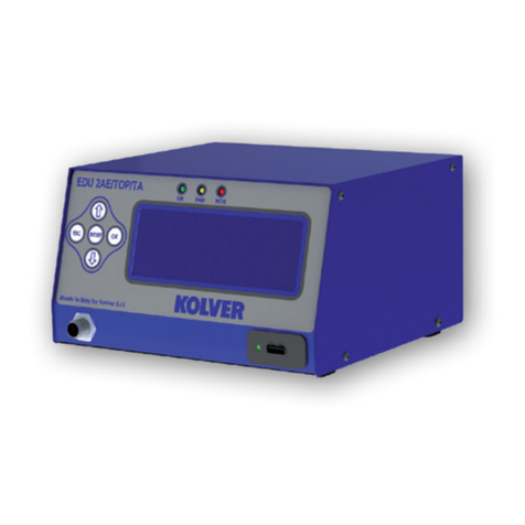
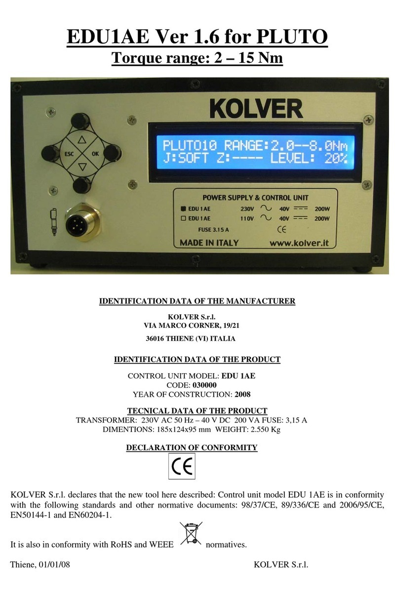
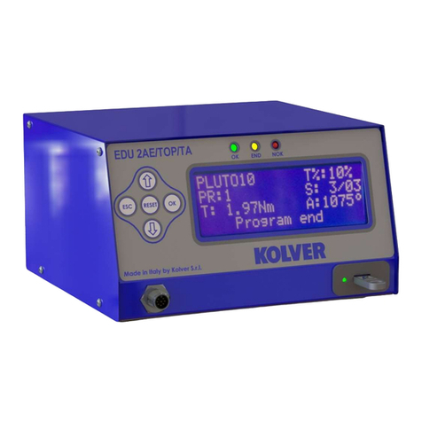
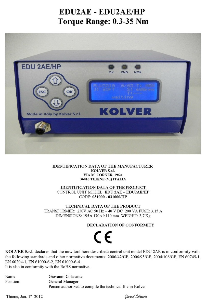
EDU 2AE/TOP power supply and control units are an innovative system for controlling the torque of any
current control MITO and PLUTO electric screwdrivers: MITO15, PLUTO 3, PLUTO 6, PLUTO 10,
PLUTO 15, PLUTO 20, PLUTO 30, PLUTO45, PLUTO50 and PLUTO70, either inline, pistol, push to
start, for automation and with angle head (only PLUTO). It’s also possible to use the following clutch
models: PLUTO 3FR/HS, PLUTO 5FR and PLUTO 7FR.
EDU 2AE/TOP delivers all the advantages of precision torque control electric tools at a fraction of the price
of transdurized tools.
The state-of-the-art electronic control circuit cuts the power supply to the motor calculating the correct
torque in response to 3 parameters; voltage, frequency and current, according to the selected options.
The AC 90÷260V - 50÷60Hz power supply is converted into 40VDC required by the PLUTO series
screwdrivers through a switching board.
Model
Torque
(Nm)
Speed (rpm)
Min
Max
MITO15
0,2-1,5
450
850
PLUTO 3
0,5-3
370
1300
PLUTO 6
0,85-6
200
850
PLUTO 10
1,5-10
110
600
PLUTO 15
2-15
60
320
PLUTO 20
3-20
50
200
PLUTO 35
3-35
40
140
PLUTO 50
5-50
20
90
PLUTO 6 ANG
0,7-6
200
850
PLUTO 8 ANG
1,5 - 7
110
600
PLUTO 15 ANG
2-15
100
320
PLUTO 20 ANG
3-18
60
200
PLUTO 30 ANG
6-30
30
130
PLUTO 45 ANG
10-45
25
90
PLUTO 70 ANG
15-70
25
50
PLUTO 3FR/HS
0,5-2,5
1550
2400
PLUTO 5FR
0,7-5
600
1000
PLUTO 7FR
1,5-7
350
600
IMPORTANT: EDU 2AE/TOP is a highly accurate unit but it is critically important to select the
correct options to ensure that proper torque is being applied. Read the menu description carefully and
in case you are unsure please contact Kolver for support information.
Turn the unit on through the on/off switch on the back panel. The unit will carry a general system check and
the words “waiting connection” will appear on the last line of the display. If the connection with the motor
control board is successful the following screen will be displayed:
K
o
l
v
e
r
S
.
r
.
l
.
E
D
U
2
A
E
/
T
O
P
/
T
A
V
e
r
s
i
o
n
5
.
0
0
l
o
a
d
i
n
g
.
.
.

Vers. 111219 Page 3
P
L
U
T
O
1
0
T
%
:
1
0
%
P
R
:
1
S
:
0
/
0
1
T
:
A
:
r
e
a
d
y
1- Reached torque level in Nm, lbf.in or kgf.cm
2- Program number or sequence
3- Screwdriver model
4- Torque level in percentage
5- Screw count: done screws/total screws
6- Angle value in degrees (only EDU 2AE-TOP TA model)
7- Status bar (ready, errors, etc…)
FRONT PANEL KEYBOARD
To enter the menu press the ESC key for 2 seconds.
Select the line by pressing or then press OK (the symbol
will turn into ). Press the or to select the required
value and then confirm through OK (or ESC if you don’t want
to save the value).
The selected values will be immediately operational, even if you
are still in the menu screen. Repeat the sequence for all the
parameters you wish to change and then push ESC to return to
the main screen.
Press RESET for 3 sec should you need to reset the screw, the
program or the sequence. If you want to see all the set
parameters press for 2 seconds, however you cannot modify
the displayed parameters on this screen.
LEDS ON FRON PANEL
GREEN LED VERDE: indication of Screw OK.
YELLOW LED: indication of Programm End or Sequence End.
RED LED: any indication of error.
2
3
4
5
7
1
6

Vers. 111219 Page 4
MAIN MENU:
-
-
-
-
-
M
A
I
N
-
M
E
N
U
-
-
-
-
-
-
O
K
c
h
a
n
g
e
E
S
C
q
u
i
t
P
r
o
g
r
a
m
s
e
t
t
i
n
g
S
e
q
u
e
n
c
e
s
e
t
t
i
n
g
Program setting:It indicates the menu section where you can set or modify the fastening parameters.
IMPORTANT: To work with switch box, socket tray and remote it is mandatory to go to Sequence
Menu (Ext Box: ON).
Sequence: It indicates the menu section where you can activate the sequence, the switchbox/socket tray
and the bar code.
-
-
-
-
-
M
A
I
N
-
M
E
N
U
-
-
-
-
-
-
S
e
q
u
e
n
c
e
s
e
t
t
i
n
g
U
n
i
t
o
p
t
i
o
n
s
U
S
B
o
p
t
i
o
n
s
Unit Options: It indicates the menu section where you can set date and time, the password and the
language.
AVAILABLE ONLY ON EDU2AE/TOP/E and EDU 2AE/TOP/TA (from 3.0 version on)
USB Options: It indicates the menu section where you can view, upload and create programs setting
of the control unit.
PROGRAM MENU:
The first 28 menu lines are available in both the EDU 2AE/TOP, EDU 2AE/TOP/E and EDU 2AE/TOP/TA
models.
Lines from 29 to 32 are only available in the TOP/TAmodel.
-
-
-
-
-
M
E
N
U
-
-
P
R
:
1
-
-
-
-
-
O
K
c
h
a
n
g
e
E
S
C
q
u
i
t
1
)
P
r
o
g
r
a
m
n
u
m
b
e
r
:
1
2
)
S
c
r
e
w
s
n
u
m
b
e
r
:
1
1) Program number: you can select/ modify the desired program from 1 to 8.
2) Screws number: The EDU2AE/TOP can act as screw counter. You can set the number of screws from
1 to 99. To disable the function press until you get to OFF.

Vers. 111219 Page 5
If the number of correct screws matches to the number of set screws, “PROGRAM END” will appear on the
status bar and the yellow led will light up. If the “Press OK”is ON (see point 18), “PROGRAM END” will
automatically disappear at next screwing or any time you enter the menu. Otherwise, press OK at the end of
each program.
ATTENTION: Every time you enter the menu, the number of screws will reset.
-
-
-
-
-
M
E
N
U
-
-
P
R
:
1
-
-
-
-
-
3
)
M
o
d
e
l
:
P
L
U
T
O
1
0
4
)
R
a
m
p
:
0
.
3
s
5
)
T
o
r
q
u
e
:
1
0
%
1
3) Model: you can select the screwdriver to be used. Your choice will automatically change the default
settings. It’s important to select the correct model you’re going to use since most parameters regarding the
motor software are specific to every single model.
ATTENTION: The pre-set torque level in % and in Nm for PLUTO3FR, PLUTO5FR o PLUTO7FR models
does not appear on the display. Moreover, some settings will be unchangeable, so if you try to modify such
settings it will be displayed: “not available for clutch”.
IMPORTANT: To work with CA drivers, switch box, socket tray and remote it is mandatory to select
ON on Ext. Box in Sequence Menu.
4) Ramp:You can select the slow start time (acceleration) from 0.2 to 3.0 sec. This option is only available
for the screwing phase, while during the unscrewing phase the ramp time is always 0.2 sec. We suggest
using this option with self tapping screws.
ATTENTION: Reaching the torque while the ramp is still on could give as result a different torque level
from the one that results when the ramp is over. This is due to the motor acceleration.
Reaching the torque while the ramp is still on will activate the “screw OK” signal anyway (this option is
useful if you need to tighten screws that are already tightened, the so called “double hit” ).
On the other hand, if you wish to see an error signal during the preset torque in the ramp phase, you can
change the minimum time by setting value which is equal or superior to the ramp value (see point 7).
5) Torque: you can select the desired torque as a percentage of the torque range of the selected
screwdriver. For example, for a Pluto10, a 50% setting will result in a torque in the area of 4 -5 Nm. The
torque range is always referred to the MAX speed. In case you’re not working at maximum speed, the
torque range will progressively lower in order to avoid motor stalling. If the torque level is reached
correctly, it will be displayed and you will hear a beep sound, too.
Such torque level is indicated as “ T: ..% ” on the main screen.
6) Tm Fast Spd (Time Fast Speed): It indicates how long the screwdriver should turn at the FAST
SPEED (see point 7) before switching to the Final Speed.
This Fast Speed Time can be set from 0.3 to 10.0 sec.
To disable the function press until you get to OFF. In this case the screwdriver will automatically start at
pre-set speed (see point 8).
CAUTION: The aim of the FAST SPEED is only to speed up the approach time in case of long screws.
Reaching the torque at higher speed will result in inaccurate torque output. To avoid inaccurate torque
values we suggest first to set a shorter time, and then increase it.
Torque reached during the FAST SPEED won’t activate the torque signal and the message “Error FAST
SPEED” will be displayed on the main screen and 2 beep sounds. The red led will turn on, too.

Vers. 111219 Page 6
-
-
-
-
-
M
E
N
U
-
-
P
R
:
1
-
-
-
-
-
6
)
T
m
F
a
s
t
s
p
d
:
0
.
3
s
7
)
F
a
s
t
s
p
d
:
o
f
f
8
)
F
i
n
a
l
s
p
d
:
6
0
0
r
p
m
7) Fast spd (Fast Speed): You can select the speed of the screwdriver during the FAST SPEED. It can be
set between max speed and the Final Speed (see point 8).
This function is available only if the Fast Speed Time is ON.
8) Final Spd (Final Speed):You can select any speed value of the screwdriver between nominal
(maximum speed given in the catalogue) and the minimum speed of every single screwdriver (see table with
technical data).
-
-
-
-
-
M
E
N
U
-
-
P
R
:
1
-
-
-
-
-
9
)
R
u
n
t
i
m
e
:
2
0
.
0
s
1
0
)
M
i
n
t
i
m
e
:
o
f
f
F
1
1
)
M
a
x
t
i
m
e
:
2
0
.
0
s
9) Runtime:You can set the time of a tightening, from OFF to 20.0 sec. When the pre-set time has been
reached, it results in a torque signal.
The couple reached during this time results in a signal of Correct screw. If the correct screw signal is not
required, set the Minimum time up to a value of 'Minimum Time -0.1sec'.
ATTENTION: Max Time must be set at 20.0 sec.
10) Min time - Minimum Time:You can select the minimum time of screwing from 0.1 sec to 'Max
time - 0.1s'. To disable the function press until you get to OFF (Min time = 0).
Torque reached below the minimum time won’t activate the torque signal and will result in an error
signal. “Below minimum time” will be displayed on the status bar and the red led will light up. You will
hear two beep sounds, too.
11) Max time - Maximum time:You can select the maximum time of screwing. You can set from 'Min
time + 0,1s' to 20.0 sec.
You also can set the Maximum time to OFF by pressing the button when you have reached the value of
20.0s. In this case the screwdriver turns without any time limit.
ATTENTION: If torque isn’t reached by the maximum time, the screwdriver will stop. “Over maximum
time” will be displayed on the status bar and the red led will light up. You will hear two beep sounds, too.
12) Pre-Rev.: pre-reverse. You can unscrew before tightening. This time can be set from OFF to 20.0 sec.
N.B. The speed and torque will be the same as those for the Auto Reverse.
-
-
-
-
-
M
E
N
U
-
-
P
R
:
1
-
-
-
-
-
1
2
)
P
r
e
R
e
v
:
o
f
f
1
3
)
A
u
t
o
R
e
v
:
2
0
.
0
s
1
4
)
R
e
v
s
p
d
:
6
0
0
r
p
m

Vers. 111219 Page 7
13) Auto rev. –Auto reverse: This option will automatically start a reverse after a torque reached signal.
You can set time from 0.1 to 20.0 sec.
To disable the function press until you get to OFF.
ATTENTION: During the reverse, it is necessary to keep the lever or the start signal pressed as long as it
doesn’t stop. “Correct screw” will be displayed on the status bar and a green led will light up. You will
hear one beep sound, too. In case the lever is released before the end of the reverse, “unfinished screw”
will be displayed and a red led will light up. You will hear two beep sounds, too.
14) Rev spd - Reverse speed: You can select any reverse speed value of the screwdriver between the
maximum and the minimum specific speed of every single screwdriver (see table with technical data).
15) Rev torque –Reverse torque: You can select the desired reverse torque as a percentage of the
torque range of the selected screwdriver (see point 2). If the torque is set on MAX, the reverse torque is
about 20% higher than the possible maximum torque, so that it is always possible to unscrew a tightened
screw (we suggest leaving this function on in normal use). If the setting is from MIN to 99% the reverse
torque with the same percentage will be equal to the settings of the screwing phase.
ATTENTION: If you’re using open-end wrenches, the reverse torque has to be set to MIN value in
order to bring the wrench back to the correct position.
16) PV torque: Period of time in which the screwdriver works at maximum torque before switching to
the torque that has been set by the user. You can set time from 0.1 to 10.0 sec.
To disable the function press until you get to OFF.
This function overlaps other time settings (Fast Speed, ramp time, minimum time, maximum time) from the
motor start on.
ATTENTION: This function is useful for applications where the prevailing torque is higher than the final
torque (for example trilobal screws or locknuts).
Please use this function with utmost attention because an incorrect use can damage both the assembly
and the screwdriver.
Torques reached during the max torque time won’t activate the torque signal. “Error pvt time” will be
displayed and the red led will light up. You will hear two beep sounds, too.
17) Rotation: You can choose between right tightening (standard screws) or left tightening (left threaded
screws). All the other functions will adapt to the selected direction of rotation.
18) Press OK: when ON, press OK at the end of each screwing.
When OFF, the control unit resets automatically after a screwing.
19) Press ESC: when ON, press ESC to reset the control unit.
-
-
-
-
-
M
E
N
U
-
-
P
R
:
1
-
-
-
-
-
1
5
)
R
e
v
t
o
r
q
u
e
:
M
A
X
1
6
)
P
V
t
o
r
q
u
e
:
o
f
f
1
7
)
R
o
t
a
t
i
o
n
:
r
i
g
h
t
-
-
-
-
-
M
E
N
U
-
-
P
R
:
1
-
-
-
-
-
1
8
)
P
r
e
s
s
O
K
:
o
f
f
1
9
)
P
r
e
s
s
E
S
C
:
o
f
f
2
0
)
R
e
s
e
t
:
o
n

Vers. 111219 Page 8
When OFF, the control unit resets automatically after an error signal
20) Reset: you can reset the program or the single screw.
-
-
-
-
-
M
E
N
U
-
-
P
R
:
1
-
-
-
-
-
2
1
)
E
r
r
o
r
l
e
v
e
r
:
o
n
2
2
)
D
e
f
i
x
a
l
l
o
w
:
o
f
f
2
3
)
C
a
l
i
b
r
a
t
i
o
n
:
o
f
f
21) Error lever: when ON, an error signal will occur when the lever has released before reaching the
torque.
When OFF, this function doesn’t work.
22) Defix allow: when OFF, the reverse is NOT enabled.
23) Calibration: When ON, you will see the torque value (Nm or in.lbs) on the main screen.
When OFF, the torque value won’t be displayed.
(To modify the calibration parameters see paragraph Torque calibration).
-
-
-
-
-
M
E
N
U
-
-
P
R
:
1
-
-
-
-
-
2
4
)
C
o
m
p
e
n
s
:
0
.
0
0
N
m
2
5
)
T
o
r
q
m
i
n
:
0
.
0
0
N
m
2
6
)
T
o
r
q
m
a
x
:
2
0
.
0
0
N
m
24) Compens –Compensation: This function allows an increase or decrease of the displayed torque
value after a calibration. The available range is from 0 to ±55 Nm. For example: after calibration (see
Torque calibration) you make a screwing on your assembly and compare the displayed value to the value
you see on a torque tester (for example a mini-K or a K model). Let's say you notice that the torque
displayed in the unit EDU 2AE/TOP is +0.2 Nm higher than the value indicated on the tester (which is the
right one). In this case you can modify this value by setting -0.2 Nm so that the value on the display will be
the same as the value on the tester. If it’s lower than 0.3 Nm, you need to set +0.3 Nm and so on.
25) Torq min –Minimum torque: The minimum torque and maximum torque options allow the user to
set the acceptable torque range for each single application. When the reached torque is within this range,
“Screw OK” will be displayed on the status bar and the green led will light up. If the reached torque is
outside this range, “error minimum torque” or “error maximum torque” will be displayed and the red led
will light up. You can set the torque range from 0 to ‘Torq Max-0.01 Nm’ in steps of 0.01 Nm.
The minimum torque option allows to set the lowest value of the torque range. When Calibration is OFF, the
minimum torque value automatically sets on 0 Nm.
The selection of the torque value is carried out by entering the digit cell by cell.
26) Torq max –Maximum Torque: The minimum torque and maximum torque options allow the user
to set the acceptable torque range for the single application. When the reached torque is within this range,
“Screw OK” will be displayed on the status bar and the green led will light up. If the reached torque is
outside this range, “error minimum torque” or “error maximum torque” will be displayed. You can set the
torque range from ‘Torq Min+0.01 Nm’ to 55 Nm at intervals of 0.01 Nm.
The maximum torque option allows to set the highest value of the torque range. When Calibration is OFF
the maximum torque value automatically sets on 55 Nm.

Vers. 111219 Page 9
The selection of the torque value is carried out by entering the digit cell by cell.
-
-
-
-
-
M
E
N
U
-
-
P
R
:
1
-
-
-
-
-
2
7
)
I
n
s
.
b
a
r
c
o
d
e
2
8
)
S
e
r
i
a
l
P
R
T
:
o
f
f
2
9
)
F
u
n
c
T
&
A
:
o
f
f
27) Ins. barcode: to scan a barcode and recall the desired program. To be used in combination with option
4. of the Sequence Menu.
IMPORTANT: Barcode can be ONLY numeric.
28) Serial PRT: Serial print: from OFF to 5.
When OFF, no print.
If it is set up to 5, this value identifies the number of line feeds between a string and another.
THE FOLLOWING MENU IS AVAILABLE ON T&AVERSION ONLY
-
-
-
-
-
M
E
N
U
-
-
P
R
:
1
-
-
-
-
-
2
9
)
F
u
n
c
T
&
A
:
o
f
f
3
0
)
S
t
a
r
t
i
n
g
T
o
r
:
-
-
-
3
1
)
A
n
g
.
m
i
n
:
-
-
-
-
29) Func T&A–T&A function mode: You can activate the Torque & Angle function. Set OFF when
you don’t need this function. When you set ON you can choose among six working conditions (see T&A
specific instructions).
30) Starting Tor –Starting torque: If T&A option is set on Tor mode (See T&A paragraph), you can
set the torque threshold the angle starts to be read from. When T&A is set on angle mode (see T&A
paragraph), you can set the torque threshold the angle starts to be carried out from.
31) Ang. min –Minimum angle: Minimum angle threshold. You can set it when T&A is set on Tor, T/in
or T/lv (see T&A specific instructions). The minimum angle the operator can set is 5°.
-
-
-
-
-
M
E
N
U
-
-
P
R
:
1
-
-
-
-
-
3
1
)
A
n
g
.
m
i
n
:
-
-
-
-
3
2
)
A
n
g
.
m
a
x
:
-
-
-
-
32) Ang. max - Maximum angle: Maximum angle threshold. You can set it when T&A is set on Tor,
T/in or T/lv (see T&Aspecific instructions). The maximum angle the operator can set is 29999°.
When T&A is set on Ang., A/in or A/lv mode, maximum angle corresponds to the angle that has to be
carried out.

Vers. 111219 Page 10
SEQUENCE MENU:
-
-
-
S
E
Q
U
E
N
C
E
-
M
E
N
U
-
-
-
-
O
K
c
h
a
n
g
e
E
S
C
q
u
i
t
1
)
S
e
q
s
e
t
:
1
4
7
3
9
8
1
2
2
)
S
e
q
u
e
n
c
e
:
o
f
f
1) Seq set: you can set a sequence up to max. 8 programs.
To set the next program in the sequence, press OK.
Press to save the sequence and quit.
2) Sequence: to enable or disable the sequence. ON = enabled; OFF = disabled.
-
-
-
S
E
Q
U
E
N
C
E
-
M
E
N
U
-
-
-
-
3
)
E
x
t
b
o
x
:
o
f
f
4
)
M
o
d
.
b
a
r
c
:
o
f
f
5
)
I
n
s
.
b
a
r
c
o
d
e
S
e
q
3) Ext box: It allows to enable or disable the external control.
IMPORTANT: It is mandatory to select ON to work with switch box, socket tray and remote.
4) Barc. mode: –Barcode mode: It allows to choose the barcode mode.
OFF: barcode disabled.
ON prog: you can select the program to be executed by scanning the bar code of the product. The
unit compares the scanned code to the one previously entered in each program (see point 27: Barc.
Set.). If the two codes match, the program is loaded; otherwise it will display Error Barcode. The
scanned product code is also printed on the serial port of the control unit (see paragraph “serial
print”).
ON S.N.: the product code is required before running a program or a sequence. The product code is
printed on the serial port of the control unit.
ON Seq.: you can set the Sequence by scanning its barcode. The code scanned is compared with
the sequence entered in the menu (see point 5: Ins. Barcode Seq on Menu Sequence). If the
two codes match, the sequence set is loaded, otherwise display “Repeat scan”. The read
code is also printed on the serial port of the control unit (see section Serial Print).
5) Ins. Barcode Seq: When ON on “Barc. Mode → ON Seq.”, you have to scan the barcode to enable the
Sequence.
IMPORTANT: Barcode can be ONLY numeric.
-
-
-
S
E
Q
U
E
N
C
E
-
M
E
N
U
-
-
-
-
6
)
R
e
s
e
t
S
e
q
.
:
o
f
f

Vers. 111219 Page 11
7
)
R
e
s
.
s
e
q
a
u
t
:
o
n
6) Reset seq.: When ON, you can reset the Sequence (pushing the Reset button).
7) Aut. res seq- Automatic Reset Sequence: When ON, the control unit automatically resets after the
end of the sequence. When OFF it is necessary to press OK at the end of each sequence.
OPTION MENU:
-
-
-
-
-
M
A
I
N
-
M
E
N
U
-
-
-
-
-
-
S
e
q
u
e
n
c
e
s
e
t
t
i
n
g
U
n
i
t
o
p
t
i
o
n
s
U
S
B
o
p
t
i
o
n
s
Unit Options:
-
-
-
-
O
P
T
I
O
N
S
-
M
E
N
U
-
-
-
-
O
K
c
h
a
n
g
e
E
S
C
q
u
i
t
1
)
L
a
n
g
u
a
g
e
:
E
N
2
)
C
h
a
n
g
e
p
a
s
s
w
o
r
d
1) Language: This option allows to choose among the languages available: English, French, German,
Italian, Spanish and Portuguese.
2) Change password: You can change password (see point 3).
-
-
-
-
O
P
T
I
O
N
-
-
M
E
N
U
-
-
-
-
3
)
P
a
s
s
w
o
r
d
:
o
n
4
)
E
S
C
-
O
K
-
R
S
T
:
e
x
t
5
)
U
n
i
t
:
N
m
3) Password ON: When YES, you will be asked for the password to enter the menu. Otherwise select NO.
ATTENTION: Password is only asked to enter the menu the first time after switching the unit on.
The default password is: 0000.
4) ESC-OK-RST: Press ESC in case of error. Press OK at the end of a program or to reset a sequence or a
program (see point 7: Reset).
When INT, the operator must press the required key on the front panel.
When EXT, functions can only be enabled through proper connections on the back panel (see paragraph I/O
connections).
When INT+EXT you can press either he button on the front or on the back panel.
5) Unit: You can choose between the following units of measurements: Nm, lbf.in and kgf.cm

Vers. 111219 Page 12
-
-
-
-
O
P
T
I
O
N
S
-
M
E
N
U
-
-
-
-
6
)
V
e
r
s
i
o
n
s
7
)
S
e
r
i
a
l
n
.
0
0
0
0
0
0
0
0
8
)
S
e
t
t
i
m
e
&
d
a
t
e
6) Versions: in this screen you can see the versions of boards mounted inside the unit.
7) Serial number: it is the indication number of the control unit. Default number: 0000000.
It could be the real serial number of the unit or another one you could choose (7 digits max).
This number will also be the name of the folder in the USB drive where you will save the report of
your data (see EDU EXPAND part).
-
-
-
-
O
P
T
I
O
N
S
-
M
E
N
U
-
-
-
-
7
)
S
e
r
i
a
l
n
.
0
0
0
0
0
0
0
0
8
)
S
e
t
t
i
m
e
&
d
a
t
e
9
)
C
y
c
l
e
s
:
0
0
0
0
0
0
0
8) Set time & date: to set time and date on the control unit.
9) Cycles - Total number of cycles: It shows the number of tightened and loosened screws. This number
can’t be modified.
USB Options:
-
-
-
-
O
P
T
I
O
N
S
-
M
E
N
U
-
-
-
-
1
)
R
e
a
d
U
S
B
2
)
W
r
i
t
e
U
S
B
3
)
I
n
f
o
U
S
B
1) Read USB: press OK and read the USB drive and select the file SETxx.KOL you desire.
The EDU control unit recognizes only files as SETxx.KOL (see EDU EXPAND part).
S
e
l
e
c
t
P
r
o
g
r
a
m
S
E
T
0
0
.
K
O
L

Vers. 111219 Page 13
O
K
c
o
n
f
i
r
m
E
S
C
q
u
i
t
2) Write USB: press OK and create your new SETxx.KOL application where you save all the
parameters you have set in the control unit.
S
a
v
e
a
s
S
E
T
0
0
.
K
O
L
O
K
c
o
n
f
i
r
m
E
S
C
q
u
i
t
3) Info USB: press OK and see the loaded program.
You can see the loaded program only if you have saved the program in your USB drive as named as
SETxx.KOL.
L
o
a
d
e
d
p
r
o
g
r
a
m
:
S
E
T
2
3
.
K
O
L
TORQUE CALIBRATION
The torque calibration function allows to view the torque value in Nm or in.lbs or kgf.cm directly on the
display of the control unit.
IMPORTANT: You need a torque tester to proceed, either with static transducer (model minik or K)
or with rotary transducer (model minik-e).
CALIBRATION PROCESS:
1. Select Calibration at point 23 of the menu and press OK.
2. The following screen will appear on the display:
-
-
-
-
-
-
-
-
M
E
N
U
-
-
-
-
-
-
-
-
2
3
)
C
a
l
i
b
r
a
t
i
o
n
o
n
3. Press OK to confirm. If you choose OFF, calibration will be interrupted and no torque value will be
displayed. You choose ON, calibration will continue and the following screen will be displayed:
-
-
-
-
-
-
-
-
S
T
E
P
-
-
1
-
-
-
-
-

Vers. 111219 Page 14
4. Set the first torque level at 20% percentage by pressing .
(20% is just an example).
5. Press OK. You will see:
-
-
-
-
-
-
-
-
S
T
E
P
-
-
1
-
-
-
-
-
S
t
a
r
t
t
e
s
t
O
K
c
o
n
f
i
r
m
E
S
C
q
u
i
t
Complete a screwing cycle on the mini k5 and take note of torque value.
In case of error, you will see:
-
-
-
-
-
-
-
-
S
T
E
P
-
-
1
-
-
-
-
-
S
t
a
r
t
t
e
s
t
E
r
r
.
R
e
p
e
a
t
S
c
r
e
w
i
n
g
Just repeat the test.
6. Press ESC to abort the calibration process.
Press OK, then the display will show:
-
-
-
-
-
-
-
-
S
T
E
P
-
-
1
-
-
-
-
-
E
n
t
e
r
t
o
r
q
u
e
v
a
l
u
e
:
0
0
.
0
1
N
m
Set the torque value by selecting each digit individually pressing and and press OK to confirm it, then
press OK again to save. You will see:
E
n
t
e
r
t
h
e
p
e
r
c
e
n
t
a
g
e
M
I
N
-
-
-
-
-
-
-
-
S
T
E
P
-
-
2
-
-
-
-
-
E
n
t
e
r
t
h
e
p
e
r
c
e
n
t
a
g
e
2
0
%

Vers. 111219 Page 15
-
-
-
-
-
-
-
-
S
T
E
P
-
-
2
-
-
-
-
-
E
n
t
e
r
t
h
e
p
e
r
c
e
n
t
a
g
e
:
2
5
%
7. Set the percentage of the second torque to 25% by pressing and press OK.
(25% is just an example).
8. Repeat the procedures described on points 4 and 5.
9. When calibration ends, “Setting end” will be displayed. You will hear two beep sounds, too.
Now you are ready to work and see the correct torque on the display.
WARNING:
- Calibration values will be referred to the parameters of the control unit which are set during
calibration, i.e. if you modify speed or torque, the unit will need to be recalibrated. During
calibration when a screwing is not carried out correctly or if for any reasons you’re not sure of the
torque value it is possible to repeat it. A wrong screwing can affect the precision of the calibration.
- Calibration is carried out for two torque levels optionally chosen. The minimum calibration interval
is 5% (example: if I have to work at 50%, I can calibrate at 45% and 55%). In this case, if for any
reasons I need to work at torque percentages which are lower or higher than the min-max ones set
during the calibration, they will be analyzed and displayed anyway but since they won’t be based on
effective data the torque value displayed may be not accurate.
- During calibration it is not possible to go back to the previous screen. Press ESC to stop calibration
and then repeat the screwing cycles.
USE OF T&A (Torque & Angle)
Choose the T & A mode (see point 29: Modify function on the program menu)
It is possible to set 6 different modes:
TORQUE (Torque): It’s the most common use mode. The control unit shows the tightening torque and
the torque starting from a certain torque percentage (threshold torque, see point 30). If the final torque
and angle values are within the preset minimum and maximum values, the screw is correctly tightened.
If the torque and/or angle are outside the preset values, the screw will be considered as incorrectly
tightened. In this case the red led will light up and the message “Error Max (Min) Angle” or “Error Max
(Min) Torque”will be displayed.

Vers. 111219 Page 16
TORQUE/INPUT (T/IN): It corresponds to Torque mode, except for the threshold torque which
can’t be set by the operator: in fact the value is the result of an external impulse through a proper
contact (see paragraph “connections”). It can be very useful if the operator wants the control unit to
start counting the angle from a position which is indicated by a precision instrument.
TORQUE/LEVER (T/LV): No threshold is preset by the operator: the angle value that appears on
the display corresponds to the angle that is carried out starting from the moment in which the lever
is pressed until the torque is reached.
ANGLE (Ang.): This mode gives priority to the angle to be reached. The value is measured starting
from a tightening torque percentage.
Starting from the preset threshold torque (see point 30) the system will start counting the degrees
and when the preset angle is reached the screwdriver will stop. If the preset angle is reached the
screw will be considered as correctly tightened, the green led will light up and the message
“tightening OK” will be displayed on the status bar. If the screwdriver stops before reaching the
preset angle the tightening will be considered not ok, the red led will light up and the message “error
angle not reached” will be displayed on the status bar. Therefore it’s very important to set a torque
value (line 5) which is sufficiently higher than the threshold value (line 30), so that the set value is
reached before the screwdriver stops because of the reached torque.

Vers. 111219 Page 17
ANGLE/INPUT (A/IN): The threshold can’t be set by the operator: in fact the value is the result of
an external impulse through a proper contact (see paragraph “connections”).
This function can be very useful if the operator wants the screw to rotate a certain number of
degrees after reaching a position indicated by a precision instrument.
ANGLE/LEVER (A/LV): the threshold torque value can’t be set by the operator and the angle value
that appears on the display corresponds to the angle that is carried out starting from the moment in
which the lever is pressed.
INTERPRETATION OF ACOUSTIC SIGNALS
The control unit emits sounds which help you understand if the screwing has been carried out correctly or
not. When the torque is reached meeting all the parameters set, the control unit utters a 0.5 sec beep as
confirmation. In case of Program End, the unit will utter other two beeps. On the other hand, torque reached
under min time, during the Ramp time or under the Fast Speed (see error signals on the display) will cause
the control unit to utter three beep sounds.

Vers. 111219 Page 18
I/O CONNECTIONS:

Vers. 111219 Page 19
CN1 CONNECTOR –10 pins
It is situated on the upper part of the back panel.
PIN
NAME
FUNCTION
OUTPUT
1
+24V
+24V voltage protected. The maximum current consumption is 400mA. CAN NOT BE
USED TO POWER EXTERNAL DEVICES.
2
GND
Common pin. Signals must be taken between this pin (GND and the respective signal pins
(pin 3, 4 and 5).
3
ERROR
Error signal: it activates every time an error occurs.
The red led on the front panel will switch on.
Signal is 24V.
4
MOTOR ON
(\W)
It activates when the motor turns during screwing. Signal is 24V.
5
SCREW OK
Correct screw signal. The green led on the front panel will switch on.
Signal is 24V.
INPUT
6
T&A INPUT
External input for making the control unit start to count the angle. It can be only used in
A/IN and T/IN mode (see T&A paragraph)
7
STOP
MOTOR
Remote motor stop. If it’s activated the message “STOP MOTOR ON” appears on the
display. The motor will stop and won’t start working again as long as the contact is closed
(as Input pin 1 of CN2).
8
REVERSE
Remote motor start with torque control while unscrewing.
9
START
Remote start with torque control while screwing.
10
GND
Common pin. The desired function is activated through a contact between this pin and
one of the other pins.

Vers. 111219 Page 20
CN2 CONNECTOR –14 pins
All of the following pins are input: make a contact with pin 14 to activate them.
PIN
NAME
FUNCTION
1
STOP MOTOR
Remote motor stop. If it’s activated the message “STOP MOTOR ON”
appears on the display. The motor will stop and won’t start working again as
long as the contact is closed (as Input pin 1 of CN2).
2
MISSING PIECE
If enabled it stops the motor, enables the error signal and “Error missing
piece”is displayed on the status bar.
3
OK EXT
If enabled (see point 4: OK-ESC commands, in the option menu), remote
OK key function.
4
ESC EXT
If enabled (see point 4: OK-ESC, in the option menu), ESC key function to
reser remote errors.
5
RESET EXT
If enabled (see point 4: OK-ESC commands, in the option menu), it resets
program or sequence according to the preset function (see point 5: Reset, in
the option menu)
6
INPUT 8
Switch –selection of program 8
7
INPUT 7
Switch –selection of program 7
8
INPUT 6
Switch –selection of program 6
9
INPUT 5
Switch –selection of program 5
10
INPUT 4
Switch –selection of program 4
11
INPUT 3
Switch –selection of program 3
12
INPUT 2
Switch –selection of program 2
13
INPUT 1
Switch –selection of program 1
14
GND
Common to every input. Signals have to be enabled making contact between
the desired signal and this pin (GND) .
This manual suits for next models
6
Table of contents
Other Kolver Power Supply manuals
Popular Power Supply manuals by other brands

Cross Technologies
Cross Technologies 2000-2 LNB Series instruction manual

Vertiv
Vertiv NetSure 8200 Series user manual

SloanLED
SloanLED 701507-60W2 installation guide

Vector
Vector VEC022 Owner's manual & warranty

Phoenix Contact
Phoenix Contact EV-T2M3SO12-3P-P-SET manual

ABB
ABB CPS6000-Systems-48V DC Power installation manual