Kolver EDU1AE User manual

EDU1AE Ver 1.6 for PLUTO
Torque range: 2 – 15 Nm
IDENTIFICATION DATA OF THE MANUFACTURER
KOLVER S.r.l.
VIA MARCO CORNER, 19/21
36016 THIENE (VI) ITALIA
IDENTIFICATION DATA OF THE PRODUCT
CONTROL UNIT MODEL: EDU 1AE
CODE: 030000
YEAR OF CONSTRUCTION: 2008
TECNICAL DATA OF THE PRODUCT
TRANSFORMER: 230V AC 50 Hz – 40 V DC 200 VA FUSE: 3,15 A
DIMENTIONS: 185x124x95 mm WEIGHT: 2.550 Kg
DECLARATION OF CONFORMITY
KOLVER S.r.l. declares that the new tool here described: Control unit model EDU 1AE is in conformity
with the following standards and other normative documents: 98/37/CE, 89/336/CE and 2006/95/CE,
EN50144-1 and EN60204-1.
It is also in conformity with RoHS and WEEE normatives.
Thiene, 01/01/08 KOLVER S.r.l.

EDU1AE power supply and control unit is an innovative system for controlling the torque
of both our PLUTO10 and PLUTO15 electric screwdrivers either inline, pistol or for
automation.
EDU1AE and Pluto delivers all the advantages of precision torque control electric tools at a
fraction of the price of transdurized tools.
The state-of-the-art electronic control circuit cuts the power supply to the motor calculating
the correct torque in response to 3 parameters; voltage, frequency and current, according to
the selected options.
IMPORTANT: EDU1AE controller is a highly accurate unit but it is critically important to
select the correct options to ensure that proper torque is being applied. Read the menu
description carefully and in case you are unsure please contact Kolver for support
information.
Here are a few advantages of EDU1AE:
•One controller only for a torque range from 2 to 15 Nm. On certain joints torque values
between 0.5 and 2 Nm are also possible. Please contact Kolver for additional information.
•User interface screens: walk through a few simple steps to input the parameters requested
for your application and your fastening process can begin.
•Slow start and adjustable speed.
•Soft or hard joint application.
•High speed rundown and slow speed tightening for improved accuracy.
•Automatic reverse at cycle end possible.
•Autostop on elapsed time.
•Torque reached signal, lever signal.
•Start and reverse contacts.
•Remote torque selection possible (please contact Kolver for additional information).
•Low noise level, only 55 dBA, low weight, less than 0.5 kg .
TORQUE RANGE:
PLUTO10:
•HARD programme: max torque 9,80 Nm
•SOFT programme: max torque 8,10 Nm
•S-E (semi-elastic joint K5 and K20): max torque 8,70 Nm
PLUTO15
•HARD programme: max torque 14,70 Nm
•SOFT programme: max torque 13,50 Nm
•S-E (semi-elastic joint K5 and K20): max torque 14,90 Nm
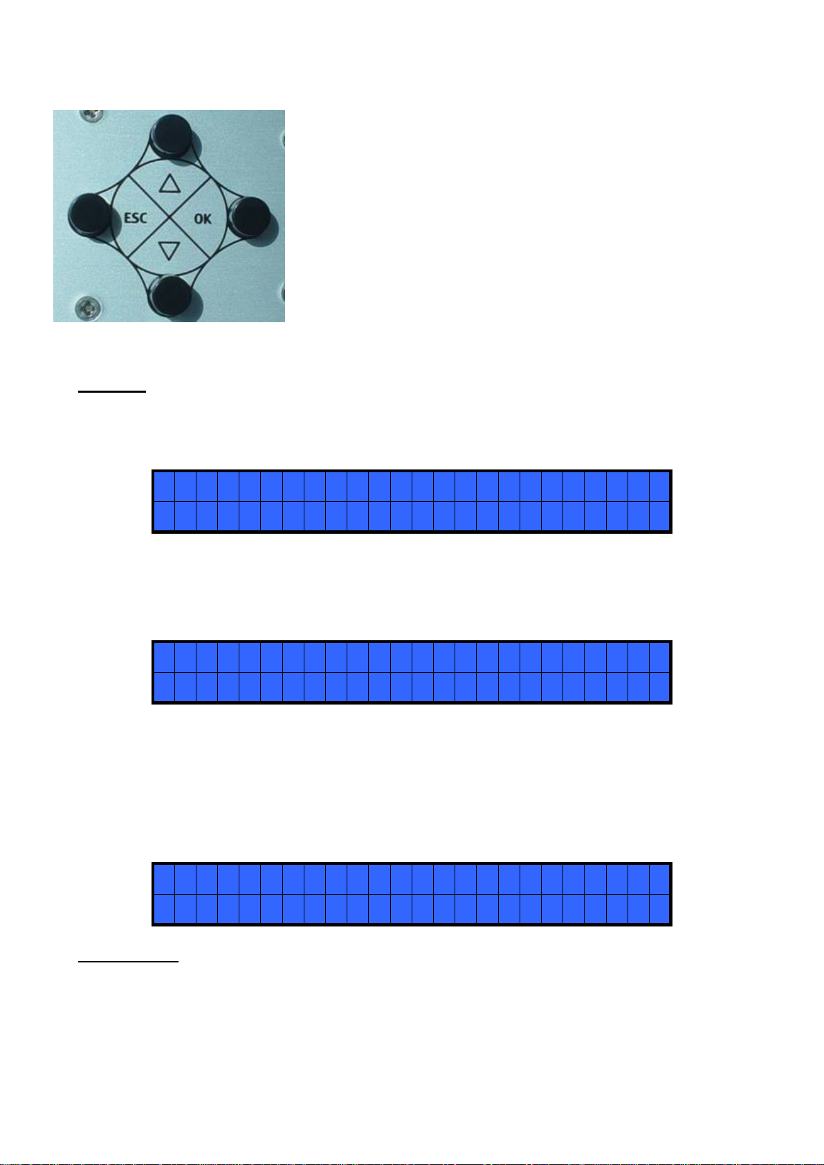
Turn the unit on through the on/off switch on the back panel. The unit will carry a general system
check and then display the main screen indicating the screwdriver model (Pluto10 or 15), the
corresponding torque range (Range: 2-10 or 2-15 Nm), the joint type (J: Hard or J: Soft), the brake
time (Z) and the torque level (Level).
P L UTO1 0 RANGE : 2 . 0 - 1 0 . 0 Nm
J : SOF T Z : - - - - L EVE L : 2 0
%

To enter the menu push the ESC key for 3 seconds
The menu consists of 8 lines. To move through the menu push the
∇or Δkeys. Pusk the OK key to select a line ( the arrow →will
start blinking). Push the ∇or Δkeys to select the required value
and then confirm thru the OK key (or ESC if you don’t want to
save the value). The selected value will be immediately operational
also if you are still in the menu screen. Repeat the sequence for all
the parameters you wish to change and then push the ESC key to
return to the main screen.
MENU
1) MODEL: you can select the screwdriver to be used (Pluto10 or Pluto15). Your choice will
automatically change the default settings.
> 1) MODE L : P L UTO 1 0
2 ) TORQUE L EVE L : M I N
2) TORQUE LEVEL: you can select the desired torque as a percentage of the torque range of the selected
screwdriver. For example, for a Pluto10, a 50% setting on hard joint will result in a torque in the area of
6Nm. Please confirm desired torque value with a Kolver digital torque tester. The torque level is indicated on
the main screen by “LEVEL” .
1) MODE L : P L UTO 1 0
> 2 ) TORQUE L EVE L : M I N
3) JOINT: You can select the type of joint (soft or hard) you are working on. A soft joint is typically a self
tapping screw on plastic or sheet metal, or a metric (machine) screw on a material subject to strain (for
example: gasket, o ring etc) A hard joint is typically a fastener joining metal with metal.
If you select the option SOFT the screwdriver will run the complete cycle at the selected speed (see point 6.).
When selecting the option HARD the screwdriver will maintain the selected speed for a selected time after
the start (see point 4.) and then the speed will be reduced automatically to apply a pre-torque before reaching
the preset torque (see point 2.)
> 3) J O I NT : SOF T
4 ) BRAKE T I ME : OF F
IMPORTANT: An incorrect selection of the joint type can result in unaccurate torque output.

4) BRAKE TIME: This option can be selected only in combination with the option JOINT: HARD.
You can select a time between MIN (function excluded) and 10.0 seconds indicating how long the selected
speed (higher speed) will be on before switching to “pre-torque speed” (lower speed). The “pre-torque
speed” will be automatically chosen by the unit depending on the preset torque. The user cannot adjust the
“pre-torque speed”. This brake time is indicated on the main screen by letter “Z”.
3) J O I NT : SOF T
> 4 ) BRAKE T I ME : 0. 1 5 s
CAUTION: The scope of the time “Z” is only to speed up the approach time in case of long screws.
Reaching the torque at higher speed will result in inaccurate torque output. To avoid inaccurate torque we
suggest selecting a shorter time, and then increase it step by step until finding the optimum time.
Torque reached during the Brake Time will result in lever and error signals and 3 bip sounds.
5) RAMP TIME: You can select the slow start time (acceleration) from 0.2 to 2 seconds. This option is
mainly used with self-tapping screws. Reaching the torque while the ramp is still on will result in inaccurate
torque output.
Torque reached during the Ramp Time will result in lever and error signals and 3 bip sounds.
> 5 ) RAMP T I ME : 0.2 5 s
6 ) SPE ED : 6 0 0 RPM
6) SPEED: You can select any speed value of the screwdriver between nominal (max) speed and 30% of
max speed (see also point 3.)
NB. The torque range is ensured only at the nominal speed of the screwdriver (600 RPM for Pluto10 and 320
RPM for Pluto15). If you should set lower speeds, please check if the screwdriver stops correctly at the pre-
set torque. See also point 4 (Brake Time) for speed in JOINT: HARD.
5 ) RAMP T I ME : 0.2 5 s
> 6 ) SPE ED : 6 0 0 RPM
7) STOP TIME: You can select a time between 0.2 (function excluded) and 10 seconds in case you need to
stop the screwdriver at depth, or time, and not at torque. At the end of the selected time the unit will release a
“time out” signal (torque reached signal). Please note that the torque selected (see point 2) will stay on,
should the screwing cycle be shorter than the stop time.
> 7 ) S TOP T I ME : 1 0 . 0 s
8 ) REVERSE T I ME : OF F
8) REVERSE TIME: This option will automatically start a reverse cycle after a torque reached signal or a
time out signal (see also point 4 and 5). You can select a time between OFF (function excluded) and up to 10
seconds. During the reverse cycle, it is necessary to keep the lever pressed or the start signal otherwise the
screwdriver will stop before the pre-set time.
> 7 ) S TOP T I ME : 1 0 . 0 s
8 ) REVERSE T I ME : OF F

I/O CONNECTION
On the back panel you’ll find only one connector I/O 10 pins which must be connected to the 90°
connector coming from the unit.
INPUT:
PIN FUNCTION
1 COM 0VDC Common pin. By closing the contact between pin 1 and any of the other pins ( 2, 3, 4, 5)
to start the function you need.
2 START Remote start. Clockwise. Torque control.
3 REVERSE Reverse remote start. Counterclockwise. No torque control
4 STOP Stop motor. “STOP ACTIVE”screen. Motor stops and starts again after the contact has
opened.
5 NOT USED Only used in special versions.
OUTPUT:
PIN FUNCTION
6 TORQUE Torque reached signal. Signal is 24V 20 mA , max 0,5W.
7 LEVER Lever signal: when lever is pressed or when the start is remote. No signal during
unscrewing cycle. It resets after their release. Signal is 24V 20 mA , max 0,5W.
9 COM0VDC Common pin for any output. Signals must take between pin 1 ( 0VDC common) and the
other pins (6,7 and 8).
10 NOT USED Only used for special versions.
Output signals are protected. Overload of these 3 available signals (> 60 mA) or short circuit will result
in the stop of the unit. To re-activate signals, it is necessary switch off the unit for 5-6 seconds, check
connections outputs then switch on the unit.
BIP SOUNDS
Bip sounds at the end of the screwing allow to check if the screwing itself is correct or not.
A screwing results correct when the torque has been reached satisfying all the settings (0,5 sec bip
sound). Torque reached during Ramp or Brake Time (only on hard joint) will result 3 bip sounds.
NB. Torque reached during Ramp or Brake Time will result in torque reached signal. For Brake
Time only in error signal also.

TROUBLE SHOOTING
ERROR
# PROBLEM ACTION / SOLUTION
0
N
o connection between main PCB and display PCB Check flat connector inside the unit
1
C
hoosing SOFT joint and working on a HARD joint:
t
he screwdriver will stop - Switch the unit off and on again after 5
seconds and check the joints
2
C
hoosing HARD joint and working on a SOFT joint:
t
he screwdriver will stop - Switch the unit off and on again after 5
seconds and check the joints
5
B
us undervoltage (it happens when the supply +Vbus
t
o the motor remains below 25V for more than 3
seconds)
- Make sure that 110/230 (depending on
Country) VAC input is supplied
6 Overload on bridge H (it happens when current on
m
osfets of bridge H > 10 A for more than 600 ms)
- Reduce cycle rate
- Avoid motor stalling
7
M
otor not detected (it happens when the motor
connection is missing) - Check cable and connection between
screwdriver and controller
8 Overload on bridge H (it happens when current on
m
osfets of bridge H > 14,5 A for more than 10 ms)
- Reduce cycle rate
- Avoid motor stalling
- Unscrewing too heavy (> tool torque
range)
NB. TO RESET ERRORS, TURN OFF THEN SWITCH ON THE UNIT. RESET OF ERRORS #6
AND #8 COMES AUTOMATICALLY AFTER THE PROBLEM END.
IF THE PROBLEM PERSISTS, PLEASE CONTACT YOUR NEAREST KOLVER DEALER.
EDU1AE power supply and control unit is a maintenance free unit. Should you need any assistance please
call the nearest Kolver dealer in your Country or contact directly Kolver at [email protected] or call
+39 0445 371068. In the US call 978-692-2468.

RIF DESCRIPTION CODE RIF DESCRIPTION CODE
1 Connector 5 PIN M12 M 201666 16 Plug w/fuseholder 230V 800618
2 Screw 2,6 x 9,5 (12pcs) 800605 17 Earth cable 800090
3 Nut M2,5 h 11 872436 18 Plug internal cable 800080/N
4 Button for user interface 872437 19 Back panel 832414
5 Rubber support (4pcs) 800016 20 Nut M3 800056
6 Screw M6 x 60 872430 21 Washer M3 800041
7 Alu box 812010/VB 22 Screw M3 x 8 806235
8 Internal connector 872438 23 Nut M6 872433
9 Main PCB 852421
10 Connector I/O 10 pin F 800109 24 Transformer 230/36-18V
200VA w/fixing plate 848009
11 Thickness 800110
25 PCB display 852422/N
14 Fuse 3,15 A 800619 26 Nut M2,5 h 7 872435
15 Power supply cable 800620 27 Front panel 822426
Table of contents
Other Kolver Power Supply manuals