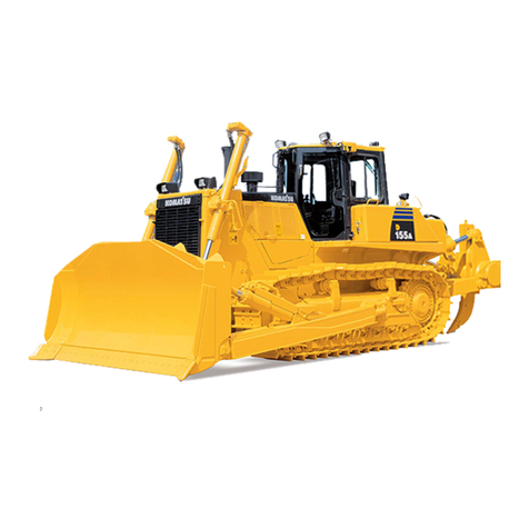
Komatsu D155A-6 User manual

BULLDOZER
Field Assembly Instruction
GEN00078-02
D155A -6
SERIAL NUMBERS 85001 and up

Preface
Preface
Since this machine is large in size, it is divided into some units to meet
the transportation conditions and regulations applied to the transporta-
tion route when shipped from our factory.
This manual describes how to assemble the units into the complete
machine in the field. We hope that this machine will display its quality
and you will use it safely according to the operation manual.
Many units are large in size and heavy in weight and may be handled
in a dangerous place or posture and many workers may have to work
together to sling them with cranes.
Accordingly, before starting the assembly work, the work supervisor is
required to hold a safety meeting to oblige the workers to put on pro-
tective gear and appoint a work leader and a crane work signal man
and allot roles to all the workers for safe work.
In particular, the above meeting is more important when worker of dif-
ferent languages and customs work together.
The following is a reference supervision system diagram.
When the work equipment is installed, the engine must be operated.
Accordingly, before installing the work equipment, inspect and main-
tain the machine thoroughly.
Note that this manual does not describe the whole specification of the
machine but describes only the basic specification.
If you have any question when dividing and transporting the machine
by yourself in future, ask one of our distributors.
(Instruction system)
Work leader
Work supervisor Crane director Director
and
deputy director
Liaison man Operator for assembly
Interpreter Mechanics Sharing of work


CONTENTS
Specifications ..................................................................................................................................................... 1
Precautions for field assembly............................................................................................................................ 3
Assembly procedure, necessary equipment, and schedule ............................................................................... 4
Layout of kit ........................................................................................................................................................ 5
Style for transportation ....................................................................................................................................... 6
List of tools for field assembling ....................................................................................................................... 11
Tightening torque ............................................................................................................................................. 12
Coating materials ............................................................................................................................................. 16
A. Assembly procedure
A-1 Unloading and installing tractor........................................................................................................ 20
A-2 Installing track shoes........................................................................................................................ 21
A-3 Assembly of blade............................................................................................................................ 22
A-4 Installation of blade lift cylinder ........................................................................................................ 28
A-5 Installation of blade .......................................................................................................................... 30
A-6 Installation of ripper assembly.......................................................................................................... 32
A-7 Adjusting track tension ..................................................................................................................... 39
A-8 Check fuel, coolant and lubricants ................................................................................................... 41
A-9 Lubricating........................................................................................................................................ 43
A-10 Bleeding air from hydraulic cylinders ............................................................................................... 46
A-11 Installation of additional working lamps............................................................................................ 47
S. Reference material (Installed when delivered)
S-1 Installation of operator's cab ............................................................................................................ 50
S-2 Installation of KOMTRAX parts ........................................................................................................ 66
S-3 Installation of KOMTRAX antenna ................................................................................................... 72
M. Check and maintenance procedures after completion of assembly
M-1 Testing and adjusting operator's cab................................................................................................ 74
M-2 Replacement of return filter (Standard filter to flushing filter) ........................................................... 84
M-3 Flushing of hydraulic circuit.............................................................................................................. 87
Field assembly inspection report


1
Specifications
Specifications
1. Semi-U dozer + Giant ripper
• Semi-U dozer + variable giant ripper + ROPSCAB
• Semi-U dozer + variable giant ripper+ open ROPS
Item Unit ROPSCAB Open ROPS
Operating weight (excluding operator's weight) kg 417,000 41,100
Blade weight (including cylinders) kg 5,620
Ripper weight (including cylinders) kg 3,380
Engine model — KOMATSU SAA6D140E-5 Diesel engine
Rated engine output kW/rpm {PS/rpm} 243/1,900 {325/1,900}
Length of track on ground mm 3,150
Width of gauge mm 2,140
Overall length mm 8,680
Overall height (with ROPS, cab) mm 3,510
Overall width (width of blade) mm 4,130
Travel speed
(1st/2nd/3rd (low)/3rd)
Forward km/h 3.9/5.7/7.5/11.4
Reverse km/h 4.7/6.8/9.2/13.7
2,140
4,130 1,420
3,150
8,680
3,510
3,395
2,140
4,130 1,420
3,150
8,680
3,510
3,395

Specifications
2
2. Semi-U dozer + multi ripper
• Semi-U dozer + variable multi ripper + ROPSCAB
• Semi-U dozer + variable multi ripper + Open ROPS
Item Unit ROPSCAB Open ROPS
Operating weight (excluding operator's weight) kg 42,100 41,500
Blade weight (including cylinders) kg 5,620
Ripper weight (including cylinders) kg 3,760
Engine model — KOMATSU SAA6D140E-5 Diesel engine
Rated engine output kW/rpm {HP/rpm} 243/1,900 {325/1,900}
Length of track on ground mm 3,150
Width of gauge mm 2,140
Overall length mm 8,325
Overall height (with ROPS, cab) mm 3,510
Overall width (width of blade) mm 4,130
Travel speed
(1st/2nd/3rd (low)/3rd)
Forward km/h 3.9/5.7/7.5/11.4
Reverse km/h 4.7/6.8/9.2/13.7
2,140
4,130 1,420
3,150
8,325
3,510
3,395
2,140
4,130 1,420
3,150
8,325
3,510
3,395

3
Precautions for field assembly
1. Selection of work place
1) When selecting a work place, consider the following.
• Is the work place sufficiently wide for loading and unloading the machine? (See the kit layout draw-
ing.)
• Is the ground sufficiently hard? (The machine and crane truck must not sink into the ground.)
• Is the ground flat? (The ground surface must not be uneven or sloping.)
• Is the road to inlet/outlet of the work place sufficient for turning the trailer and crane truck?
2) Take care extremely that dirt or water will not enter the hydraulic circuit while it is assembled.
3) Avoid working outdoors while strong wind is blowing or it is raining.
4) Take measures to protect the machine from sand, dirt and rainwater while the work is stopped.
2. How to do work
The work supervisor or the work leader should not do the work while reading this manual but should read
and understand this manual thoroughly and then start the work.
In particular, write the "Precautions" for each work process in a sheet to explain or stick that sheet to the
work place so that all the workers will observe the precautions.
3. Preparation and check of protective gear, slings and tools
The work supervisor or the work leader must perform the following checks about protective gear, slings and
tools.
1) Are all the workers wearing helmets and other protective gear which they are obliged to wear?
If special protective gear is necessary, check that it is prepared and can be used without problem.
2) Are all the slings and tools prepared? Check in advance that they are ready to be used without prob-
lem. In particular, check wooden blocks for internal decay and cracking.
4. kCheck during actual work
The work supervisor or the work leader must check the following items constantly and make all the workers
observe them.
1) Are the parking brakes of the trailer and crane truck applied securely and are their wheels locked with
chocks during work? Are outriggers, if installed, used securely?
2) Are the temperature and pressure of the engine, hydraulic oil, coolant, etc. lowered sufficiently during
work?
3) Is horn or another signal is made to warn around when the engine is started? In addition, is it checked
that work equipment control lever and other control levers are in neutral and the fuel control dial (or fuel
control lever) is in the low idle position?
4) Is the balance of the slung item checked extremely during sling work with the crane?
5) Is entry prohibition for outsiders to the work place observed?
5. The work supervisor or the work leader is required to hold a meeting with all the workers at the beginning of
every morning and explain the work plan of the day to them and give them instructions to observe the safe
work.

Assembly procedure, necessary equipment, and schedule
4
Assembly procedure, necessary equipment, and schedule
aAny change of the schedule caused by weather is not included.
aSpecial field work shall be arranged separately.
Schedule
8:00 10:00 12:00 14:00 16:00 18:00 8:00 10:00 12:00 14:0016:0018:00
Trailer must arrive at field
before 8:00 Unloading trailer
Installing tracks
Assembling blade
sub-assembly
Installing
blade
Installing ripper
Inspection
Washing,
touching up
Wrecker
Working hours
Number of workers
Total man-hours
Grand
total 42H
User delivery
1st day 2nd day
25 ton x 2 units 10 ton x 1 unit
8H 6H
3 workers 3 workers
24H 18H

5
Layout of kit
Layout of kit
• When selecting the work field, see “Before assembling in field”.
• The dimensions in the drawings are reference dimensions for installation in the following space
(30 m × 30 m).
• If a wider work field is available, the shown dimensions should be increased.

Style for transportation
6
Style for transportation
Since the machine can be divided for transportation, ask us or our service shop before transportation.
tStyle of each kit.
• Tractor (Body + track frame) (With truck)
• Tractor (Body + track frame) (Without truck)
• Work equipment
(1) Blade (Sigma)
A Overall length (mm) 5,080
B Overall height (mm) 3,395
C Overall width (mm) 2,765
Weight (kg) 31,900
A Overall length (mm) 5,080
B Overall height (mm) 3,395
C Overall width (mm) 2,765
Weight (kg) 26,900
x: 670
y: 497
A Overall length (mm) 1,840
B Overall height (mm) 1,130
C Overall width (mm) 4,055
Weight (kg) 3,200

7
Style for transportation
• Blade (semi-U)
(2) Straight frame (L.H.)
Straight frame (R.H.)
x: 740
y: 590
A Overall length (mm) 1,790
B Overall height (mm) 1,025
C Overall width (mm) 4,130
Weight (kg) 3,500
x: 1,659
y: 99
z: 7
A Overall length (mm) 3,528
B Overall height (mm) 420
C Overall width (mm) 442
Weight (kg) 581
x: 1,566
y: 87
z: 12
A Overall length (mm) 3,528
B Overall height (mm) 420
C Overall width (mm) 484
Weight (kg) 876

Style for transportation
8
(3) Ripper Ass’y (Giant ripper)
Ripper Ass’y (Multi ripper)
• Ripper arm
*A overall length : See the below
B Overall height (mm) 1,275
C Overall width (mm) 2,530
Weight (kg) 3,380
*A overall length : See the below
B Overall height (mm) 1,250
C Overall width (mm) 2,150
Weight (kg) 3,760
x: 768
y: 12
A Overall length (mm) 1,269
B Overall height (mm) 372
C Overall width (mm) 1,660
Weight (kg) 670

9
Style for transportation
• Ripper beam (Giant)
• Ripper beam (Multi)
A Overall length (mm) 1,407
B Overall height (mm) 1,250
C Overall width (mm) 1,085
Weight (kg) 1,591
A Overall length (mm) 2,320
B Overall height (mm) 1,250
C Overall width (mm) 700
Weight (kg) 1,256

Style for transportation
10
• Track shoe
•Cab
Shoe width 560 660
A (mm) 3,450
B (mm) 1,060
Weight (kg) 2,485 × 2 2,720 × 2
x: 121.3
y: 324.4
A Overall length (mm) 1,755
B Overall height (mm) 1,635
C Overall width (mm) 1,735
Weight (kg) 728

11
Style for transportation
List of tools for field assembling
No. Tool names Specifications Q’ty. Remarks
1 Engine compressor Komatsu, 0.74 MPa {7.5kg/cm²} Class 1
2 Crane truck 245 kN {25 ton} 2
3 Grease pump Air type 1
4 Stepladder 5 -stepped, 1500 mm 1
5 Impact wrench KW10P (for M10) 1 M10 mm and smaller bolts
6 KW12PI (For M12) 1 M12 mm bolt
7 KW20P (For M14 – M20) 1 M14 mm to M20 mm bolts
8 KW45FS (Spline) 1 M24 mm and larger bolt
9 Socket for KW45FS Spline × 50 mm 1 For blade, center arm
10 Spline × 41 mm 1
11 Socket for KW20P T19 × 24 mm 1
12 T19 × 27 mm 1
13 T19 × 30 mm 1
14 T19 × 36 mm 1
15 Extension Spline × L300 1
16 Air hose 50 m 1
17 4-time wrench 25.4, 19 1
18 Socket for 4-time wrench T25.4 × 50 mm 1
19 T25.4 × 41 mm 1
20 Torque wrench 412 Nm {42 kgm} – T19 mm 1
21 834 Nm {85 kgm} – T25.4 mm 1
22 4118 Nm {420 kgm} – T38.1 mm 1
23 Standard tool Socket, spanner, wrench 2 set
24 Sledge hammer 10 P 1
25 Bar 1 m 2
26 Hydraulic jack 196 kN {20 ton} 1
27 98 kN {10 ton} 1
28 Tap M27 × P2 1 For master link
29 M24 × P3 1
30 M30 × P3 1 For blade, center arm
31 Waste oil pan Large, small 2 each
32 Wooden block 550 × 400 mm 1
33 300 × 400 mm 4
34 Wire ø10 × 3 m 2
35 ø20 × 5 m 2
36 ø25 × 5 m 4
37 ø30 × 5 m 4 For body
38 Shackle 3 ton 3
39 8 ton 2
40 20 ton 2
41 Nylon sling 50 mm wide × 3 m 2
42 Lever block 14.7 – 29.4 kN {1.5 – 3 ton} 2
43 Eyebolt M12 2
44 Detergent liquid Brake cleaner 10
45 Hydraulic oil EO-10 100 l
46 Grease G2-LI 20 kg
47 Repair paint Natural yellow 5
48 Black gray 5
49 Glass cleaner 1
50 Thread tightener Silicon 200 g For cab
51 Waste cloth Bundle 20 kg For cleaning

Tightening torque
12
Tightening torque
1. Tightening torque for bolts
Tightening torque for bolts is indicated in the text as shown below. Tighten each bolt to the specified
torque.
If tightening torque for a bolt is not specified in the text, tighten it according to Table 1.
Remarks
1. The thread diameter is the nominal diameter. For example, 16 mm is expressed as M16 and 26
mm is expressed as M20.
The pitch in Table 1 is the distance that the bolt advances every turn in the axial direction (Unit:
mm).
2. The bolt length is dimension c in Fig. 1.
3. The applicable socket size is expressed as 24 mm, 30 mm, etc. Since 24 mm, 30 mm, etc. cor-
respond to dimension b in Fig. 1, an applicable socket can be selected from Table 1, too.
4. Tightening torque is expressed as QQQ – www or QQQ ± RR. If the target tightening torque
is set, expression of QQQ ± RR is applied.
Part No. of bolt TTTTT-TTTTT
Part No. of washer EEEEE-EEEEE
Bolt specification Thread diameter × Bolt length
Tool (Socket) Applicable socket size
Tightening torque Nm {QQQ kgm}
a : Bolt thread diameter (Nominal diameter)
b : Width across flats of bolt head
c : Bolt length
d : Threaded part of bolt
Fig. 1

13
Tightening torque
Table 1 Tightening torque for bolts not specified in text
Unit: Nm {kgm}
Nominal size of thread
× pitch
a (mm)
Width across flats
(= Socket size)
b (mm)
Tightening torque
Target Range
6 × 1 10 12
{1.2}
8.8 – 14.7
{0.9 – 1.5}
8 × 1.25 13 25
{2.5}
14.7 – 34
{1.5 – 3.5}
10 × 1.5 17 54
{5.5}
34 – 74
{3.5 – 7.5}
12 × 1.75 19 89
{9}
54 – 123
{5.5 – 12.5}
14 × 2 22 137
{14}
84 – 196
{8.5 – 20}
16 × 2 24 230
{23.5}
147 – 309
{15 – 31.5}
18 × 2.5 27 315
{32}
201 – 427
{20.5 – 43.5}
20 × 2.5 30 460
{47}
319 – 608
{32.5 – 62}
22 × 2.5 32 650
{66.5}
471 – 829
{48 – 84.5}
24 × 3 36 810
{82.5}
588 – 1030
{60 – 105}
27 × 3 41 1180
{120}
883 – 1470
{90 – 150}
30 × 3 46 1520
{155}
1130 – 1910
{115 – 195}
33 × 3 50 1960
{200}
1470 – 2450
{150 – 250}
36 × 3 55 2450
{250}
1860 – 3040
{190 – 310}
39 × 3 60 2940
{300}
2260 – 3630
{230 – 370}

Tightening torque
14
2. Tightening torque for pipe threads
Proper tightening torque for pipe threads depends on combination of the materials of the male screw and
female screw. In this manual, however, select tightening torque from Table 2 and Table 3 on the basis of
the material of the male screw. If tightening torque is specified specially in explanation, however, apply that
tightening torque.
2.1 If the male screw is made of mild steel or cast iron, apply Table 2.
Table 2
Unit: Nm {kgm}
2.2 If the male screw is made of refined steel (heat-treated hard steel), apply Table 3.
Table 3
Unit: Nm {kgm}
Material of female thread
Nominal size Steel Cast iron Light alloy
1/8 3.9 – 6.9
{0.4 – 0.7}
2.9 – 5.9
{0.3 – 0.6}
2.0 – 3.9
{0.2 – 0.4}
1/4 5.9 – 11.8
{0.6 – 1.2}
4.9 – 9.8
{0.5 – 1.0}
3.9 – 7.8
{0.4 – 0.8}
3/8 16.7 – 26.5
{1.7 – 2.7}
13.7 – 21.6
{1.4 – 2.2}
9.8 – 16.7
{1.0 – 1.7}
1/2 32.3 – 52.9
{3.3 – 5.4}
26.5 – 43.1
{2.7 – 4.4}
19.6 – 32.3
{2.0 – 3.3}
3/4 51.0 – 85.3
{5.2 – 8.7}
42.1 – 70.6
{4.3 – 7.2}
31.4 – 52.9
{3.2 – 5.4}
186.2 – 173.5
{8.8 – 17.7}
72.5 – 146.0
{7.4 – 14.9}
54.9 – 111.7
{5.6 – 11.4}
Material of female thread
Nominal size Steel Cast iron Light alloy
1/8 16.7 – 29.4
{1.7 – 3.0}
9.8 – 19.6
{1.0 – 2.0}
6.9 – 14.7
{0.7 – 1.5}
1/4 19.6 – 44.1
{2.0 – 4.5}
16.7 – 37.2
{1.7 – 3.8}
12.7 – 28.4
{1.3 – 2.9}
3/8 44.1 – 93.1
{4.5 – 9.5}
37.2 – 77.4
{3.8 – 7.9}
27.4 – 58.8
{2.8 – 6.0}
1/2 98.0 – 188.2
{10.0 – 19.2}
83.3 – 157.8
{8.5 – 16.1}
60.8 – 115.6
{6.2 – 11.8}
3/4 170.5 – 316.5
{17.4 – 32.3}
141.1 – 247.0
{14.4 – 25.2}
105.8 – 186.2
{10.8 – 19.0}
1367.5 – 612.5
{37.5 – 62.5}
309.7 – 514.5
{31.6 – 52.5}
235.2 – 392.0
{24.0 – 40.0}

15
Tightening torque
3. Tightening torque for hydraulic hose connecting nut
For the connecting nuts installed to the hydraulic hose adapters in relatively low pressure systems, apply
tightening torque in Table 4.
Table 4
Unit: Nm {kgm}
Note : When connecting hoses, take care not to twist them.
Outside diameter
of hose
(mm)
Width across
flatse.
(mm)
Tightening torque
Range Target
Approx. 6 19 35 – 63 {3.5 – 6.5} 44 {4.5}
Approx. 10
22 54 – 93 {5.5 – 9.5} 74 {7.5}
24 59 – 98 {6.0 – 10.0} 78 {8.0}
Approx. 13 27 84 – 132 {8.5 – 13.5} 103 {10.5}
Approx. 16 32 128 – 186 {13.0 – 19.0} 157 {16.0}
Approx. 20 36 177 – 245 {18.0 – 25.0} 216 {22.0}
Other manuals for D155A-6
2
Table of contents
Other Komatsu Construction Equipment manuals

Komatsu
Komatsu 860E-1KT Manual

Komatsu
Komatsu D155AX-5 Manual

Komatsu
Komatsu WA320-6 Install guide

Komatsu
Komatsu GALOE WA320PT-5L User manual

Komatsu
Komatsu WB140-2N Install guide

Komatsu
Komatsu D31EX-21 Manual

Komatsu
Komatsu HD785-7 Quick start guide

Komatsu
Komatsu D475A-3 Manual

Komatsu
Komatsu XT430-3 Manual

Komatsu
Komatsu GD555-5 Manual

Komatsu
Komatsu D51EXi-24 Manual

Komatsu
Komatsu Galeo BR380JG-1 Manual

Komatsu
Komatsu ecot3 GD655-5 Manual

Komatsu
Komatsu D65EX-18 Manual

Komatsu
Komatsu XT430-2 Manual

Komatsu
Komatsu WD600-3 Manual

Komatsu
Komatsu JPB380 Manual

Komatsu
Komatsu ecot 3 Manual

Komatsu
Komatsu WA250-6 Install guide

Komatsu
Komatsu Super D155AX-3 Manual