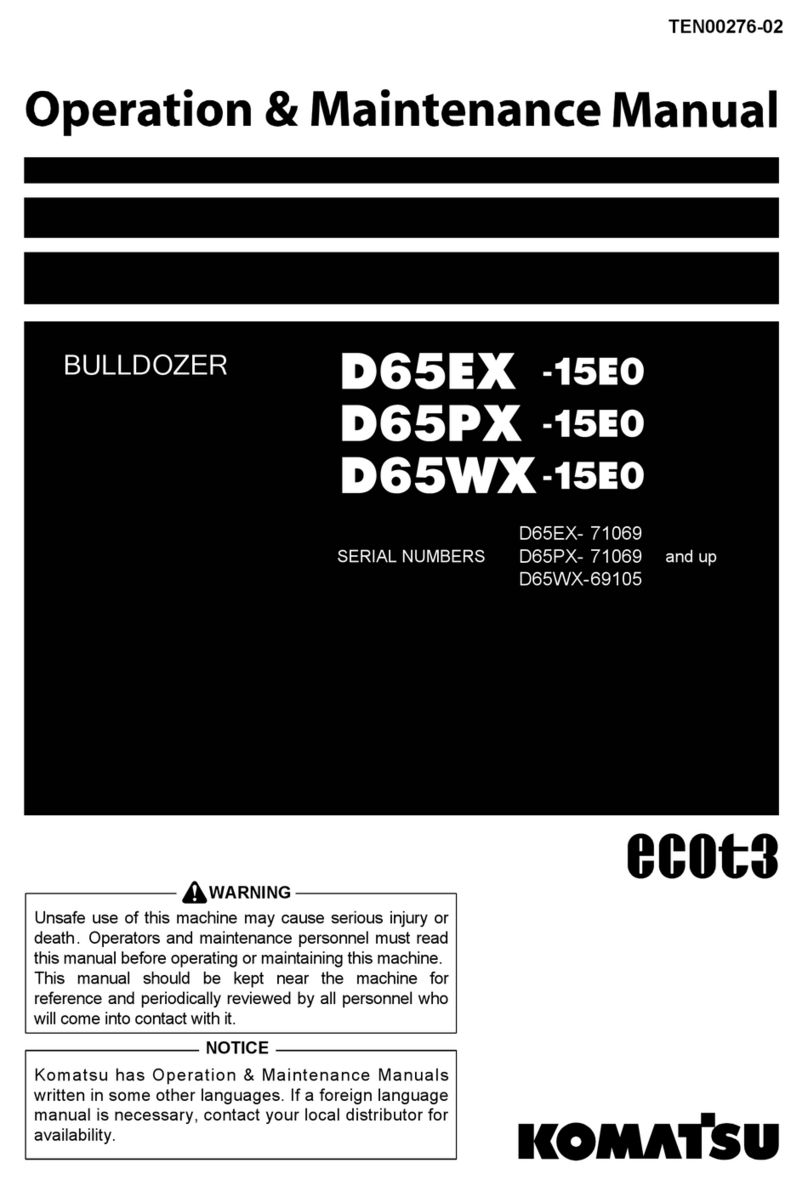
Komatsu D61EXi-24 Manual

D61EXi
-24
D61PXi
-24
SERIAL NUMBER
D61EXi-24 - 40001
and up
D61PXi-24 - 40001
and up
BULLDOZER
Unsafe use of this machine may cause serious injury or
death. Operators and maintenance personnel must read
this manual before operating or maintaining this
machine. This manual should be kept inside the cab for
reference and periodically reviewed by all personnel who
will come into contact with the machine.
Operation &
Maintenance Manual
EENAM03440
WARNING
ORIGINAL INSTRUCTIONS


FOREWORD
Komatsu recommends that any service parts used for maintenance, repair or
replacement of emission control systems be genuine new Komatsu or Ko-
matsu approved rebuilt parts or assemblies or others parts of equivalent
quality, and that the engine be serviced by an authorized Komatsu distribu-
tor. Failure to follow these recommendations could result in ineffective serv-
ice, damage to the product or safety risks (including personal injury or
death).
"Intelligent Machine Control" is ...
the system that utilizes ICT (Information Communication Technology) in each
stage of earth moving operation, such as survey, design, operation, supervi-
sion, examination and maintenance.
It enables the highly efficient and highly accurate earth moving operation by
utilizing information provided in each stage of operation. Utilizing the infor-
mation provided in the operation to the other operations enables better pro-
ductivity and quality in the whole operation.
1-1

BEFORE READING THIS MANUAL
Before reading this manual, read the Operation and Maintenance Manual of standard machine (D61EX-24,
D61PX-24).
This manual describes only the special device or function for D61EXI-24 and D61PXI-24. For the other part than
described in this manual, see the Operation and Maintenance Manual of standard machine.
This manual gives details of the operation and methods of inspection and maintenance for this machine that
must be observed in order to use the machine safely. Most accidents are caused by the failure to follow funda-
mental safety rules for the operation and maintenance of machines.
Read, understand and follow all precautions and warnings in this manual and on the machine before performing
operation and maintenance. Failure to do so may result in serious injury or death.
Komatsu cannot predict every circumstance that might involve a potential hazard when the machine is used.
Therefore, the safety messages in this manual and on the machine may not include all possible safety precau-
tions.
If you perform any operation, inspection, or maintenance under conditions that are not described in this manual,
understand that it is your responsibility to take the necessary precautions to ensure safety. In no event should
you or others engage in the prohibited uses or actions described in this manual. It is dangerous to perform im-
proper operation and maintenance of the machine. It may cause serious injury or death.
If you sell the machine, be sure to give this manual to the new owner together with the machine.
Always keep this Operation and Maintenance Manual in the indicated location so that all relevant personnel can
read it at any time.
Storage location for Operation and Maintenance Manual:
It is provided on the back side of the operator's seat back.
If this manual is lost or damaged, contact Komatsu or your Komatsu distributor and tell them about the machine
model name and the serial No. immediately to arrange for its replacement.
For details regarding the machine model name and the serial No., see the machine serial No. plate. In order to
arrange the proper Operation and Maintenance Manual, you will need to provide the machine model name and
the serial No.
This manual uses the International System of Units (SI) for units of measurement. For reference, units that have
been used in the past are given in { }.
The explanations, values, and illustrations in this manual have been prepared based on the latest information
available as of the date of its publication. Continuing improvements in the design of this machine may lead to
additional changes that are not reflected in this manual. If there is any question or suggestion, consult your Ko-
matsu distributor.
The numbers in the illustrations correspond to the numbers in ( ) in the text. (Example: 1 → (1))
Komatsu delivers machines that comply with all applicable regulations and standards of the country to which it
has been shipped. If this machine has been purchased in another country, it may lack certain safety devices and
specifications that are necessary for use in your country. If there is any question about whether your product
complies with the applicable standards and regulations of your country, consult your Komatsu distributor before
operating the machine.
BEFORE READING THIS MANUAL FOREWORD
1-2

SAFETY INFORMATION
To enable you to use the machine safely, and to prevent personal injury to operators, service personnel or by-
standers, the precautions and warnings included in this manual and the safety signs attached to the machine
must always be observed.
To identify important safety messages in the manual and on the machine labels, the following signal words are
used.
The "Safety Alert Symbol" identifies important safety messages on machines, in manuals, and elsewhere. When
you see this symbol, be alert to the risk of personal injury or death. Follow the instructions in the safety mes-
sage.
kk
DANGER
This signal word indicates an imminently hazardous situation which, if not avoided,
will result in death or serious injury.
kk
WARNING
This signal word indicates a potentially hazardous situation which, if not avoided,
could result in death or serious injury.
kk
CAUTION
This signal word indicates a potentially hazardous situation which, if not avoided,
may result in minor or moderate injury. It may also be used to alert against unsafe
practices that may cause property damage.
The following signal words are used to alert you to information that must be followed to avoid damage to the
machine.
NOTICE If precautions described are not observed, the machine may be damaged or the service life may
be reduced.
REMARK This word is used for information that is useful to know.
FOREWORD SAFETY INFORMATION
1-3

INTRODUCTION
MACHINE FEATURES
For this machine, current position information is obtained by using GNSS satellite and the base station. By using
the obtained current position information and information data for the operation, blade is automatically control-
led.
Under the blade automatic control, even if the operator does not operate the blade control lever, the blade auto-
matically moves along the preset design surface. By using this function effectively, you can easily build a ground
surface as designed.
When the load to blade increases, the blade is automatically raised to keep the constant targeted load by ad-
justing lifting amount, before the machine becomes impossible to travel forward. Therefore, this function can be
used not only for the finishing leveling but also the dozing and carrying operation.
Use this machine mainly for the following operation.
• Dozing work
• Leveling work
For detail of work procedure, see “PRECAUTIONS WHEN USING BLADE AUTOMATIC CONTROL (3-43)”.
This machine has the current ground display (as-built) function which grasps the ground shape under the track
as well as the operation and display it on the control box screen. By using this function, the progress of opera-
tion can be checked in real time on the control box screen.
In order to use the blade automatic control or current ground display (as-built) function, following device is need-
ed besides this machine.
• GNSS satellite (GPS, GLONASS)
Use it at a place under the open sky where has no obstacle.
• Base station
For the usable the base station, consult your Komatsu distributor in advance.
• Operation information data
Project file is necessary, which contains the data necessary for “intelligent Machine Control” such as the
design surface, base point, etc.
For details, consult your Komatsu distributor beforehand.
Observation items for use
• While the blade automatic control is in operation, the blade moves even if the operator does not operate the
blade control lever.
Before turning on the blade automatic control, check thoroughly if there are any persons or obstacles in the
area around the machine.
• While the blade automatic control is in operation, if the operator operates blade control lever, this blade lev-
er operation is given the priority and the blade moves as operated by the operator. When the operator stops
lever operation, the blade automatic control restarts.
While the blade automatic control is in operation, do not release your hand from the blade control lever, so
that you can avoid the danger immediately if any.
• When performing the inspection, maintenance, moving and loading/unloading on the trailer etc., i.e. other
operation than the operation by “intelligent Machine Control” at the jobsite, turn off the blade automatic con-
trol and turn off the control box power supply.
• You can turn off the blade automatic control by setting the work equipment lock lever to LOCK position.
INTRODUCTION FOREWORD
1-4

TABLE OF CONTENTS
FOREWORD.................................................................................................................................................... 1-1
BEFORE READING THIS MANUAL ......................................................................................................... 1-2
SAFETY INFORMATION .......................................................................................................................... 1-3
INTRODUCTION ...................................................................................................................................... 1-4
MACHINE FEATURES....................................................................................................................... 1-4
SAFETY........................................................................................................................................................... 2-1
SAFETY.................................................................................................................................................... 2-2
GENERAL PRECAUTIONS COMMON TO OPERATION AND MAINTENANCE ...................................... 2-3
PRECAUTIONS WHEN GETTING ON OR OFF MACHINE............................................................... 2-3
PRECAUTIONS FOR BLADE AUTOMATIC CONTROL .................................................................... 2-3
PRECAUTIONS FOR OPERATION .......................................................................................................... 2-5
START ENGINE................................................................................................................................. 2-5
PRECAUTIONS FOR MAINTENANCE..................................................................................................... 2-6
PRECAUTIONS FOR CHECK AND MAINTENANCE ........................................................................ 2-6
OPERATION .................................................................................................................................................... 3-1
GENERAL VIEW....................................................................................................................................... 3-2
MACHINE EQUIPMENT NAME ......................................................................................................... 3-2
MACHINE OUTSIDE EQUIPMENT NAME ........................................................................................ 3-2
CONTROLS AND GAUGES NAMES................................................................................................. 3-3
EXPLANATION OF COMPONENTS......................................................................................................... 3-5
INTELLIGENT MACHINE CONTROL SYSTEM................................................................................. 3-5
OTHER EQUIPMENT ...................................................................................................................... 3-14
MACHINE OPERATIONS AND CONTROLS .......................................................................................... 3-15
CHECKS AND ADJUSTMENT BEFORE STARTING ENGINE ........................................................ 3-15
OPERATIONS AND CHECKS AFTER STARTING ENGINE............................................................ 3-16
METHOD FOR STOPPING ENGINE ............................................................................................... 3-18
METHOD FOR USING AUTOMATIC BLADE CONTROL ................................................................ 3-20
TRANSPORTATION................................................................................................................................ 3-59
REMOVE RADIO DEVICE ANTENNA CABLE................................................................................. 3-59
PRECAUTIONS FOR LONG-TERM STORAGE ..................................................................................... 3-60
TURN BATTERY DISCONNECT SWITCH TO OFF POSITION BEFORE LONG-TERM STORAGE .......
..................................................................................................................................................... 3-60
TROUBLES AND ACTIONS ................................................................................................................... 3-62
OTHER TROUBLE........................................................................................................................... 3-62
HANDLE CONTROL BOX................................................................................................................................ 4-1
TABLE OF CONTENTS ............................................................................................................................ 4-2
INTRODUCTION ...................................................................................................................................... 4-4
KEYBOARD FUNCTIONS ................................................................................................................. 4-4
METHOD FOR DISPLAYING MAIN MENU........................................................................................ 4-6
FILE MENU............................................................................................................................................... 4-7
PROJECT FILES ............................................................................................................................... 4-7
CONTROL POINT FILES................................................................................................................. 4-12
LAYERS........................................................................................................................................... 4-15
POINT DATA.................................................................................................................................... 4-16
SURFACE FILE ............................................................................................................................... 4-17
ACTIVE FILE ................................................................................................................................... 4-30
EXIT 3DMC...................................................................................................................................... 4-31
CONTROL MENU................................................................................................................................... 4-32
MACHINE SETTING ........................................................................................................................ 4-32
METHOD FOR SETTING AS-BUILT CONTROL OPTIONS............................................................. 4-33
BLADE CONTROL........................................................................................................................... 4-38
STEER INDICATION OPTIONS....................................................................................................... 4-41
ADJUST WEAR AMOUNT ............................................................................................................... 4-41
DOZING CONTROL......................................................................................................................... 4-41
ADJUST BLADE ELEVATION .......................................................................................................... 4-41
CALIBRATE BLADE POSITION....................................................................................................... 4-41
FOREWORD TABLE OF CONTENTS
1-5

TOOLS MENU ........................................................................................................................................ 4-43
RADIO DEVICE SETTINGS............................................................................................................. 4-43
POSITION SETTINGS ..................................................................................................................... 4-43
NAVIGATE POINTS ......................................................................................................................... 4-44
TOPO SHOT FOR TOPOGRAPHIC SURVEY................................................................................. 4-46
SUPERVISOR MODE...................................................................................................................... 4-52
VIEW MENU ........................................................................................................................................... 4-58
MAIN WINDOW DISPLAY................................................................................................................ 4-58
LEFT WINDOW DISPLAY................................................................................................................ 4-59
RIGHT WINDOW DISPLAY ............................................................................................................. 4-60
LOWER WINDOW DISPLAY ........................................................................................................... 4-60
DISPLAY OPTIONS ......................................................................................................................... 4-61
3DMC............................................................................................................................................... 4-68
MAIN WINDOW DISPLAY....................................................................................................................... 4-69
ELEVATION CONTROL KEY ........................................................................................................... 4-69
SLOPE CONTROL KEY .................................................................................................................. 4-69
SHORTCUT ON THE MAIN WINDOW ............................................................................................ 4-71
TOOLBAR ON THE MAIN WINDOW ............................................................................................... 4-73
PAN OF MAIN MAP VIEW ............................................................................................................... 4-74
OPERATION ON MAIN MENU................................................................................................................ 4-75
METHOD FOR DISPLAYING GNSS INFORMATION....................................................................... 4-75
METHOD FOR ADJUSTING CUT/FILL OFFSETS .......................................................................... 4-77
METHOD FOR CHANGING GRADE INDICATOR DISPLAY............................................................ 4-78
METHOD FOR CHANGING DISPLAY OF LIGHT BAR.................................................................... 4-79
OPERATION USING POP-UP MENU .............................................................................................. 4-79
SPECIFICATIONS ........................................................................................................................................... 5-1
SPECIFICATIONS .................................................................................................................................... 5-2
SPECIFICATIONS : D61EXI-24 ......................................................................................................... 5-2
SPECIFICATIONS : D61PXI-24 ......................................................................................................... 5-2
INDEX.............................................................................................................................................................. 6-1
TABLE OF CONTENTS FOREWORD
1-6

SAFETY
This section describes cautions which are necessary to provide the efficient
operation with “intelligent Machine Control”.
Please follow the instructions described in the Operation and Maintenance
Manual for the standard machine for safety information of the whole ma-
chine.
2-1

SAFETY
GENERAL PRECAUTIONS COMMON TO OPERATION AND MAINTENANCE ............................................. 2-3
PRECAUTIONS WHEN GETTING ON OR OFF MACHINE...................................................................... 2-3
PRECAUTIONS WHEN STANDING UP FROM OPERATOR'S SEAT................................................ 2-3
PRECAUTIONS WHEN LEAVING MACHINE .................................................................................... 2-3
PRECAUTIONS FOR BLADE AUTOMATIC CONTROL ........................................................................... 2-3
PRECAUTIONS FOR OPERATION ................................................................................................................. 2-5
START ENGINE........................................................................................................................................ 2-5
IN COLD WEATHER.......................................................................................................................... 2-5
PRECAUTIONS FOR MAINTENANCE............................................................................................................ 2-6
PRECAUTIONS FOR CHECK AND MAINTENANCE ............................................................................... 2-6
PRECAUTIONS FOR GNSS ANTENNA............................................................................................ 2-6
HANDLE COMPONENT WHICH CONTAINS MERCURY.................................................................. 2-6
SAFETY SAFETY
2-2

GENERAL PRECAUTIONS COMMON TO OPERATION
AND MAINTENANCE
Mistakes in operation, inspection, or maintenance may result in serious personal injury or death. Before per-
forming operation, inspection, or maintenance, always read “Safety”, Operation and Maintenance Manual of
standard machines and this manual carefully and obey the warnings.
PRECAUTIONS WHEN GETTING ON OR OFF MACHINE
PRECAUTIONS WHEN STANDING UP FROM OPERATOR'S SEAT
Before standing up from the operator's seat to adjust the seat,
always perform the following. Turn off the automatic control of
blade. Lower the work equipment to the ground, set work
equipment lock lever (1) and parking brake lever (2) to LOCK
position (L), and stop the engine.
If the control levers are touched by mistake, there is danger
that the machine may suddenly move and cause serious per-
sonal injury or death.
PRECAUTIONS WHEN LEAVING MACHINE
If the proper procedures are not taken when parking the machine, the machine may suddenly move off by itself,
and this may lead to serious personal injury or death. Always observe the following.
When leaving the machine, always turn the automatic control of
blade OFF and lower the work equipment to the ground. Set
work equipment lock lever (1) and parking brake lever (2) to
LOCK position (L), and stop the engine. In addition, lock all pla-
ces and always take the key with you and leave it in the speci-
fied location.
PRECAUTIONS FOR BLADE AUTOMATIC CONTROL
• While the automatic control of blade is in operation, the blade moves even if the operator does not operate
the blade control lever.
Before turning the automatic control of blade ON, check thoroughly that there are no persons or obstacles
in the area around the machine.
• While the automatic control of blade is in operation, if the operator operates blade control lever, this blade
lever operation is given the priority and the blade moves as operated by the operator. When the operator
stops lever operation, the automatic control of blade restarts.
SAFETY
GENERAL PRECAUTIONS COMMON TO OPERATION AND MAINTE-
NANCE
2-3

While the automatic control of blade is in operation, do not release your hand from the blade control lever,
so that you can avoid the danger immediately if any.
• When performing the inspection, maintenance, moving and loading/unloading on the trailer etc., i.e. other
operation than the operation by “intelligent Machine Control” at the jobsite, turn off the automatic control of
blade, then turn off the control box power supply.
GENERAL PRECAUTIONS COMMON TO OPERATION AND MAINTE-
NANCE SAFETY
2-4

PRECAUTIONS FOR OPERATION
START ENGINE
IN COLD WEATHER
• If the work equipment is operated without sufficient warming-up operation of the machine, response of the
work equipment to movement of the control lever will be slow, and the work equipment may not respond as
the operator intends, so always perform the warming-up operation. Particularly in a cold weather, be sure
the warm-up operation is completed.
• If the machine is not thoroughly warmed up before turning on the automatic control of blade, the response
of the blade will be slow, or the blade will move suddenly and this may lead to unexpected accidents, so
always perform the warming-up operation. Particularly in a cold weather, be sure the warm-up operation is
completed.
• If the battery electrolyte is frozen, do not charge the battery or start the engine with a different power
source. There is a hazard that this will ignite the battery and cause the battery to explode.
Before charging or starting the engine with a different power source, melt the battery electrolyte and check
that there is no leakage of electrolyte before starting.
SAFETY PRECAUTIONS FOR OPERATION
2-5

PRECAUTIONS FOR MAINTENANCE
PRECAUTIONS FOR CHECK AND MAINTENANCE
• When performing the check and maintenance of the machine, turn off the automatic control of blade and
turn off the control box power supply.
If you perform the check while control box power supply is turned on, and you touch the Auto/Manual switch
accidentally, the automatic control of blade may be turned on, and the blade start moving, resulting in seri-
ous personal injury or death.
• Only when performing the check and adjustment for the automatic control of blade, turn on the control box
power supply, and perform the check and adjustment. Check that there are no persons or obstacles in the
area around the machine.
PRECAUTIONS FOR GNSS ANTENNA
• Cable connector of the GNSS antenna is looseness-free structure. Check is not needed.
• If the GNSS antenna contacts with obstacles during operation or traveling, and it has to be checked and
replaced, ask your Komatsu distributor.
• There is a danger of falling or tipping over that can lead to serious personal injury or death. Do not get on
the cab to check the GNSS antenna.
HANDLE COMPONENT WHICH CONTAINS MERCURY
The control box display backlight contains mercury. The machine may be equipped with optional High Intensity
Discharge lighting lamps which also may contain mercury. These components must be reused, recycled or
properly disposed of in accordance with applicable Local, State and Federal Laws.
PRECAUTIONS FOR MAINTENANCE SAFETY
2-6

OPERATION
This section describes cautions which are necessary to provide the efficient
operation with “intelligent Machine Control”.
Please follow the instructions described in the Operation and Maintenance
Manual for the standard machine for operation information of the whole ma-
chine.
3-1

GENERAL VIEW
MACHINE EQUIPMENT NAME
(1) Blade angle cylinder (with stroke sensor)
(2) GNSS antenna
(3) Radio antenna
(4) Blade tilt cylinder (with stroke sensor)
(5) Blade lift cylinder (with stroke sensor)
MACHINE OUTSIDE EQUIPMENT NAME
(1) GNSS satellite (GPS)
(2) GNSS satellite (GLONASS)
(3) Base station
GENERAL VIEW OPERATION
3-2

CONTROLS AND GAUGES NAMES
(1) Control box
(2) Auto/Manual switch
(3) ICT sensor controller (inside the cover)
(4) GNSS receiver (inside the cover)
(5) GNSS radio device
(6) Cut/Fill offsets switch (Up)
(7) Cut/Fill offsets switch (Down)
(8) Back grade mode switch
OPERATION GENERAL VIEW
3-3

CONTROL BOX NAME
(1) Elevation control key
(2) Cut/Fill offsets
(3) Left window
(4) Main window
(5) Take a topo shot
(6) Blade load selection
(7) Dozing mode selection
(8) Start/Stop As-built updates
(9) Toggle As-built mode
(10) iB logo key
(11) Zoom in key
(12) Zoom out key
(13) Toggle main view
(14) Right window
(15) Lower window
(16) Slope control key
(17) Back grade mode indicator
(18) AUTO indicator
REMARK
The above figure shows a typical example of the control box main window.
The contents displayed on the screen depends on the setting.
For detail, see “HANDLE CONTROL BOX (4-1)”.
GENERAL VIEW OPERATION
3-4

EXPLANATION OF COMPONENTS
The following is an explanation of devices necessary to operate the machine.
To perform suitable operations correctly and safely, it is important to completely understand methods of operat-
ing the equipment, and the meanings of the displays.
INTELLIGENT MACHINE CONTROL SYSTEM
CONTROL BOX
kk
WARNING
To prevent the blade from moving suddenly, turn on the control box power only when performing work
with “intelligent Machine Control”.
The control box has 2 functions, a function to set or adjust the design surface to be used for the blade automatic
control, and a function to display the GNSS satellite information. Touch the screen directly to operate it.
(1) Power ON switch (green)
(2) Power OFF switch (red)
(3) USB port
For detail, see “HANDLE CONTROL BOX (4-1)”.
• Place the machine on a level ground under the open sky, turn on the power of base station, and then turn
on the control box power supply to perform the inspection.
• If the control box starts operation on the slope of which pitching angle (inclination in front or rear) or rolling
angle (inclination in right or left) is 20 ° or more, accuracy of it may deteriorate. Start the control box on a
level place.
• The power supply of the control box is not linked with the starting switch of the machine. Before starting
check or work with “intelligent Machine Control”, press power ON switch (green) (1) to turn on the control
box power.
Also, after finishing check or work with “intelligent Machine Control”, press power OFF switch (red) (2) to
turn off the control box power.
OPERATION EXPLANATION OF COMPONENTS
3-5

REMARK
• There is no priority in order between switching on/off of control box power supply and switching on/off of
starting switch of the machine.
• The control box operates on Windows® operating system.
After turning on the control box power supply, it takes approximately 2 minutes until Windows® operating
system starts and the main window is displayed. In the same way, after turning off the control box power
supply, it takes approximately 2 minutes until the main window is finished and Windows® operating system
shuts down.
(Windows is a registered trademark of Microsoft Corporation in the United States and/or other countries.)
AUTO/MANUAL SWITCH
kk
WARNING
• While the blade automatic control is in operation, the blade moves even if the operator does not op-
erate the blade control lever.
Before turning on the blade automatic control, check thoroughly if there are any persons or obsta-
cles in the area around the machine.
• While the blade automatic control is in operation, if the operator operates blade control lever, this
blade lever operation is given the priority and the blade moves as operated by the operator. When
the operator stops lever operation, the blade automatic control restarts.
While the blade automatic control is in operation, do not release your hand from the blade control
lever, so that you can avoid the danger immediately if any.
• When performing the inspection, maintenance, moving and loading/unloading on the trailer etc., i.e.
other operation than the operation by “intelligent Machine Control” at the jobsite, turn off the blade
automatic control and turn off the control box power supply.
• You can turn off the blade automatic control by setting the work equipment lock lever to LOCK posi-
tion.
Auto/Manual switch is used for turning on or off the blade auto-
matic control.
Auto/Manual switch is located on the blade control lever.
When turning on the blade automatic control
Place the work equipment lock lever in FREE position (F), and
press Auto/Manual switch once.
The blade automatic control is turned on.
EXPLANATION OF COMPONENTS OPERATION
3-6
This manual suits for next models
1
Table of contents
Other Komatsu Construction Equipment manuals

Komatsu
Komatsu HD785-7 Quick start guide

Komatsu
Komatsu XT430-3 Manual

Komatsu
Komatsu WD600-3 Manual

Komatsu
Komatsu D51EXi-24 Manual

Komatsu
Komatsu 06253 Manual

Komatsu
Komatsu Super D155AX-3 Manual

Komatsu
Komatsu PC4000 Manual

Komatsu
Komatsu WA95-3 Manual

Komatsu
Komatsu D85EX-15 Manual

Komatsu
Komatsu GALEO D65EX-15 Manual

Komatsu
Komatsu D375A-8 Manual

Komatsu
Komatsu D32E-1 Install guide

Komatsu
Komatsu BR380JG-1E0 Install guide

Komatsu
Komatsu D65EXi-18 Manual

Komatsu
Komatsu ecot3 WA500-6 Install guide

Komatsu
Komatsu D31EX -22 Manual

Komatsu
Komatsu PC3000-6 Manual

Komatsu
Komatsu Avance Loader WA900-3 Manual

Komatsu
Komatsu ecot 3 Manual

Komatsu
Komatsu 830E-1AC Manual