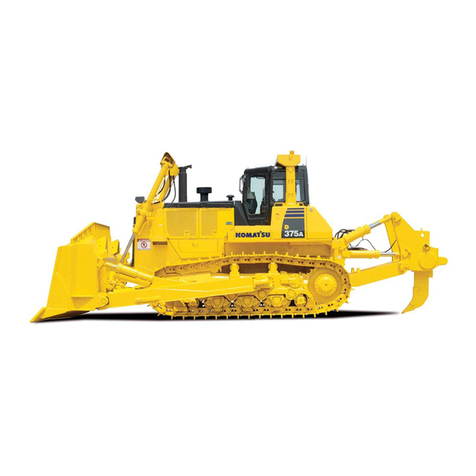
Overall Maximum Maximum Maximum Weight
length with Blade Blade lift above drop below tilt Dozer Hydraulic Ground
dozer capacity length x height ground ground adjustment equipment oil pressure*
Semi-U tilt 6930 mm 13.7 m34300 mm x 1960 mm 1450 mm 640 mm 1000 mm 7478 kg 29 kg 118 kPa
dozer 22'9" 17.9 yd314'1" x 6'5" 4'9" 2'1" 3'3" 16,490 lb 64 lb 1.20 kgf/cm2 17.1 psi
U tilt dozer 7265 mm 16.6 m34615 mm x 1973 mm 1450 mm 640 mm 1070 mm 8404 kg 29 kg 120 kPa
23'10" 21.7 yd315'2" x 6'6" 4'9" 2'1" 3'6" 18,530 lb 64 lb 1.22 kgf/cm217.3 psi
Dual tilt 6930 mm 13.7 m34300 mm x 1960 mm 1450 mm 640 mm 1140 mm 7555 kg 35 kg 118 kPa
Semi-U dozer 22'9" 17.9 yd314'1" x 6'5" 4'9" 2'1" 3'9" 16,660 lb 77 lb 1.20 kgf/cm217.1 psi
Dual tilt 7265 mm 16.6 m34615 mm x 1973 mm 1450 mm 640 mm 1220 mm 8481 kg 35 kg 118kPa
U-dozer 23'10" 21.7 yd315'2" x 6'6" 4'9" 2'1" 4'0" 18,700 lb 77 lb 1.22 kgf/cm217.3 psi
Blade capacities are based on the SAE recommended practice J1265.
* Ground pressure shows tractor, cab, ROPS canopy operator, giant ripper standard equipment and applicable blade.
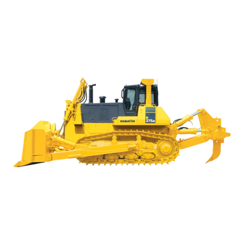
SEMI-U DOZER WITH GIANT RIPPER
Tractor weight . . . . . . . . . . . . . . . . . . . . . . . . . . . 37680 kg 83,070 lb
Including rated capacity of lubricant, coolant, full fuel tank,
operator, and standard equipment.
Operating weight. . . . . . . . . . . . . . . . . . . . . . . . 49850 kg 109,900 lb
Including Semi-U tilt dozer, giant ripper, steel cab,
ROPS, operator, standard equipment, rated capacity of
lubricant, coolant, and full fuel tank.
Closed-center load sensing system (CLSS) designed for precise and
responsive control, and for efficient simultaneous operation.
Hydraulic control units:
All spool valves externally mounted beside the hydraulic tank.
Plunger type hydraulic pump with capacity (discharge flow) of 230 ltr
60.8 U.S. gal/min at rated engine rpm.
Relief valve setting . . . . . . . . . . . . . 27.5 MPa 280 kg/cm23,980 psi
Control valves:
Spool control valves for Semi-U tilt dozer and Full-U tilt dozer
Positions: Blade lift . . . . . . . . . . . . . . Raise, hold, lower, and float
Blade tilt. . . . . . . . . . . . . . . . . . . . . Right, hold, and left
Additional control valve required for variable digging angle multi-
shank ripper and giant ripper.
Positions: Ripper lift . . . . . . . . . . . . . . . . . . Raise, hold, and lower
Ripper tilt. . . . . . . . . . . . . Increase, hold, and decrease
Hydraulic cylinders . . . . . . . . . . . . . . . . . . . . . . Double-acting, piston
Hydraulic oil capacity (refill):
Semi-U tilt dozer . . . . . . . . . . . . . . . . . . . . . 130 ltr 34.3 U.S. gal
U tilt dozer . . . . . . . . . . . . . . . . . . . . . . . . . 130 ltr 34.3 U.S. gal
Ripper equipment (additional volume):
Giant ripper. . . . . . . . . . . . . . . . . . . . . . . . . . 38 ltr 10.0 U.S. gal
Multi-shank ripper . . . . . . . . . . . . . . . . . . . . 38 ltr 10.0 U.S. gal
Number of cylinders Bore
Blade lift 2 120 mm 4.72"
Blade tilt 1 180 mm 7.09"
Ripper lift 2 180 mm 7.09"
Ripper tilt 2 160 mm 6.30"
A2260 mm 7'5"
B4300 mm 14'1"
C3965 mm 13'0"
D1960 mm 6'5"
E3480 mm 11'5"
F9290 mm 30'6"
G3060 mm 10'0"
H1420 mm 4'8"
I1195 mm 3'11"
J3985 mm 13'1"
Ground Clearance: 507 mm 1'8"
10
COOLANT AND LUBRICANT
CAPACITY (REFILL)
Fuel tank. . . . . . . . . . . . . . . . . . . . . . . . . . . . . 840 ltr 222 U.S. gal
Coolant . . . . . . . . . . . . . . . . . . . . . . . . . . . . . . 130 ltr 34.3 U.S. gal
Engine . . . . . . . . . . . . . . . . . . . . . . . . . . . . . . 52.0 ltr 13.7 U.S. gal
Torque converter, transmission,
bevel gear, and steering system . . . . . . . . . . 90 ltr 23.8 U.S. gal
Final drive (each side). . . . . . . . . . . . . . . . . . . . 40 ltr 10.6 U.S. gal
D275A-5
Power Shift
DRAWBAR PULL vs. SPEED
MAXIMUM USABLE PULL
DEPENDS ON TRACTION AND
WEIGHT OF TRACTOR
INCLUDING MOUNTED
EQUIPMENT
FINAL DRIVES
Double-reduction final drive of spur and planetary gear sets to
increase tractive effort and reduce gear tooth stresses for long final
drive life. Segmented sprocket rims are bolt-on for easy replacement.
ENGINE
Model . . . . . . . . . . . . . . . . . . . . . . . . . . . . . . . Komatsu SDA6D140E
Type . . . . . . . . . . . . . . . . . . . . 4-stroke, water-cooled, direct injection
Aspiration . . . . . . . . . . . . . . . . . . . . . . . . . Turbocharged, aftercooled
No. of cylinders . . . . . . . . . . . . . . . . . . . . . . . . . . . . . . . . . . . . . . . . 6
Bore x stroke . . . . . . . . . . . . . . . . . 140 mm x 165 mm 5.51" x 6.50"
Piston displacement. . . . . . . . . . . . . . . . . . . . . . . . . 15.24 ltr 930 in3
Flywheel horsepower
SAE J1349. . . . . . . . . . . . . . . . . . . . 306 kW 410 HP at 2000 rpm
DIN 6270 . . . . . . . . . . . . . . . . . . . . . 306 kW 416 PS at 2000 rpm
Governor . . . . . . . . . . . . . . . . . . . . . . . . . . . . . . All-speed, electronic
Lubrication system
Method . . . . . . . . . . . . . . . . . . . . . . . Gear pump, force lubrication
Filter . . . . . . . . . . . . . . . . . . . . . . . . . . . . . . . . . . . . . . . . Full-flow
TORQFLOW TRANSMISSION
Komatsu TORQFLOW transmission consists of a water-cooled,
3-element, 1-stage, 1-phase, torque converter and a planetary gear,
multiple-disc clutch transmission which is hydraulically-actuated and
force-lubricated for optimum heat dissipation. Gearshift lock lever and
neutral safety switch prevent accidental starts.
STEERING SYSTEM
PCCS lever controls for all directional movements. Pushing the
PCCS lever forward results in forward machine travel, while pulling it
rearward reverses the machine. Simply tilt the PCCS lever to left to
make a left turn.
PCCS lever, joystick controlled wet multiple-disc steering clutches,
hydraulically loaded and hydraulically released. Wet multiple-disc,
pedal/lever controlled steering brakes are spring loaded hydraulically
released and require no adjustment. Steering clutches and brakes
are interconnected for easy, responsive steering.
Minimum turning radius . . . . . . . . . . . . . . . . . . . . . . . . . 3.9 m 12'10"
UNDERCARRIAGE
Suspension . . . . . . . . . . . . . Oscillating equalizer bar and pivot shaft
Track roller frame. . . . . . . . . . . . . . . Cylindrical, high-tensile-strength
steel construction
Rollers and idlers. . . . . . . . . . . . . . . . . . . . . . Lubricated track rollers
K-bogie Undercarriage
Lubricated track rollers are resiliently mounted to the roller
frame with a series of K-bogies whose oscillating motion
is cushioned by rubber pads.
Extreme Service Track shoes
Lubricated tracks. Unique seals prevent entry of foreign
abrasive material into pin to bushing clearances to provide
extended service life. Track tension is easily adjusted with grease
gun.
No. of shoes (each side) . . . . . . . . . . . . . . . . . . . . . . . . . . . . . . . . 39
Grouser height:
Single grouser . . . . . . . . . . . . . . . . . . . . . . . . . . . . . . 88 mm 3.5"
Shoe width (standard) . . . . . . . . . . . . . . . . . . . . . . . . . . 610 mm 24"
Ground contact area . . . . . . . . . . . . . . . . . . . . . 42456 cm26,580 in2
Ground pressure (bulldozer) . . . . . . . . 118 kPa 1.20 kg/cm217.1 psi
No. of track rollers. . . . . . . . . . . . . . . . . . . . . . . . . . . . . . . . . . . . . . 7
No. of carrier rollers . . . . . . . . . . . . . . . . . . . . . . . . . . . . . . . . . . . . 2
DIMENSIONS
OPERATING WEIGHT
HYDRAULIC SYSTEM
DOZER EQUIPMENT


