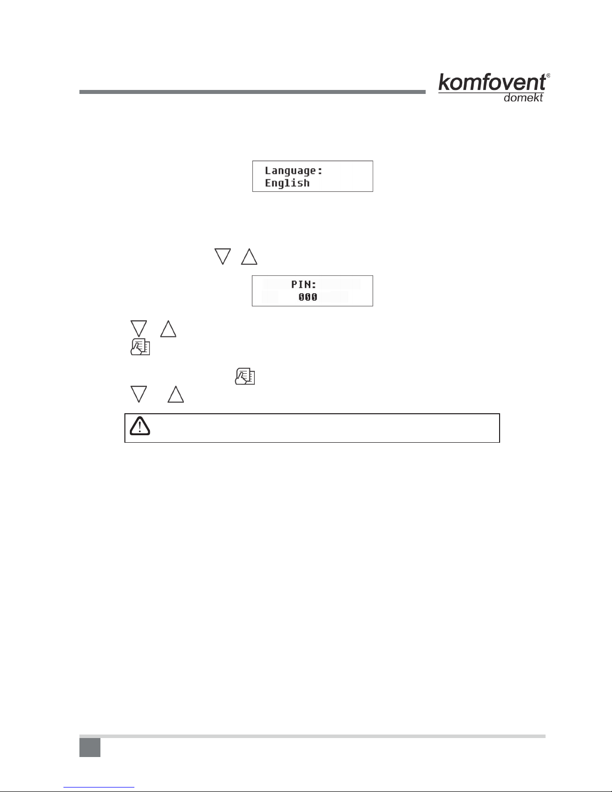
Komfovent DOMEKT series User manual

DOMEKT
Series Air Handling Units with C4 PLUS Controller
Electrical Installation and Operation Manual
EN

2
1. INSTALLATION MANUAL .....................3
1.1. Electric Power Supply Connection .....................3
1.2. Control Panel Installation .....................3
1.3. Kitchen Hood Installation .....................4
1.4. Control Contacts Connection .....................4
2. OPERATION MANUAL .....................5
2.1. Unit Control .....................5
2.2. Switching on the Unit .....................6
2.3. Control Panel Indication .....................6
2.4. Quick Ventilation Level Switchover .....................7
2.5. Unit Programmable Settings .....................7
2.6. OVR function ................... 11
2.7. Conguration of automation functions ................... 11
2.8. Troubleshooting ...................12
Unit Functional Diagram ...................14
Wiring Diagram ...................15
Table of Contents

3
Installation Manual
1. INSTALLATION MANUAL
Installation works can be performed only by the specialists that have required qualication. During installation
following requirements must be fullled.
It is recommended to lay control cables separately from power cables in a distance
no less than 20 cm.
1.1. Electric Power Supply Connection
Air handling unit voltage is 230V AC; 50 Hz , therefore it is necessary to install the socket with grounding of
corresponding capacity (see wiring diagram). Electric power supply cable type is indicated in electric diagram.
Unit must be connected to the stationary installation by solid cable through 10A
circuit breaker with maximum 30mA current leakage relay.
Before connecting unit to the electrical power supply, it is necessary to check
whether earthing has been installed properly in conformance with electric safety
requirements.
1.2. Control Panel Installation
1. Control panel must be installed in the room under given following conditions:
• ambient temperature 00C ... 400C;
• relative humidity limits 20% ... 80%;
• protection must be ensured from accidentally vertically falling water drops (IP X2).
2. Installation height must be not less than 0,6m from the ground.
3. Control panel connection is projected through the hole in its backside (see 1.2 Picture).
4. Control panel is xed after screwing two holes on the fastening surface.
1.2 Picture
Control Panel Connection
When closing the panel window, do not bend the springs inside as this may inhibit
the functions of the panel buttons! Disconnect power supply prior to connecting the
control panel!
The length of cable connecting control panel and air handing unit can not exceed
150 m. Electric power supply cable type is indicated in wiring diagram.

4
Installation Manual
1.3. Kitchen Hood Connection
Air handling units KOMFOVENT DOMEKT REGO 200VE have possibility of kitchen hood connection (in the
functional diagram it is marked by KH). After shing the cable through the rubber gasket, (located in the wall) it
has to be connected to connection box J11.
Connector connection is performed strictly according to numeration given in
wiring diagram, or adequate markings (see wiring diagram).
When disconnecting unit sections, do not pull by connecting wires and cables!
Before starting any operations inside the unit, make sure that the unit is switched
off and the power supply voltage is shut off.
1.3 Picture
Kitchen Hood Connection
1.4. Control Contacts Connection
Air handling units with the C4 controller have the connection of additional device (switch, sensor, timer, button
etc). For this function external cable is brought out from the unit (see 1.4 Picture). Detailed description of connec-
tion possibilities is provided in chapter 2.6.
1.4 Picture
Connection of additional control device

5
Operation Manual
2. OPERATION MANUAL
2.1. Unit Control
Air handling units control system ensures control of the physical processes that are taking place inside the air
handling unit. Control system consists of:
• controller board;
• fuses, power and intermediate control boards, which are installed inside the unit;
• control panel, which can be installed in the convenient place for the user;
• air damper actuators;
• pressure and temperature sensors.
Control panel (2.1 Picture) is designed for remote air handling unit control, setting and display of controller
parameters. Control panel LCD display with backlight allows monitoring various parameters and text messages.
Controller light signals indicate unit operation modes and failures. Air temperature, ventilation intensity, operation
modes and other parameters are set by the touch sensitive buttons.
2.1 Picture
General View of the Control Panel
Touch sensitive buttons located on the panel mean:
start up and shut down of the air handling unit / return to previous menu window;
entry to parameters change menu / set parameters conrmation;
navigation in the menu / parameters value change.
2.2. Switching on the Unit
After connecting the unit to the electrical power supply, on the control panel LCD displays start-up window, this
is shown in the Picture 2.3.
Unit is switched on (off) by touching and holding button for 4 seconds till sound conrms the action. Unit
operation is indicated in the control panel by ventilation intensity and LED signals (see further).

6
Operation Manual
2.3. Control Panel Indication
Data is presented to the user on the control panel LCD display by numbers and text messages, also by two
colour LED signals.
Controller display start-up window is shown in the 2.3 Picture.
2.3 Picture
Control Panel Start-Up Window
Light Diode Indication:
1. No LED signal indication on the panel – unit has been switched off.
2. LED shines steady green and text message is shown – unit is switched on.
3. Automatic mode symbol is shown on the panel, while green LED shines – unit is operating in automatic
mode according to weekly schedule.
4. LED blinks red and green and text message is shown – see 2.9 chapter.
5. LED shines steady red and text message is shown – emergency unit shut down (see 2.9 chapter).
6. Nothing is showing on the control panel - unit does not have electric power supply.
Note: By pressing any button on the panel automatically switching on the display backlight. Backlight is off after
30 seconds when no buttons are pressed.
2.4. Quick Ventilation Level Switchover
Three ventilation levels are projected in the unit. Each of them has its intensity (more detailed settings see in
the next chapter). There is possibility to switch ventilation level quickly from start-up window (2.3 Picture).
To increase ventilation intensity: touch and hold and at the same moment increase ventilation intensity
by touching button.
To decrease ventilation intensity: touch and hold and at same moment decrease ventilation intensity
by touching button.
If ventilation intensity is changed using quick switchover and unit is operating
according to weekly schedule, operation mode automatically is changed to
manual mode.
Unit operation indication LED
Setting temperature (+15 … 300C)
Current season (Winter / Summer)
Time
Ventilation level (0,1, 2, 3)
Supply air temperature
Automatic mode symbol

7
Operation Manual
2.5. Unit Programmable Settings
By soft touching button the parameters menu is entered. Menu window is selected by buttons ,
(see further description). When menu window is selected, touch for selecting desirable parameters and se-
lect the value with , . To conrm the changes touch .
To return to previous menu or to start-up window touch button.
Note: If touch sensitive buttons are inactive for 1 minute, start-up window is shown.
1. Unit operation modes setting
Two unit operation modes are possible: manual and automatic. In manual mode unit operates continuously by
set ventilation intensity. In automatic mode unit works according to weekly schedule (see further weekly schedule
setting).
Note: If automatic operating mode is selected, there is a symbol in the start-up window.
2. Setting ventilation level
Air handling units with AC-type fans have three ventilation levels, each of which can be set for manual and
automatic operation mode.
To set the ventilation level in manual mode, select menu window:
1 – minimum ventilation intensity level
2 – normal ventilation intensity level
3 – maximum ventilation intensity level
Normal (second) intensity level of ventilation for the supply air and separately for the exhaust air fan can be
adjusted in three steps according to a specic ventilation system design:
I – minimum value
II – medium value
III – maximum value
Ventilation equipment with the EC type fan also has three levels of ventilation. Fan intensity for every of the
free levels can be attributed separately for the supplied and exhausted air from 20 to 100%, in 1% steps.
Intensity potentiometers on the automation box inside the air handling unit are not
used, their settings have no effect for the unit control when a control panel with
touch-sensitive buttons is connected.

8
Operation Manual
3. Activation of the OVR function
Air handling units have the OVR function, which detailed description can be found in chapter 2.6. The OVR
function can be activated in two ways:
1. By the external control device. Connection is described in chapter 1.4. After interconnecting (short-
circuiting) the FC contacts (see the electrical diagram), the unit will operate in the selected OVR mode and after
disconnection it will return to the previous operation mode.
2. By control panel. In this case there is no need for additional connections to external control devices, the
function is activated from the panel, and the unit will operate in the chosen OVR mode until the internal timer is
active (from 1 to 90 minutes):
“On” - OVR function on.
“Off” - function off.
If the OVR function is active, the start-up window of the remote panel shows the 4th ventilation level. When
this function is active, the intensities of the supplied air and separately for the exhausted air fans can be adjusted
in the menu window „Ventilation“ from 20 to 100% (EC fans only).
4. Setting temperature value
Air handling unit maintains the user-dened temperature. The temperature setting is selected on the menu
window:
Intensity potentiometer on the automation box inside the air handling unit is not
used, its settings have no effect for the unit control when a control panel with
touch-sensitive buttons is connected.
5. Setpoint sliding
The setpoint can be shifted from -9 to +9°C from the temperature set value at specied by user time period. To
set setpoint sliding select menu window:
6. Season setting
For the air handling unit operating in most economical mode, summer and winter seasons have been provided.
• By setting “Winter” season, the heater operation is permitted.
• By setting “Summer” season, the heater operation is not permitted.
To set season select menu window:
Note: If air temperature during summer season is insufcient, air handling unit can be preset and for “Winter”
season mode, its energy expenditures will be minimal.

9
Operation Manual
7. Day and time setting
For the unit proper operation in automatic mode according to preset weekly schedule the day of the week and
time should be set:
Days notation:
Mo – Monday
Tu –Tuesday
We – Wednesday
Th – Thursday
Fr – Friday
Sa – Saturday
Su – Sunday
8. Weekly schedule setting
Two ways for weekly schedule setting have been projected:
• “1-5/6,7” - simplied schedule setting option: one schedule for all work days and the other for weekend operation;
• “1-7” - weekly schedule setting option: different operation schedule for each day.
There is one operation schedule with two setting options.
After selecting program for each day of the week “1-7” schedule setting window is introduced:
Each day of the week has 3 events: N1, N2, N3. Settings start from Monday (Mo). When the event of the day
is selected, event start and end time is set and ventilation intensity level (0, 1, 2, 3) is assigned.
Before selecting work days and weekend operation mode schedule “1-5/6,7” menu window is introduced:
After event (N1, N2, N3) is selected for work days “1-5”, each event start and end time and ventilation intensity
is set the same way. The same way three unit operating events are set for the weekend:
Note: Every event start and end time is set from 0:00 to 24:00 h.
For instance:
Monday:
N1 from 00:00 to 07:00 2 ventilation level
N2 from 10:00 to 20:00 1 ventilation level
N3 from 20:00 to 24:00 3 ventilation level

10
9. Language setting
Language selection menu has been projected on the control panel. To set language the last menu window
should be selected:
10. Menu locking
The PIN code is provided to lock entering to the parameters setting menu. If the menu is locked, only main
parameters can be reviewed also the unit may be switched on or off.
To enter the PIN code, touch + and hold for 4 seconds till corresponding window appears:
To enter the PIN code follow these steps:
1. Touch or to enter the rst digit.
2. Touch to go to the second digit.
3. Repeat the steps above to enter the second and the third digits.
4. After third digit is entered touch to conrm the code.
5. Touch and and hold for 4 seconds to save the code into controller memory.
The menu can be unlocked only with the PIN code. If the code is forgotten,
contact local service team.
2.6. OVR function
OVR (Override) function is intended for remote unit control by an additional external device. After the activation
of this function the current mode of operation will be ignored and the unit will operate at a set intensity.
Applications of the OVR function:
• Maintenance of CO2quantity in room – by adding an additional CO2sensor (with relay), the main user-set
ventilation rate at higher CO2will be switched to the maximum intensity until the room is ventilated, and then again
will return to the user-dened intensity.
• Maintaining relative humidity in the room – after contacting the external relative humidity sensor (with
relay), automatically switching to maximum or different set ventilation intensity the humidity level desired by the
user will be maintained.
• Ventilation on demand – when the motion sensor is connected to the control contacts, ventilation will
be adjusted according to demand, i.e. if people are indoors, ventilation will be carried out according to the set
OVR intensity and if there‘s nobody in the room - the unit will operate according to the main user intensity, for
example, the minimum.
• Ventilation with additional air extraction – connection of additional extracting device, for example, a kitchen
hood or other extraction device without a separate fan, is intended, thus the air extraction is carried out by the unit itself.
After the activation of the function the supply and exhaust air fans start operating at maximum intensity.
Operation Manual

11
Operation Manual
• Negative pressure compensation – intended for systems where air extraction can be carried out in a
separate air extraction fan. Thus, for the compensation of negative pressure in room, the OVR function can be
activated by separate control contacts. After the activation of the function, only supply fan starts operating at
maximum intensity and the exhaust air fan goes off.
Note: To make this function work, namely to stop the exhaust air fan in the OVR mode, the jumper No 4 on the
automation box should be ON (2.7. Picture).
2.7. Conguration of automation functions
Switches (2.7. Picture) on the automatic box can be used for the selection of heat exchanger type, heater and
fan, and the OVR function mode. Settings take effect only after rebooting the power supply.
Switch No. ON OFF
1 Rotary heat exchanger Plate heat exchanger
2 Water heater Electric heater
3 EC fans AC fans
4 OVR mode when the exhaust air fan is off Usual OVR mode
2.7 Picture
Automation conguration switches

12
Operation Manual
2.8. Troubleshooting
If the unit is inoperative:
• Make sure the feeding cable is plugged into an electrical outlet.
• Check all safety fuses of the automatic control block. In case of need, replace the faulty fuses with the new
ones of the same electric parameters (fuses parameters are in wiring diagram).
• Make sure there is no failure message in the control panel. If there is a problem, you must rst remove it.
To remove the problem, follow the table 2.8 describing failures.
• If nothing is shown on the control panel, check the cable that connects the remote panel to the unit.
If air ow is reduced:
• Check set ventilation intensity level (see chapter 2.5.).
• Check air lters‘ condition. If needed, replace with the new ones.
• Check supply/exhaust air diffusers adjustment.
• Check for clogging outside air intake grille.
• Check if system ducting is not damaged and there are no extraneous things inside.
If supplied air is too cold:
• Check temperature setting (see chapter 2.5.).
• Check if „Winter“ mode is set on the panel.
• Check if there is no failure indication on the control panel (see table 2.8.).
• Check fuse F2 located on the automatic box.
If the unit has been stopped and there is red light diode signal on the controller,
and text message is shown meaning failure, failure needs to be eliminated!
Before starting any operations inside the unit, make sure that the unit is
switched off and the power supply voltage is shut off.
After failure has been eliminated and power supply connected, text message appears about previous failure. If
there are no more failures, unit is switched on by pressing button; unit continues operating by preset mode.
However if the failure has not been eliminated, unit either starts operating and after some time it stops again, or it
does not operate and failure message is indicated.

13
2.8 Table
Failures indicated on the control panel,
possible reasons and it elimination
Message LED Protection tripping description Possible Failure Cause Failure Elimination
Red and green
blinking
Depending on the intensity of unit operation,
at a certain time a periodic inspection mes-
sage appears on the control panel.
-
After disconnecting the unit from power
supply, it is necessary to carry out periodic
inspection of the unit, i.e. to check the air
lter clogging and the condition of the heat
exchanger, the heater and fans.
Red light
If the supply air temperature falls below the per-
mitted value: +5°C, unit will stop operating with
10 min. delay.
Malfunction of the heat
exchanger and/or heater.
Check temperature and season settings.
Check the heat exchanger and heater
operation.
Red light
If the supply air temperature is above the per-
mitted value: +45°C, unit will stop operating with
10 min. delay.
Malfunction of the heat
exchanger and/or heater.
Check temperature and season settings.
Check the heat exchanger and heater
operation.
Red and green
blinking
Unit with electric heater has protection from
overheating at 90°C, which can be activated
if the heater blow-cooling is insufcient. Unit
operation is not terminated.
Heater is disconnected due
to low air ow.
When heater cools down, protection restores
automatically. It is recommended to increase
ventilation intensity level.
Red light
Unit with electric heater has emergency pro-
tection from overheating at 120°C, which can
be activated in case of the heater failure. Unit
operation is terminated.
Electric heater overheating
protection is on.
It is possible to restore emergency overheat-
ing protection with button “RESET” (located
on the heater), only if before heater over-
heating cause has been claried and elimi-
nated.
Red light
In the unit with water heater, when the water
temperature falls below the permitted value of
+9°C, the unit will stop operating.
Failure of the hot water
preparation and supply func-
tion in the heating system.
Check circulation pump and heating system
condition, heating valve actuator perfor-
mance.
Red light
In the unit with plate heat exchanger, if the
freezing protection of the heat exchanger is
activated and is not restored in 10 min, the unit
will stop operating.
Temperature of the air
passing through plate heat
exchanger, dropped lower
allowable level.
Check by-pass damper condition and ac-
tuator performance. It is recommended to
decrease ventilation level.
Red light
When there is no signal from the rotor’s rotation
sensor, if the “Winter” season is set, the unit will
stop operating in 2 min.
The belt is broken, failure
of the rotor motor or rotor
sensor.
Check rotor drive and rotation sensor condi-
tion.
Red and green
blinking
When there is no signal from the rotor’s rotation
sensor, if the “Summer” season is set, the warn-
ing message appears in 2 min. on the control
panel. The unit operation is not terminated.
The belt is broken, failure
of the rotor motor or rotor
sensor.
Check rotor drive and rotation sensor condi-
tion.
Red light
When temperature exceeds the maximum
permitted limits: -30°C...+75°C, the unit stops
operating immediately.
Supply air temperature sen-
sor is not connected or bro-
ken down.
It is necessary to check sensor connections
or change the sensor.
Operation Manual

14
Unit Functional Diagram
Functional Diagram DOMEKT REGO
Functional Diagram DOMEKT RECU
AB Control box RT Rotary heat exchanger
B1 Supply air temperature sensor T1 Heat exchanger safety sensor
D1 Rotor rotation sensor V1 Supply air fan
FC External forcing contacts connection V2 Exhaust air fan
FG1 By-pass damper actuator VP Control panel
HE1 Electric heater VK** Water heater
KH* Kitchen hood connection B5** Return water temperature sensor
M1 Motor of rotary heat exchanger TG1** Hot water mixing valve actuator
PF Air lter S1** Circulation pump
PR Plate heat exchanger VB** Water heater control box
* Intended for REGO 200VE air handling unit only.
** Intended only for units with water heater.

15
DOMEKT REGO 200VE/250PE Wiring Diagram
B1 Supply air temperature sensor TK1 Safety thermostat from overheating 90oC
D1 Rotor rotation sensor TK2 Thermostat from overheating 120oC with manual RESET
EK1 Electric heater 1kW TR1 Autotransformer 1A
F1 Fuse T 4A V1 Supply air fan
F2 Fuse F 6,3A V2 Exhaust air fan
FC External forcing contacts connection C4 Control board
KH* Kitchen hood (* connection intended for REGO 200VE only) VP1 Control panel
M1 Motor of rotary heat exchanger VP2 Control panel with touch-sensitive buttons
RT Rotary heat exchanger
Wiring Diagram
Colors marking:
Y - yellow
B - blue
N - brown
K - black
G/Y - green/yellow

16
DOMEKT REGO 200VE/250PE Wiring Diagram
Rotor with step motor
B1 Supply air temperature sensor TK1 Safety thermostat from overheating 90oC
D1 Rotor rotation sensor TK2 Thermostat from overheating 120oC with manual RESET
EK1 Electric heater 1kW TR1 Autotransformer 1A
F1 Fuse T 4A V1 Supply air fan
F2 Fuse F 6,3A V2 Exhaust air fan
FC External forcing contacts connection C4 Control board
KH* Kitchen hood (* connection intended for REGO 200VE only) VP1 Control panel
M1 Motor of rotary heat exchanger VP2 Control panel with touch-sensitive buttons
RT Rotary heat exchanger
Wiring Diagram
Colors marking:
Y - yellow
B - blue
N - brown
K - black
G/Y - green/yellow

17
DOMEKT REGO 200VW/250PW Wiring Diagram
B1 Supply air temperature sensor RT Rotary heat exchanger
D1 Rotor rotation sensor TR1 Autotransformer 1A
F1 Fuse T 4A V1 Supply air fan
F2 Fuse F 6,3A V2 Exhaust air fan
FC External forcing contacts connection C4 Control board
KH* Kitchen hood (* connection intended for REGO 200VW only) VP1 Control panel
M1 Motor of rotary heat exchanger VP2 Control panel with touch-sensitive buttons
Colors marking:
Y - yellow
B - blue
N - brown
K - black
G/Y - green/yellow
Wiring Diagram

18
DOMEKT REGO 200VW/250PW Wiring Diagram
Rotor with step motor
B1 Supply air temperature sensor RT Rotary heat exchanger
D1 Rotor rotation sensor TR1 Autotransformer 1A
F1 Fuse T 4A V1 Supply air fan
F2 Fuse F 6,3A V2 Exhaust air fan
FC External forcing contacts connection C4 Control board
KH* Kitchen hood (* connection intended for REGO 200VW only) VP1 Control panel
M1 Motor of rotary heat exchanger VP2 Control panel with touch-sensitive buttons
Colors marking:
Y - yellow
B - blue
N - brown
K - black
G/Y - green/yellow
Wiring Diagram

19
DOMEKT REGO 200VE/250PE-EC Wiring Diagram
B1 Supply air temperature sensor RT Rotary heat exchanger
D1 Rotor rotation sensor TK1 Safety thermostat from overheating 90oC
EK1 Electric heater 1kW TK2 Thermostat from overheating 120oC with manual RESET
F1 Fuse T 4A V1 Supply air fan
F2 Fuse F 6,3A V2 Exhaust air fan
FC External forcing contacts connection C4 Control board
KH* Kitchen hood (* connection intended for REGO 200VE only) VP1 Control panel
M1 Motor of rotary heat exchanger VP2 Control panel with touch-sensitive buttons
Colors marking:
Y - yellow
B - blue
N - brown
K - black
G/Y - green/yellow
Wiring Diagram

20
DOMEKT REGO 200VE/250PE-EC Wiring Diagram
Rotor with step motor
B1 Supply air temperature sensor RT Rotary heat exchanger
D1 Rotor rotation sensor TK1 Safety thermostat from overheating 90oC
EK1 Electric heater 1kW TK2 Thermostat from overheating 120oC with manual RESET
F1 Fuse T 4A V1 Supply air fan
F2 Fuse F 6,3A V2 Exhaust air fan
FC External forcing contacts connection C4 Control board
KH* Kitchen hood (* connection intended for REGO 200VE only) VP1 Control panel
M1 Motor of rotary heat exchanger VP2 Control panel with touch-sensitive buttons
Colors marking:
Y - yellow
B - blue
N - brown
K - black
G/Y - green/yellow
Wiring Diagram
Other manuals for DOMEKT series
4
Table of contents
Other Komfovent Control Panel manuals
Popular Control Panel manuals by other brands

Struers
Struers LaboForce-100 instruction manual

United Spa Controls
United Spa Controls C5 Series Installation manual & users guide

AVE
AVE AF997 instruction sheet

GRD Systems
GRD Systems Asteria user manual

Leviton
Leviton 52120-0M1 Mounting instructions

Notifier
Notifier AFP-2800 Operation, installation & programming manual