Komfovent DOMEKT series User manual

DOMEKT
User Manual
EN

2UAB KOMFOVENT we reserve the right to make changes without prior notice
C6M_GUIDE2-19-04
EN
CONTENT
1. INTRODUCTION..........................................................................................................................................................................................................3
2. AIR HANDLING UNIT FUNCTIONS ....................................................................................................................................................................4
2.1. Air ow control......................................................................................................................................................................................................4
2.2. Temperature control............................................................................................................................................................................................4
2.3. Standard operating modes...............................................................................................................................................................................5
2.4. Special operating modes...................................................................................................................................................................................5
2.5. ECO mode ...............................................................................................................................................................................................................5
2.6. AUTO mode ............................................................................................................................................................................................................6
2.6.1. Weekly operation schedule...................................................................................................................................................................6
2.6.2. Air quality control function...................................................................................................................................................................6
3. CONTROL AND SETTINGS.....................................................................................................................................................................................8
3.1. Control panel C6.1................................................................................................................................................................................................8
3.1.1. Parameter overview..............................................................................................................................................................................10
3.1.2. Turning on ................................................................................................................................................................................................10
3.1.3. Turning o ................................................................................................................................................................................................11
3.1.4. Mode change .......................................................................................................................................................................................... 11
3.1.5. Air quantity and temperature settings ..........................................................................................................................................12
3.1.6. Air quality control mode activation and settings ......................................................................................................................13
3.1.7. ECO mode activation and settings..................................................................................................................................................14
3.1.8. Creating a weekly operation schedule ..........................................................................................................................................14
3.1.9. Main settings...........................................................................................................................................................................................16
3.1.10. Advanced settings ..............................................................................................................................................................................17
3.1.11. Alarms......................................................................................................................................................................................................21
3.2. Control panel C6.2.............................................................................................................................................................................................22
3.2.1. Turning on/o and changing operation modes.........................................................................................................................22
3.2.2. Messages...................................................................................................................................................................................................22
3.2.3. Control panel sounds...........................................................................................................................................................................22
3.2.4. Keypad lock.............................................................................................................................................................................................. 23
3.3. Control via smartphone.................................................................................................................................................................................. 23
3.3.1. Connection to the air handling unit with a“Komfovent Home”app.................................................................................. 23
3.3.2. Connection to the air handling unit with a“Komfovent Cloud”app ..................................................................................24
3.4. Control via computer.......................................................................................................................................................................................24
3.4.1. Turning on/o and changing operation modes.........................................................................................................................26
3.4.2. Parameter overview..............................................................................................................................................................................27
3.4.3. Air quantity and temperature settings ..........................................................................................................................................28
3.4.4. ECO and AUTO mode settings ..........................................................................................................................................................29
3.4.5. Ventilation by a weekly schedule.....................................................................................................................................................29
3.4.6. Creating a weekly schedule ...............................................................................................................................................................30
3.4.7. Alarms........................................................................................................................................................................................................31
3.4.8. Settings......................................................................................................................................................................................................32
4. TROUBLESHOOTING.............................................................................................................................................................................................35
4.1. Table of messages .............................................................................................................................................................................................35
4.2. Table of light indicators of the C6.2 control panel.................................................................................................................................37
5. PERIODICAL MAINTENANCE............................................................................................................................................................................ 38
5.1. Filter inspection and replacement.............................................................................................................................................................. 38
5.2. Device maintenance journal .........................................................................................................................................................................45

3
UAB KOMFOVENT we reserve the right to make changes without prior notice
C6M_GUIDE2-19-04
1. INTRODUCTION
The air handling unit is designed to ensure good ventilation of premises. Air handling unit removes indoor air containing
carbon dioxide, various allergens or dust, while replacing it with ltered fresh air from outside. As the outside air is usually
colder or warmer than the air within the premises, an integrated recuperator collects thermal energy from the indoor air and
transfers the majority of it to the supply air.
When a recuperator is not capable of reaching a desired temperature, heaters or coolers may be additionally activated.1
Heat exchangers and heaters (or coolers) are designed to compensate for heat/cool losses during
ventilation, therefore, we do not recommend using the unit as the main heating/cooling source. The
unit may not reach a user-dened supply air temperature when the actual room temperature dif-
fers signicantly from the desired room temperature. This will lead to inecient operation of a heat
exchanger.
Make sure that the unit is installed in a designated location, all ducts and wires are connected before
turning it on. Check for foreign objects, debris or tools inside the unit. Make sure that air lters are
installed and condensate drainage is connected (if necessary). If in doubt, contact your installer or
“Komfovent” representative to make sure that the unit is operational.
We recommend that you always keep your device turned on; when no ventilation is required, you
shall operate the unit in a minimum mode (20%). This will ensure good indoor climatic conditions
and will reduce humidity condensation inside the unit, that may damage electronic components.
This symbol indicates that this product is not to be disposed of with your household waste, according to
the WEEE Directive (2002/96/EC) and your national law. This product should be handed over to a designated
collection point, or to an authorised collection site for recycling waste electrical and electronic equipment
(EEE). Improper handling of this type of waste could have a possible negative impact on the environment and
human health due to potentially hazardous substances that are generally associated with EEE. At the same
time, your cooperation in the correct disposal of this product will contribute to the eective usage of natural
resources. For more information about where you can drop o your waste equipment for recycling, please con-
tact your local city oce, waste authority, approved WEEE scheme or your household waste disposal service.
1 Depends on the equipment supplied.

4UAB KOMFOVENT we reserve the right to make changes without prior notice
C6M_GUIDE2-19-04
EN
2. AIR HANDLING UNIT FUNCTIONS
To create a comfortable home environment, you can adjust ventilation intensity and air temperature as well as to create a
weekly ventilation schedule. Various additional functions facilitate control of all ventilation processes and reduce electricity
consumption.
2.1. Air ow control
Fan speed of air handling units is adjusted by the selected air ow control method:
• CAV – constant air volume control. Fan speed is adjusted by measuring air ow and comparing it against the set value.
Fan rotates exactly at a speed required to reach the set air volume, regardless of pressure changes. For example, when
air lters get contaminated, the fan speed will be automatically increased to reach the same volume of air as during
operation with clean lters. In operating modes, the user sets a desired air volume for each fan separately. Air volume is
set and measured in m3/h or l/s.
• VAV – variable air volume control mode. This mode allows maintaining constant air pressure in ducts while the fan speed
is adjusting according to pressure changes in the ventilation system. Air pressure in ducts is measured with optional VAV
pressure sensors installed in supply and exhaust air ducts and connected to B6 and B7 terminals of the main controller
(see “Installation Manual”). User sets a desired air pressure value for supply and extracted air individually in operating
modes. Air pressure is set and measured in Pa.
• DCV – direct air volume control mode. This mode is quite similar to the CAV mode, but additionally allows adjustment
of fan speed by connecting a 0..10 V control signal to terminals B6 and B7 of the main board (see “Installation Manual”).
As the control signal voltage changes, fan speed is adjusted accordingly, i.e. 10V corresponds to the set air volume value,
whereas, 2V corresponds to 20% of the fan power.
Selection of air ow control is described in chapter “Control and Settings”.
2.2. Temperature control
Temperature in the air handling unit is maintained by measuring the actual temperature and comparing it to the user-
dened temperature. Then, depending on whether the supply air requires heating or cooling, heat exchanger or additional
heaters/coolers are activated. Available temperature control methods:
• Supply air temperature control – the unit supplies air of user-dened temperature.
• Extract air temperature control – the unit automatically selects the supply air temperature to ensure that the extract
air temperature is reached and maintained as quickly as possible. Room air temperature is measured by an integrated
extract air temperature sensor.
• Room temperature control – the unit automatically selects the temperature of supply air to ensure that the room
temperature is reached and maintained as measured by the sensor integrated in a remote controller. Control panel must
be installed in a room where temperature maintenance is required.
• Balance – Supplied air temperature will be maintained to be the same as extracted air temperature, therefore, selecting a
desired temperature is not possible. Extract air temperature is measured by an integrated extract air temperature sensor.
Selection of temperature control is described in chapter “Control and Settings”.

5
UAB KOMFOVENT we reserve the right to make changes without prior notice
C6M_GUIDE2-19-04
2.3. Standard operating modes
4 standard operating modes are available on your air handling unit. Each operating mode has preset air volume and
desired temperature values:
MINIMALUS
Vėdinimo intensyvumas
20%
Pageidaujama
temperatūra
20
°C
NORMALUS
Vėdinimo intensyvumas
50%
Pageidaujama
temperatūra
20
°C
INTENSYVUS
Vėdinimo intensyvumas
70%
Pageidaujama
temperatūra
20
°C
MAKSIMALUS
Vėdinimo intensyvumas
100%
Pageidaujama
temperatūra
20
°C
AWAY NORMAL INTENSIVE BOOST
Ventilation
intensity 20% 50% 70% 100%
Set
temperature 20°C 20°C 20°C 20°C
These settings may be changed (see “Control and Settings”).
2.4. Special operating modes
4 special operating modes are available on your air handling unit. During activation, KITCHEN, FIREPLACE and OVERRIDE
modes are set for operation from 1 min. to 300 min. In HOLIDAY mode, operation time is set from 1 to 90 days or for a specic
date. KITCHEN, FIREPLACE and OVERRIDE modes may also be activated by short-cutting designated terminals on the main
board, i.e. by connecting a switch, cooker hood or a motion sensor (see “Installation Manual”). Each operating mode has
preset air volume and desired temperature values:
Tiekiamo oro intensyvumas
80%
Ištraukiamo oro intensyvumas
20%
Pageidaujama temperatūra
20
°C
VIRTUVĖ
Tiekiamo oro intensyvumas
60%
Ištraukiamo oro intensyvumas
50%
Pageidaujama temperatūra
20
°C
ŽIDINYS
Tiekiamo oro intensyvumas
80%
Ištraukiamo oro intensyvumas
80%
Pageidaujama temperatūra
20
°C
PIRMENYBĖ
Vėdinimo įrenginys kelis
kartus per dieną įsijungs
30-čiai minučių. Kitu laiku
vėdinimas bus išjungtas.
Vėdinimo intensyvumas
20%
Pageidaujama temperatūra
20
°C
ATOSTOGOS
KITCHEN FIREPLACE OVERRIDE HOLIDAYS
Intensity
of supplied air 80% 60% 80% Ventilation unit will turn on for 30 min-
utes several times a day. At other times,
the ventilation unit is switched o.
Ventilation intensity 20%.
Intensity
of extract air 20% 50% 80%
Set
temperature 20°C 20°C 20°C 20°C
These settings may be changed (see “Control and Settings”).
2.5. ECO mode
ECO – an energy saving mode intended for minimizing power consumption. Power consumption is reduced by turning
o heating/cooling devices, making maximum use of outdoor air or decreasing fan speed. During ECO mode:
• Electrical heater is blocked, all other external air heating/cooling devices are switched o.
• Rooms are cooled/heated with the outside air without a recuperator when the outside air temperature falls within the
set temperature range.
• When supply air temperature is below a set minimum value (in winter) or exceeds a maximum value (in summer), the unit
attempts to maintain the air temperature by decreasing ventilation intensity.
Setting the temperature range, switching o recuperation or heating/cooling devices may be done in the ECO mode
settings (see chapter “Control and Settings”).

6UAB KOMFOVENT we reserve the right to make changes without prior notice
C6M_GUIDE2-19-04
EN
2.6. AUTO mode
During AUTO mode, ventilation intensity is adjusted by a weekly schedule or air quality in the premises, i.e. ventilation is
activated only when necessary or desired.
2.6.1. Weekly operation schedule
If you want the unit to operate when you need it, you can create a weekly operation schedule. The unit has 3 default
weekly operation schedules tailored to dierent situations. Also, you can create your own schedule:
Working week Oce Stay at home
At night the unit operates in AWAY op-
eration mode, and in the morning or
evening it switches to NORMAL opera-
tion mode.
The unit is switched o during the
working day.
The unit operates only during the work-
ing days: in NORMAL operation mode
until noon and in INTENSIVE mode in
the afternoon.
The unit is switched o during nights
and weekends.
The unit operates all the time: in AWAY
operation mode during the night and
in NORMAL operation mode during the
day.
Programs, times and days of a schedule may be changed (see chapter “Control and Settings”).
2.6.2. Air quality control function
Air quality control function activates ventilation only when necessary, i.e. when the air quality is poor. If the indoor air
quality is good, the unit will ventilate at minimum speed or stop. Air quality in the premises may be controlled by impurity
or humidity sensors connected to B8 and B9 terminals of the main board (see “Installation Manual”).
Air quality control function is not available inVAV air ow control mode (see“Air Flow Control”). In this
case, the unit will operate by a weekly operation schedule in AUTO mode.
As air impurity and humidity control methods slightly dier, the air quality control function is divided into:
• Impurity control
Impurity function is controlled via the following sensors:
CO2 – carbon dioxide concentration sensor [0...2000 ppm];
VOC – air quality sensor [0...100 %];
Air impurity function automatically selects ventilation intensity in the range of 20–70%, based on air quality readings. If
air pollution is within the user-dened limits, fans will operate at minimum speed; as level of pollution increases, the unit will
increase ventilation speed and supply more fresh air to the premises. It is also possible to stop the unit when air pollution is
low. For this purpose, change a minimum ventilation intensity limit to 0% (see “Control and Settings”). Then the unit will turn
on periodically (every 2 hours by default) to inspect the air quality, and will ventilate until pollution is reduced, if necessary.
Type of connected sensors and range of ventilation intensity may be modied (see “Control and Settings”).
• Humidity control
Humidity control function allows dehumidication of air in the premises. Possible ways of dehumidication:
1. If outdoor humidity is measured via an additional humidity sensor, air in the premises will be dehumidied when
humidity level outdoors is lower than indoors. Indoor humidity is monitored by a separate sensor connected to a
controller board or integrated in a control panel. In the settings: set sensor type RH and select one of the connected
sensors for measuring outdoor humidity (see “Control and Settings”). In AUTO mode fans are running at minimum
speed as long as the indoor humidity is lower than the setpoint (see “Impurity Control”). When humidity outdoors is
lower than indoors and dehumidication of the premises is necessary, the fan speed will be increased gradually and
drier air will be supplied.

7
UAB KOMFOVENT we reserve the right to make changes without prior notice
C6M_GUIDE2-19-04
2. If no outdoor humidity sensor is used, “Humidity Control” function operates the same way as the “Impurity Control”
function but instead of an air quality sensor, optional humidity sensor connected to the controller or integrated in the
control panel is used.
3. If an external DX unit or a water cooler is used (activated in “Control Sequence Settings”), additional dehumidication
is possible by cooling supply air. In this case, the supply air temperature setpoint is ignored and colder but drier air is
supplied until the desired indoor humidity level is reached. If an outdoor humidity sensor is used and the outdoor air
is drier, the unit will attempt lowering the indoor humidity by supplying drier outdoor air before activating cooling
units. Dehumidication with cooling devices is possible both in AUTO and standard ventilation modes.
To use a DX unit or a water cooler for dehumidication of supply air, activate an option “Allow dehumidifying with
cooling” (see “Control Sequence Settings”). An option to enter a value for desired humidity will appear in the settings of
standard ventilation modes.

8UAB KOMFOVENT we reserve the right to make changes without prior notice
C6M_GUIDE2-19-04
EN
3. CONTROL AND SETTINGS
Ventilation unit may be conveniently controlled via the following ways:
• Remote controller
• Mobile app
• Web browser
Air handling unit (based on its equipment) may have one of the following control panels:
C6.1 C6.2
3.1. Control panel C6.1
Panel with a colour touch-sensitive display. This control panel is designed for indication and changing of various func-
tions and settings of the unit. If the unit is connected to the mains, the control panel will display home screen or a screen
saver that you can switch o with a single tap. Touch-sensitive display reacts to soft taps, therefore, do not use any sharp
tools (screwdrivers or pens), also do not apply excessive force as it may damage the display.
16:30
NORMAL
ECO AUTO
16:30
30 % RH
22,0 °C
Screen saver Main screen
Function icons
Fan intensity
Icon of an activated mode
ECO
function
button
Time Menu
button
AUTO
function
button

9
UAB KOMFOVENT we reserve the right to make changes without prior notice
C6M_GUIDE2-19-04
INTENSIVE
Reset settings
21,0
5,0 °C
40,0 °C
Overview
Scheduling
TURN OFF
Settings
Menu
Menu
window
Parameter modication
window
Parameter to be changed
Maximum possible value
Minimum possible value
Current setting
Increase
Decrease
ConrmReturn to a
previous window
Cancel
Air temperature
Displayed symbols on the panel
Fan operation
Energy recovery operation
Air heater operation
Air cooler operation
There is a heating demand, but it is
being blocked by the ECO mode
There is a cooling demand, but it is
being blocked by the ECO modes
ECO mode on. Air ow reduction.
ECO mode on. Free cooling
operation.
ECO mode on. Free heating
operation.
Alarm signal
(see the troubleshooting section)
Supply air
Exhaust air
Outside air temperature
Air lters
Instant heat recovery of the air
handling unit
Instant power consumption of the
air handling unit

10 UAB KOMFOVENT we reserve the right to make changes without prior notice
C6M_GUIDE2-19-04
EN
3.1.1. Parameter overview
Swipe the main window to the side to see various parameters: air ow, temperatures, lter contamination, energy recov-
ery and power consumption.
16:30
NORMAL
ECO AUTO
16:30
OVERVIEW
20,0 °C 21,7 °C 10,4 °C
210 m3/h210 m3/h 17 %
ECO AUTO
16:30
Heat recovery
82%
0,87 kW
4,23 kW
1,20 kW
Power consumption
ECO AUTO
See menu section “Overview” for more parameters.
Overview
Scheduling
TURN OFF
Settings
Menu
Detailed information
Efficiency & consumption
Alarms
Energy counters
Overview
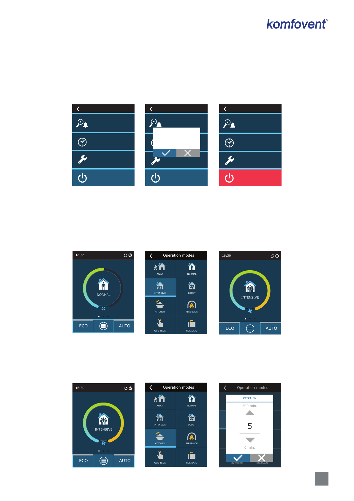
3.1.2. Turning on
The unit must be switched on to operate by a selected ventilation mode, schedule or air quality.
To turn on your air handling unit:
1. Press the ON/OFF button in the centre of the home screen.
2. Conrm the message that appears.
3. A symbol will appear in the centre of the home screen indicating an operating mode which will start soon.
16:30
IŠJUNGTA
ECO AUTO
TURN ON?
16:30
NORMAL
ECO AUTO
16:30
OFF
ECO AUTO
11
UAB KOMFOVENT we reserve the right to make changes without prior notice
C6M_GUIDE2-19-04
3.1.3. Turning o
If you want your device to stop working, regardless the operation schedule and other functions, you can turn it o.
To turn o the device:
1. Press “Menu” button at the bottom of the home screen.
2. Press the ON/OFF button at the bottom of the menu window.
3. Conrm the message that appears.
4. Press a return icon at the top of the window to return to the main screen.
Overview
Scheduling
TURN OFF
Settings
Menu
Overview
Planavimas
TURN OFF
Settings
Menu
TURN OFF?
Overview
Scheduling
TURN ON
Settings
Menu
3.1.4. Mode change
To turn on a standard ventilation mode:
1. Press an icon indicating the current operation mode in the middle of the home screen.
2. Select and press a desired operation mode.
3. An icon for the selected operation mode appears in the middle of the home screen.
16:30
NORMAL
ECO AUTO
INTENSIVE
NORMALAWAY
BOOST
HOLIDAYS
KITCHEN
OVERRIDE
FIREPLACE
Operation modes
16:30
INTENSIVE
ECO AUTO
To turn on a special ventilation mode:
1. Press an icon indicating the current operation mode in the middle of the home screen.
2. Select and press a desired special operation mode.
3. Use the arrows to select desired operation duration and press to conrm.
4. Press the return icon at the top of the screen to return to the home screen.
16:30
INTENSIVE
ECO AUTO
INTENSIVE
NORMALAWAY
BOOST
HOLIDAYS
KITCHEN
OVERRIDE
FIREPLACE
Operation modes
INTENSYVUS
NORMALUSMINIMALUS
MAKSIMALUS
HOLIDAYS
VIRTUVĖ
OVERRIDE
ŽIDINYS
Operation modes
KITCHEN
5
0 min.
300 min.
12 UAB KOMFOVENT we reserve the right to make changes without prior notice
C6M_GUIDE2-19-04
EN
When operating in a special mode, air ow is maintained by CAV method, regardless the selected air ow control method.
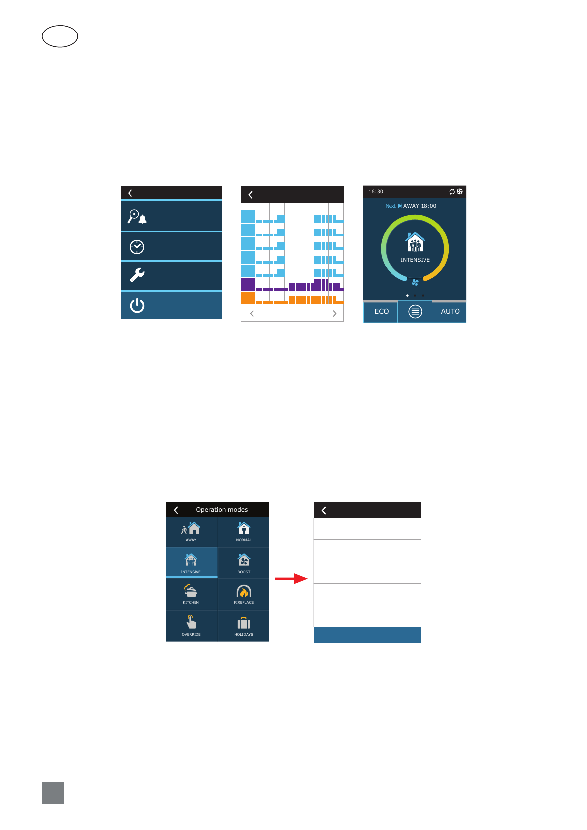
To activate ventilation by a weekly schedule1:
1. Press “Menu” button at the bottom of the home screen.
2. Press “Planning” button in the menu window.
3. Use the arrows at the bottom of the window to select a desired weekly schedule.
4. Press a return icon at the top of the window twice to return to the home screen.
5. Press AUTO button to activate scheduled ventilation.
6. Information about upcoming changes in the schedule is displayed at the top of the screen.
Overview
Scheduling
TURN OFF
Settings
Menu Scheduling
WORKING WEEK
0 4 8 12 16 20 24
Mo
Tu
We
Th
Fr
Sa
Su
16:30
INTENSIVE
ECO АUTO
AWAY 18:00Next
3.1.5. Air quantity and temperature settings
You can set air ow for supply and exhaust air, desired temperature and turn o/on an electric heater for each ventilation
mode. If turned o, the heater will not turn on even when the desired temperature is not reached. If turned on, the heater
will operate only when a heat exchanger alone cannot reach the set temperature.
To change the ventilation mode settings:
1. Press an icon indicating the current operation mode in the middle of the home screen.
2. Press a desired mode button and hold it for 5 seconds.
3. Press a parameter you want to change.
4. Use the arrows to select a desired value and press to conrm.
5. Press a return icon at the top of the screen to return to the home screen.
INTENSIVE
NORMALAWAY
BOOST
HOLIDAYS
KITCHEN
OVERRIDE
FIREPLACE
Operation modes
5 s
Supply flow
210 m3/h
Extract flow
210 m3/h
Electric heater
On
Air temperature
20,0 °C
INTENSIVE
Reset settings
1 Ventilation by a weekly schedule is not possible when air quality control function is activated.
13
UAB KOMFOVENT we reserve the right to make changes without prior notice
C6M_GUIDE2-19-04
Tiekiamas srautas
210 m3/h
Šalinamas srautas
210 m3/h
Elektrinis šildytuvas
Įjungta
Oro temperatūra
20,0 °C
INTENSIVE
Reset settings
21,0
5,0 °C
40,0 °C
Air temperature
Tiekiamas srautas
210 m3/h
Šalinamas srautas
210 m3/h
Elektrinis šildytuvas
Įjungta
Oro temperatūra
20,0 °C
INTENSIVE
Reset settings
210
60 m3/h
300 m3/h
Supply flow
INTENSIVE
Reset settings
Electric heater
Off
On
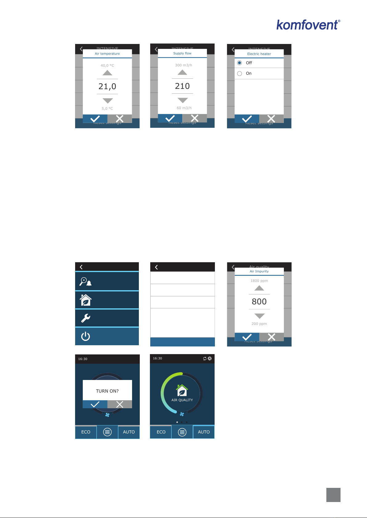
3.1.6. Air quality control mode activation and settings
If air quality sensors are connected to the main board or impurity control/moisture control function is activated (see “Ad-
vanced Settings”), button “Scheduling” appears instead of “Air quality” button. For more information about the air quality
control function see chapter “Air Quality Control Functions”.
To enter desired limits and turn on ventilation by air quality:
1. Press “Menu” button at the bottom of the home screen.
2. Press “Air quality” button.
3. Select a parameter you want to change.
4. Use the arrows to select a desired value and press to conrm.
5. Press a return icon at the top of the screen to return to the home screen.
6. Ventilation by air quality is turned on by pressing AUTO button while the unit is operating in any ventilation mode.
7. If the unit was stopped, pressing AUTO button will call up a message, the conrming of which will activate ventilation
by air quality.
Overview
Air quality
TURN OFF
Settings
Menu
Air Impurity
800 ppm
Air temperature
20,0 °C
Electric heater
On
Air quality
Reset settings
Air quality
Reset settings
Air Impurity
800
200 ppm
1800 ppm
16:30
IŠJUNGTA
ECO AUTO
TURN ON?
16:30
AIR QUALITY
ECO AUTO
14 UAB KOMFOVENT we reserve the right to make changes without prior notice
C6M_GUIDE2-19-04
EN
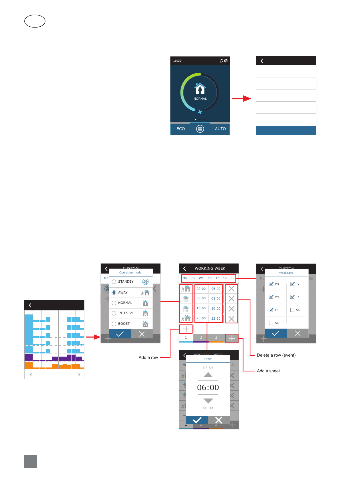
3.1.8. Creating a weekly operation schedule
You can modify ventilation modes, operation time and day for all default operation schedules.
To modify settings of a default schedule:
1. Select a weekly schedule as shown in Chapter “Mode Change”.
2. Press the centre of the schedule window and hold for 5 seconds.
3. By pressing the weekday row you can select which days of the week this schedule sheet is valid for.
4. Pressing the ventilation mode icon on the left will allow selecting a desired ventilation mode.
5. Press time of a specic ventilation mode to change the operation start and end times.
6. Press X on the right to delete a row (ventilation mode and operation start/end times) from a schedule.
7. To add an additional row, press + under the last scheduled row (maximum 5 rows). If the last event ends at 24:00, you
will have to delete it to add a new row.
8. To add another sheet, press + at the bottom of the window (maximum 4 sheets).
Scheduling
WORKING WEEK
0 4 8 12 16 20 24
Mo
Tu
We
Th
Fr
Sa
Su
WORKING WEEK
Mo Tu We Th Fr Sa Su
00:00 06:00
08:00
06:00
20:00
16:00
22:30
20:00
12 3
WORKING WEEK
Mo Tu We Th Fr Sa Su
00:00 06:00
08:00
06:00
20:00
16:00
22:30
20:00
12 3
Start
06:00
00:00
07:59
CUSTOM
Mo TU We Th Fr Ša Su
00:00 00:01
Operation mode
STANDBY
AWAY
NORMAL
INTESIVE
BOOST
CUSTOM
Mo Tu We Th Fr Sa Su
Weekdays
Tu
Th
Sa
Mo
We
Fr
Su
Delete a row (event)
Add a sheet
Add a row
5 s
3.1.7. ECO mode activation and settings
ECO mode may be activated in any ventilation mode
by pressing ECO button at the bottom of the home screen.
For more information about the ECO mode see chapter “Air
Quality Control Functions”.
To change the ECO mode settings:
1. Press ECO button and hold it for 5 seconds.
2. Press a parameter you want to change.
3. Select a desired option or set a desired value using
arrows.
4. Conrm your selection.
5. Press a return icon at the top of the window to re-
turn to the home screen.
16:30
NORMAL
ECO AUTO
5 s
Heater blocking
On
Cooler blocking
On
Free cooling
On
Min. supply air temperature
15,0 °C
Max. supply air temperature
25,0 °C
ECO
Reset settings

15
UAB KOMFOVENT we reserve the right to make changes without prior notice
C6M_GUIDE2-19-04
To create a weekly operation schedule:
1. Select a weekly schedule “My week” as shown in Chapter “Mode Change”.
2. Press the centre of the schedule window and hold for 5 seconds.
3. Press the weekday row to select which days of the week this schedule sheet is valid for.
4. Press + symbol and add a new row.
5. Press the ventilation mode icon on the left to select a desired ventilation mode. There is no need to include a STAND-
BY mode in the schedule for intervals when the unit will not operate. The unit will be stopped during any intervals for
which no ventilation mode is assigned.
6. Set the start and end time for a ventilation mode. If you need 24-hour ventilation, set the start time for 0:00 and the
end time for 24:00.
7. To add an additional row, press + under the last scheduled row (maximum 5 rows). If the last event ends at 24:00, you
will have to delete it to add a new row.
8. To add another sheet, press + at the bottom of the window (maximum 4 sheets).
Scheduling
CUSTOM
0 4 8 12 16 20 24
Mo
Tu
We
Th
Fr
Sa
Su
CUSTOM
Mo Tu We Th Fr Sa Su
CUSTOM
Mo Tu We Th Fr Sa Su
Weekdays
Tu
Th
Sa
Mo
We
Fr
Su
5 s
CUSTOM
Mo Tu We Th Fr Sa Su
CUSTOM
Mo Tu We Th Fr Sa Su
00:00 00:01
1
CUSTOM
Mo Tu We Th Fr Sa Su
00:00 00:01
Operation mode
STANDBY
AWAY
NORMAL
INTESIVE
BOOST
CUSTOM
Mo Tu We Th Fr Sa Su
00:00 00:01
Start
06:00
00:00
23:59

16 UAB KOMFOVENT we reserve the right to make changes without prior notice
C6M_GUIDE2-19-04
EN
3.1.9. Main settings
In the menu point SETTINGS you can modify the main user interface settings:
Overview
Scheduling
TURN OFF
Settings
Menu
Language
English
Flow units
m3/h
Panel lock
None
Panel sound
Time/Date
Screen saver
On
Settings
Language – set a desired control panel language using arrows.
Flow measurement units – select units for air ow measurement.
Settings
Language
English
Русский
Lietuvių
Settings
Flow units
m3/h
l/s
Screen saver – turn the screen saver on/o. Screen saver activates when a control panel is not used for longer than 1 min.
You may select brightness of a screen saver, as well as settings and the order in which they are displayed. If a screen saver is
deactivated, the control panel display turns o if not used for longer than 1 min. Tap a screen to wake-up.
Panel lock – partial or full panel lock is available. Partial lock allows turning on/o an air handling unit and selecting
desired ventilation mode but does not allow any ventilation settings to be changed. Full panel lock prevents the user from
using the control panel. To unlock the panel, you have to enter your four-digit PIN code. When the lock is on, the panel will
lock every time the screen saver is activated.
Activate
Brightness
50%
Row 2
Panel temperature
Row 3
Panel humidity
Row 1
Time
Screen saver
Kalba
Lietuvių
Srauto vienetai
m3/h
Pulto užraktas
Nėra
Pulto garsas
Ekrano užsklanda
Įjungta
Settings
Panel lock
None
Partial
Full

17
UAB KOMFOVENT we reserve the right to make changes without prior notice
C6M_GUIDE2-19-04
Panel sound – turning on/o touch and message sounds.
Time/Date – setting the time and date that are used for a weekly operation schedule or other functions.
Touch sound
Click
Alarms sound
On
Panel sound
Time
14:02
Month/Day
12/10
Year
2018
Time/Date
3.1.10. Advanced settings
To access the advanced settings, press and hold the SETTINGS button for 5 seconds.
5 s
Overview
Scheduling
TURN OFF
Settings
Menu
Temperature control
Flow control
Control sequence
Connectivity
Air quality control
Advanced settings
1/ 2
Clean filters calibration
Reset settings
Advanced settings
2/ 2
Temperature control – select a method for temperature control (see Chapter 2.2).
Temperature control
Supply
Temperature control
Temperatūros palaikymas
Tiekimas
Temperature control
Temperature control
Supply
Extract
Room
Balance
18 UAB KOMFOVENT we reserve the right to make changes without prior notice
C6M_GUIDE2-19-04
EN
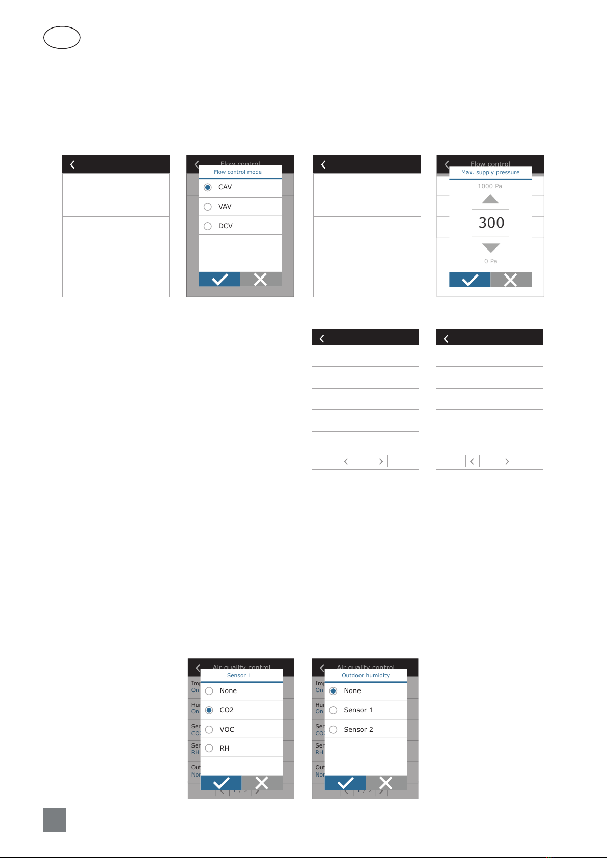
Flow control – select a method for air ow control (see Chapter 2.1). Selected CAV or DCV air ow control allows additional
corrections of supply and extract air measurements, when the measured air volume does not match the actual one. This may
also be due to design features of the duct system, for example, wrong diameter ducts, excessive number branches or elbows,
or installation without following the installation recommendations. When a VAV mode is selected, a measurement range
of pressure sensors connected to the main board must be additionally entered (see “Installation Manual”), i.e. maximum
pressure Pa that the sensor is measuring by 10V output (measurement range is specied in the VAV sensor manual).
Flow control mode
CAV
Supply flow correction
0 m3/h
Extract flow correction
0 m3/h
Flow control
Flow control
Flow control mode
CAV
VAV
DCV
Flow control mode
VAV
Max. supply pressure
300 Pa
Max. extract pressure
300 Pa
Flow control
Srauto palaikymo režimas
VAV
Maks. tiekiamo oro slėgis
300 Pa
Maks. šalinamo oro slėgis
300 Pa
Flow control
Max. supply pressure
300
0 Pa
1000 Pa
• Impurity control – turning on/o an impurity control function. At least one CO2 or VOC sensor must be connected to the
controller board to activate this function (see Chapter 2.6.2.). If ventilation by a weekly schedule is required, this function
must be turned o.
• Humidity control – turning on/o a humidity control function. Humidity control function requires a humidity sensor. If
no humidity sensor is connected to the controller board, sensor integrated in a control panel will be used for this purpose
(see Chapter 2.6.2.).
• Sensor 1 – specify the type of the sensor connected to a terminal B8 (see “Installation Manual”). If this sensor is not
available, select “None”.
• Sensor 2 – specify the type of the sensor connected to a terminal B9 (see “Installation Manual”). If this sensor is not
available, select “None”.
• Outdoor humidity – this option appears when one of the sensors is of RH type (humidity sensor). If any of the connected
sensors are installed in the outdoor air ow, specify which one. If none of the installed humidity sensors measure the
outside humidity, select “None”.
Air quality control
1/ 2
Impurity control
On
Humidity control
On
Sensor 1
CO2
Sensor 2
RH
Outdoor humidity
None
Sensor 1
None
CO2
VOC
RH
Air quality control
1/ 2
Impurity control
On
Humidity control
On
Sensor 1
CO2
Sensor 2
RH
Outdoor humidity
None
Outdoor humidity
None
Sensor 1
Sensor 2
Air quality control – here you can activate and set-up
air quality control which will be used in AUTO mode (see
Chapter 2.6.2).
Air quality control
1/ 2
Impurity control
On
Humidity control
On
Sensor 1
CO2
Sensor 2
RH
Outdoor humidity
None
2/ 2
Air quality control
Minimum intensivity
0 %
Maximum intensivity
70 %
Check period
2h

19
UAB KOMFOVENT we reserve the right to make changes without prior notice
C6M_GUIDE2-19-04
• Minimum intensity – select ventilation intensity at which the unit will operate when air quality (impurity or humidity) is
good. If 0% is selected, the unit will stop when air impurity level is low.
• Maximum intensity – select ventilation intensity limit, under which the unit will operate when air quality (impurity or
humidity) exceeds a dened value.
• Check period – specify how often the unit shall turn on to check air quality, when minimum intensity is set to 0%.
Control sequence – here you can activate additionally connected duct-mounted heating or cooling devices (see
“Installation Manual”) that will operate only when a heat exchanger or electrical heater alone cannot reach a desired
temperature.
Control sequence
1/ 2
Stage 1
Electric heater
Stage 2
External coil
Stage 3
None
External coil type
Cold water
Icing protection
On
2/ 2
Control sequence
Indoor humidity
Auto
Allow dehumidifying with cooling
Off
Numbers indicate the order of activation. All units have an integrated electrical heater, therefore it is factory-assigned as
Stage 1. You can also assign an “external coil” (duct-mounted water heater/cooler) or an “external DX unit” (direct evaporation
heat exchanger) as a stage. If an external coil is selected, you also must specify its type: “Hot water” (used for heating), “Cold
water” (used for cooling) or AUTO (both for heating and cooling). If AUTO type is selected, heating or cooling operations are
decided by an external signal connected to the controller board terminals (see “Installation Manual”). If additional heating/
cooling devices are not available, you do not want to use them or an electrical heater, select “None”.
Stage 1
None
Electric heater
External coil
External DX unit
Control sequence
1/ 2
Stage 1
Electric heater
Stage 2
External coil
Stage 3
None
External coil type
Cold water
Icing protection
On
External coil type
Hot water
Cold water
Auto
If you turn o an electric heater and do not activate a duct-mounted heater, the desired air
temperature may not be reached when the outside air is cold.

20 UAB KOMFOVENT we reserve the right to make changes without prior notice
C6M_GUIDE2-19-04
EN
• Antifreeze protection – this setting is only available in units with counter-ow plate heat exchangers. These units are
equipped with electric pre-heaters which heat the outdoor air and protect a heat exchanger from freezing. Power of a
heater is regulated according the outside air temperature, indoor humidity and actual ow of ventilated air. Integrated
electric pre-heater operates on demand only when there is a risk of heat exchanger to freeze. Under very low indoor
humidity conditions, it is unlikely that the heat exchanger would freeze even at very low outdoor temperatures.
The following antifreeze protection settings are available:
ON – automatic protection with an integrated pre-heater is activated by default.
OFF – protection may be switched o, but the unit will also be turned o when the outside air temperature drops below
-4 °C.
External coil – when an external heater, connected to AUX terminals of the main board, is used instead of an integrated
pre-heater (see “Installation Manual”).
• Indoor humidity – this setting is necessary for estimating power of a pre-heater.
Possible settings:
Auto – indoor humidity is set automatically using an integrated humidity sensor and/or external humidity sensors
connected to B8 and B9 terminals of the controller (see “Installation Manual”).
10...90 % – setting a xed indoor humidity value is possible when a control panel is installed in inappropriate location (or
is not used) and no outside humidity sensors are connected.
Control sequence
1/ 2
Stage 1
Electric heater
Stage 2
External coil
Stage 3
None
External coil type
Cold water
Icing protection
On
Off
On
External coil
Icing protection
2/ 2
Control sequence
Indoor humidity
Auto
Allow dehumidifying with cooling
Off
Indoor humidity
Auto
10 %RH
90 %RH
Wrong value of indoor humidity may cause antifreeze protection to malfunction and a counter-ow
heat exchanger to freeze.
• Allow dehumidication with cooling –this setting must be enabled to use a DX unit or duct-mounted water cooler to
dehumidify the supply air. An option to enter a value for desired humidity will appear in the settings of standard ventila-
tion modes (see Chapter 2.6.2).
Connectivity – you can congure your PC network settings for remote use via web browser: IP address and subnet mask.
You may also change other network parameters, if necessary: Gateway and BACnet ID. DHCP option automatically assigns a
free IP address in the local network (do not use this option if you connect your computer directly to the unit).
Connectivity
IP address
192. 168. 0. 60
Subnet mask
255. 255. 0. 0
Gateway
192. 168. 0. 1
BACnet ID
60
DHCP
Other manuals for DOMEKT series
4
This manual suits for next models
21
Table of contents
Other Komfovent Fan manuals

Komfovent
Komfovent Verso Pro 2 Series User manual

Komfovent
Komfovent DOMEKT RHP 400 U-2,2/1.4 User manual

Komfovent
Komfovent KOMPAKT REGO Series User manual
-B-AC/EC Manual")
Komfovent
Komfovent DOMEKT ReCU 300/350/450VE(W)-B-AC/EC Manual

Komfovent
Komfovent DOMEKT ReGO 200VEW-BK User manual

Komfovent
Komfovent DOMEKT C8 automation User manual

Komfovent
Komfovent DOMEKT ReGO 200VE-B Manual

Komfovent
Komfovent VERSO Pro S Manual

Komfovent
Komfovent VERSO Pro S Manual


