10
The gearcase is not vented. The Relialube system
requires no relocation or installation of breather
vents for any approved mounting position, although
the oil fill quantity must be changed for mounting
positions other than the factory-standard K1/L1/S1
and grease fittings are required on output shaft up
and down versions. Reducers should be ordered for
the specific mounting position desired.
MAINTENANCE
The MASTER ComboGear reducer requires
little maintenance, but an occasional inspection to
check for hardware security, mounting integrity,
leakage and general overall condition is good
standard practice.
Seals are normal wear items and may require
periodic replacement.
LUBRICATION – GENERAL
The standard lubricant is Mobil SHC 634, which is
suitable for –10°F to +100°F ambient.
For low temperature operation, Mobil SHC 629 is
suitable for –30°F to +60°F ambient.
For those food processing installations requiring
USDA Class AA and H1 approvals, use Chevron
FM460X which is suitable for use from +15°F to
110°F.
Stock units are factory filled with Mobil SHC 634 for
the K1/L1/S1 mounting position unless specified at order.
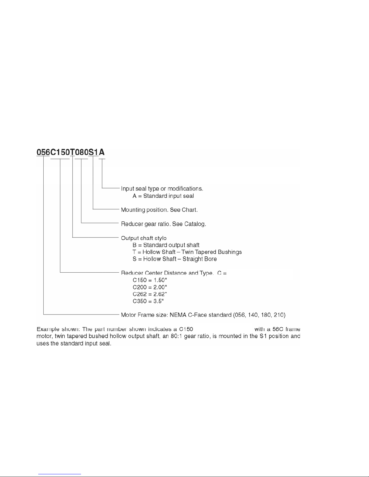
LUBRICATION – OIL FILL LEVELS
To change from one mounting position to another,
you MUST correct the oil quantity so the total oil in
the gearcase is as listed below. Failure to follow
these instructions will void warrantee. Oil is added to
the prescribed level with the gearcase sitting in the
K1/L1/S1 position, before the reducer is mounted in
the desired position.
NOTE: Vertical output shaft (up or down)
conversions require a new upper bearing housing
equipped with grease fittings. Consult Renewal
Parts.
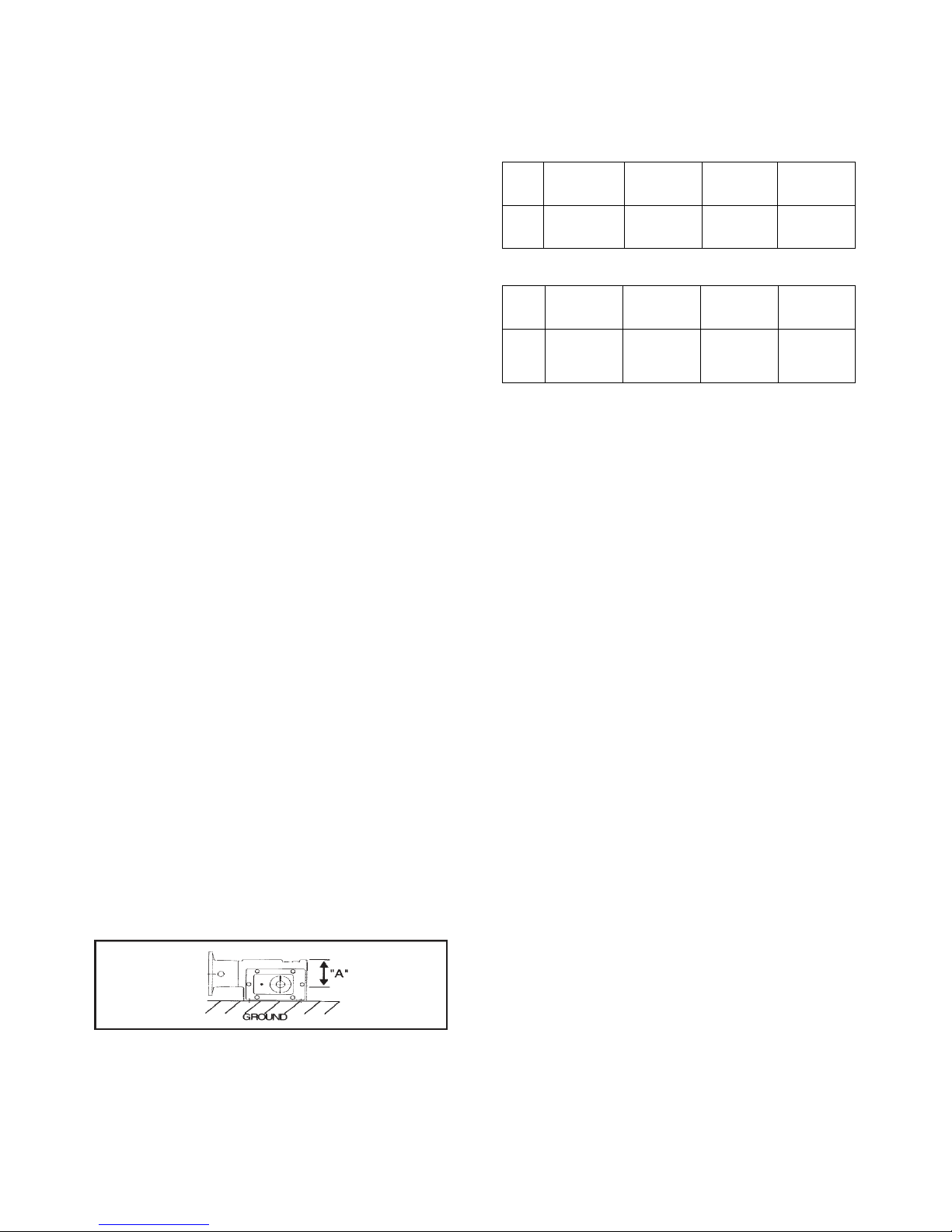
Dimension “A” is measured with a dipstick inserted
into the tapped fill hole from the machined top of the
gearcase to the oil level with the gearbox set level
on the ground.
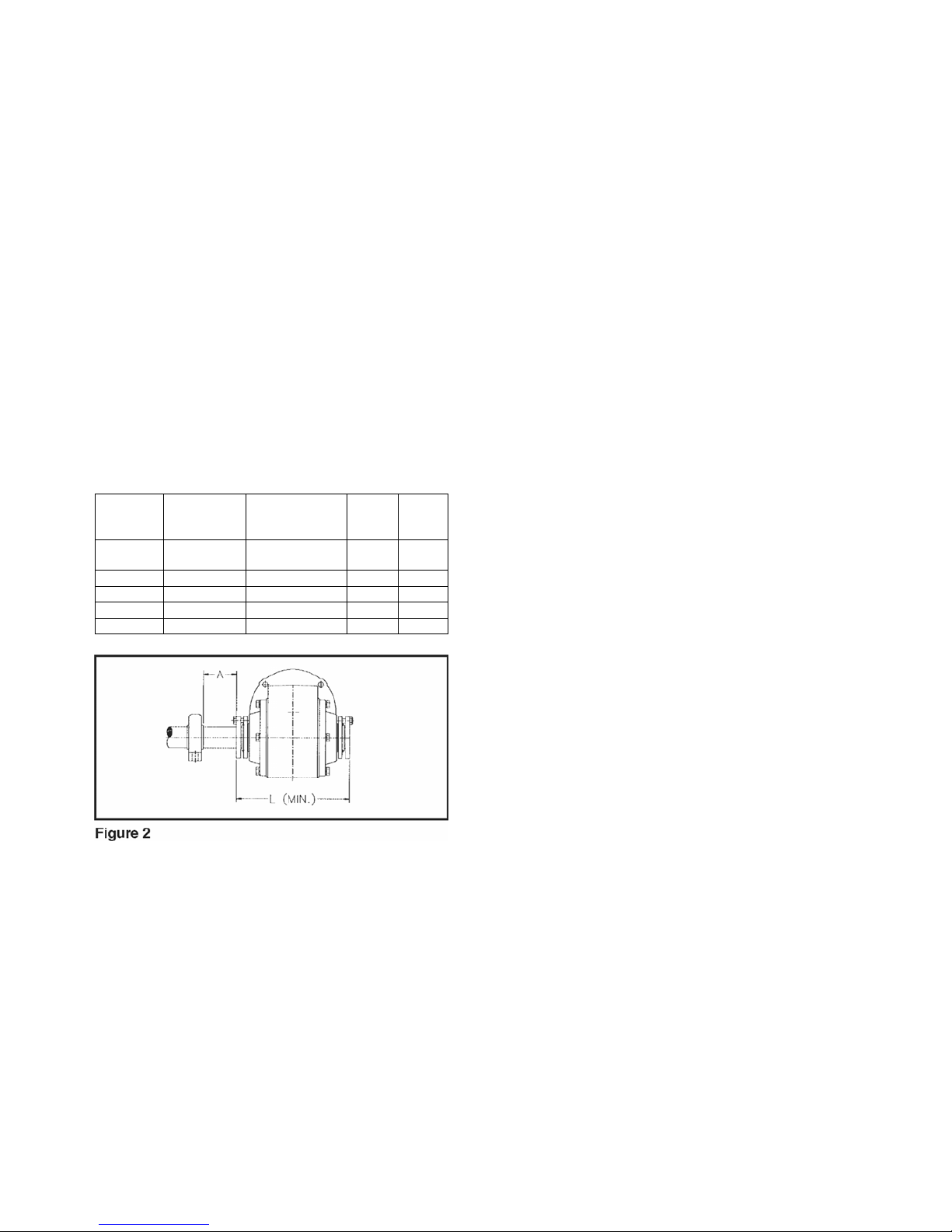
Approximate oil volumes (fluid ounces) by case size
and assembly. Divide ounce quantities by 16 for
volumes in pints.
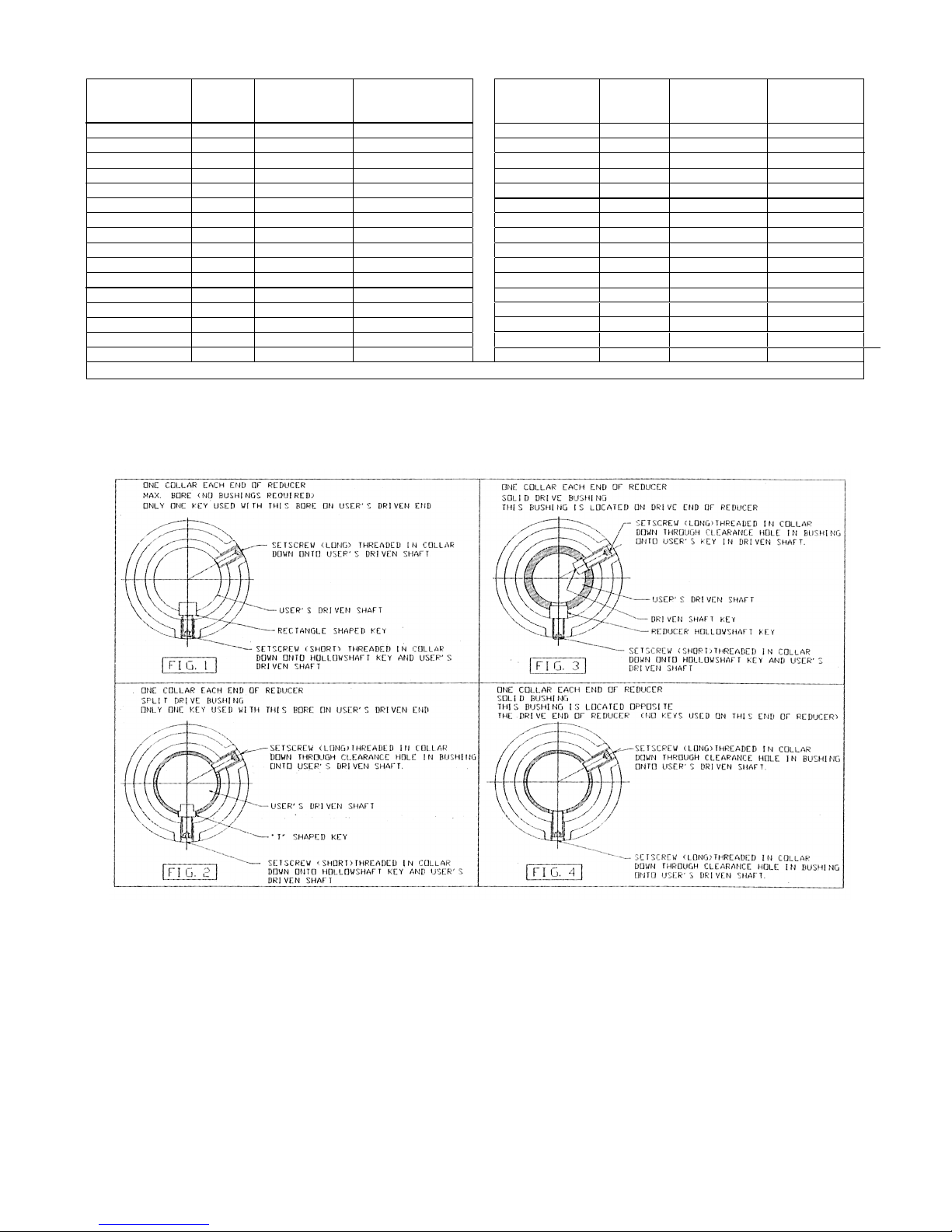
HOLLOW (TAPERED OR STRAIGHT BORE) OUTPUT SHAFT
Assm. S1 Dist. S2 S4 S5
H4 “A” H1 “A” H3 “A” H5 “A”
B2 (in.) B3 (in.) B1 (in.) B5 (in.)
Size
C150 24 oz. 2¾” 27 oz. 2¼" 27 oz. 2¼" 43 oz. 1½"
1
C200 40 oz. 3¾" 44 oz. 3¼" 44 oz. 3¼" 60 oz. 2 /8"
C262 64 oz. 5¾" 112 oz. 2¾" 112 oz. 2¾" 112 oz. 2¾"
C350 168 oz. 6" 235 oz. 4" 235 oz. 4" 256 oz. 3
3/ "
8
SOLID OUTPUT SHAFT
Assm. L1 L4 K4 L5
K1 Dist K2 L2 K5
B2 “A” B1 “A” B3 “A” B5 “A”
H4 (in.) H1 (in.) H3 (in.) H5 (in.)
Size
C150 27 oz. 2¾" 32 oz. 1¾" 52 oz. 3/4" 48 oz. 3/4"
C200 40 oz. 3¾" 44 oz. 3" 68 oz. 1½" 68 oz. 1½"
C262 83 oz. 5¼" 96 oz. 33/8” 128 oz. 1¾" 128 oz. 1¾"
C350 168 oz. 6" 235 oz. 4½" 312 oz. 1½" 256 oz. 4"
LUBRICATION – VERTICAL
OUTPUT SHAFT MOUNTINGS
Vertical output shaft assemblies such as
K2/L2/K4/L4/S2/ S4 require periodic lubrication of
the reducer bearings that are out of the oil splash.
These units are equipped with grease fittings on the
upper intermediate and output shaft bearings.
Lubrication frequency is 2 pumps from a hand
grease gun every 6 months or 2000 hours operation.
Do not overgrease. The recommended lubricant is
Shell Alvania #2.
NOTE: Units shipped from the factory for vertical
output shaft mounting positions have grease fittings
wired to plugs in the bearing housings. This prevents
oil leakage through the fittings. Plugs must be
replaced with grease fittings before use.
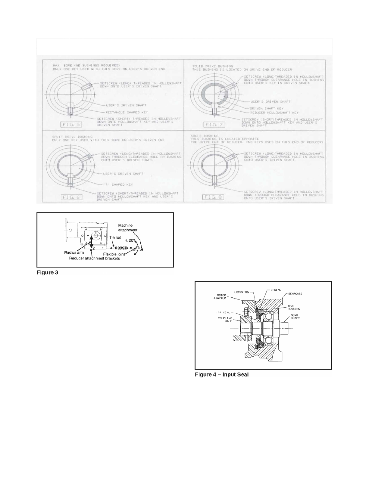
INPUT SEAL REPLACEMENT
The input seal on the all-position RELIALUBE
design is considered a normal wear item with a finite
life. If necessary, the input seal is easily replaced.
Refer to assembly drawings.
1. Stop and lock out the motor.
2. Remove four bolts attaching the motor to the motor
adapter. Remove the motor. The motor coupling half
will come off with the motor.
3. Remove four bolts attaching the motor adapter to
the reducer gearcase. Remove adapter. Do not
remove the reducer-side input coupling half yet.
Remove the large retaining ring from the bore of the
input of the reducer gearcase.
4. Use two prybars, spaced 180º, behind the input
coupling against the gearcase face and gently pry the
input shaft out of the gearcase. The input seal housing
will come out with it. It is not normally necessary to
completely remove the input shaft from the gearcase.