Kongskilde KDC 8000 User manual

KDC 8000
Combi-cleaner
Manual
Brugsanvisning

2
GB
This operators manual applies to the
Kongskilde combi cleaner type KDC 8000
Preface:
This users manual has been prepared in accord-
ance with EU-directive 2006/42/EC (Machinery
Directive).
Marking:
See enclosed Declaration of Conformity.
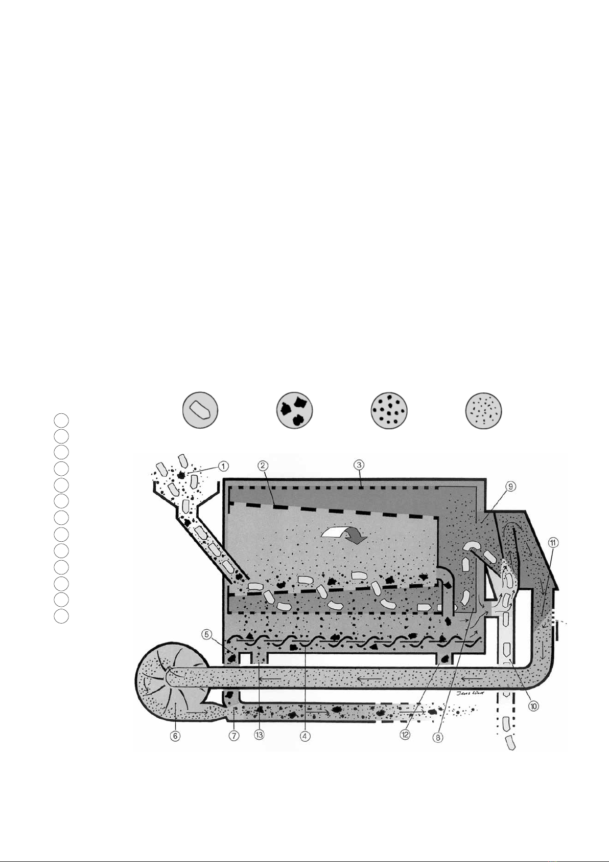
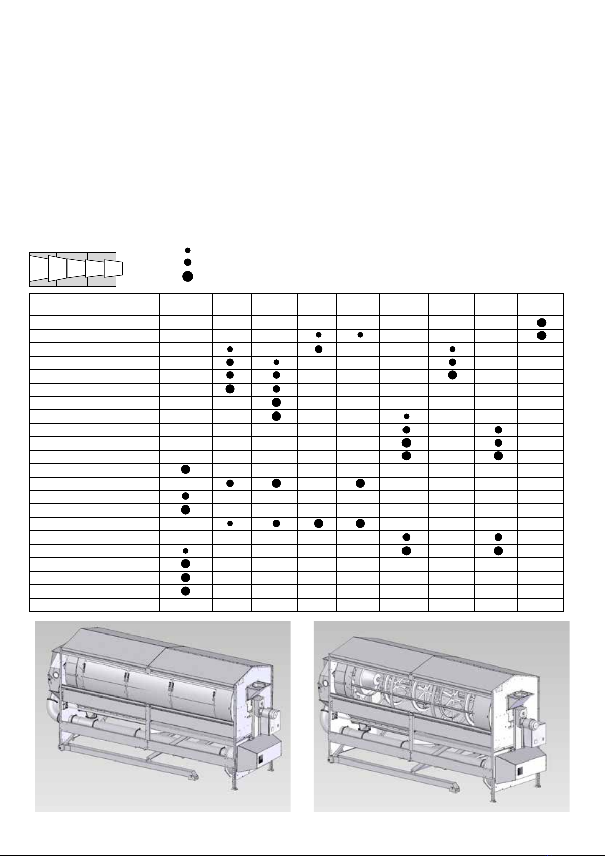
Description:
KDC 8000 is a combined screen- and aspiration
cleaner, designed for separation of grain and
impurities. The rotating screens are driven by an
electrical gear motor, and the cleaned crop can be
conveyed by the aspirator to a transport system.
The impurities are blown away together with the
aspirator air, and should be separated through a
cyclone and collected.
The cleaner can be equipped with screens
containing different hole sizes, depending on the
nature of the crop.
Capacity varies depending on the crop to be pro-
cessed, up to 80 tonnes per hour in easy oating
crop, depending on the requirements towards purity
of the crop.
The cleaner is primarily designed to be used for
pre cleaning of grain, corn, canola, sun ower
and beans from larger and smaller impurities.
Furthermore, the cleaner can be used for grading of
malting barley.
The cleaner should be feed continuously.
Typical application:
The combi cleaner has been designed for the pre-
cleaning of wheat, barley, rye, oats, rapeseed,
maize, peas, soybeans and sunower for larger and
minor impurities.
Warning notes:
• Take care that all guards are in correct position
and xed during operation.
• Always stop the combi cleaner prior to repair
and maintenance and avoid unintentional start of
the combi cleaner. Lock e.g. the on/off switch on
the built in control box or install a safety switch
mounted in the electrical installations to avoid
unintentional start of the cleaner.
• Only turn the screen drum manually when re-
placing the screens. Never turn the screen drum
by switching on the gear motor, when replacing
the screens.
• Use always gloves when replacing screens. The
screens may have sharp edges.
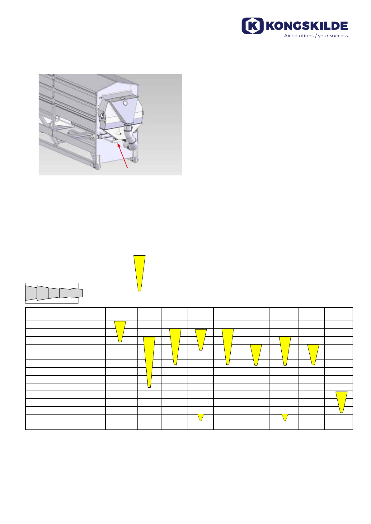
• Never put the hand in the outlet of the trough
auger.
• Never leave the outlet open, while the cleaner is
in operation. Connect the outlet to a container or
to a min. 800 mm long OK200 pipe, to prevent
access to the rotating parts.
• Never put your hand into the inlet or outlet open-
ing of the blower during operation.
• All electrical installations must be effected ac-
cording to the current legislation.
• In case of abnormal vibrations or noise, stop the
cleaner immediately and investigate. If in doubt,
call in expert assistance for repair and mainte-
nance.
• Mount the cleaner on a solid and plane base, to
avoid the cleaner tipping over.
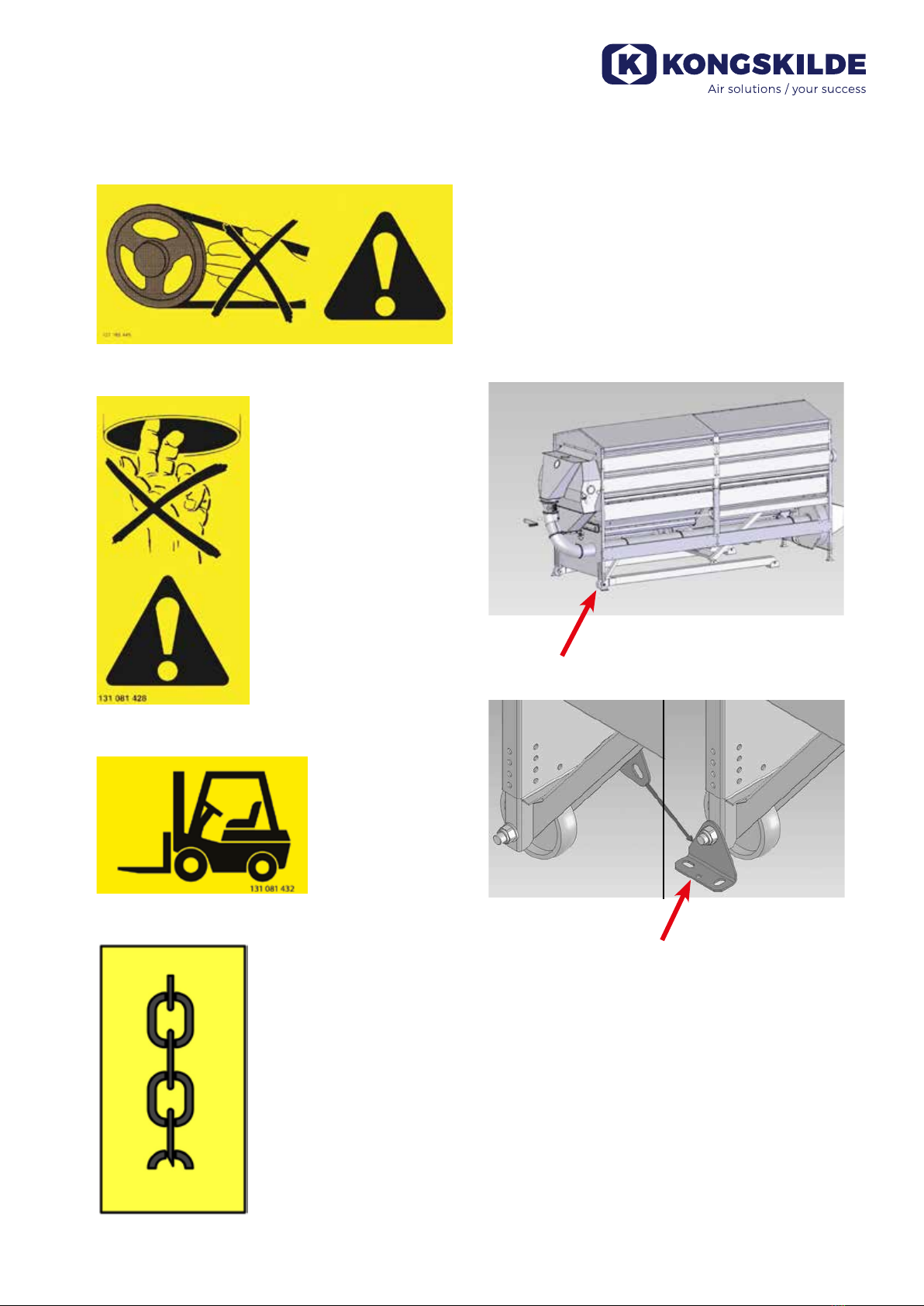
• If the cleaner is to be moved, use the four lift-
ing points in the corners (marked with the chain
symbol) or use a forklift or the like grabbing in
the rails under the base frame of the cleaner
at the indicated points. The forks must be long
enough to lift in both sides of the cleaner.
Warning signs:
Avoid accidents by always following the safety
instructions given in the manual and on the warning
signs placed on the cleaner.
Safety signs without text are used on the machine.
The signs are explained below.
Read carefully the manual
before using the cleaner, and
observe the warning signs on
the cleaner.

3
Floor brackets:
If the cleaner is mounted on a platform or similar,
it is important that the cleaner is secured against
falling down. It is therefore advised to bolt it to the
oor, by means of the two supplied oor brackets.
The oor brackets are attached to the angled brace
at delivery of the cleaner. They can be removed for
attachment onto the transport wheels´ axle. Hereaf-
ter the oor bracket can be bolted onto the oor.
Height adjustment:
The height of the cleaner can be adjusted in both
ends by means of the telescopic legs. Lift the clean-
er above desired height, move bolts to a suitable
hole location, and lower the cleaner. Make sure the
setting leaves the cleaner in a horizontal position.
Take care that the guard for the V-belt transmission
is in correct position and xed during operation.
Never put the hand in the
outlet of the trough auger,
while the cleaner is in
operation.
Location of lifting points for forklift
Location of lifting points
The brackets are attached onto the wheels´ axles
Brackets for fastening the KDC 8000 to the oor

4
Transport brackets:
KDC 8000 is equipped with transport brackets for
the purpose of maneuvering the unit during loading
and unloading, and to protect the machine during
transportation. The transport brackets will also be
Transport bracket back
end, for protection
during transportation
Transport and protection bracket
in the front end.
This cross bar is used to lift
the front end of the cleaner for
example with a fork lift
Lifting bars for forklift
NB - Ensure proper
free space when ma-
nouvering the forklift
Wheels
Special bracket is supplied
together with the KDC 8000
to use on the forks on the
forklift, when moving it during
transportation.
On forklifts having hydraulics to move the forks
sideways, the bracket is put on the end of the
forks, and the forks are pushed together to hold the
bracket. The hydraulics is normally strong enough
to hold the bracket during transportation of KDC
8000.
used for transportation on level surfaces.
The cleaner is having small wheels in the back
end for transportation in the length direction. This
can be useful when loading the unit into or out of a
container.

5
If the fork lift is not having hydraulics to operate the
forks, the chain is used to hold the bracket in such
a way that it is not pulled off the forks when moving
backwards.
Lifting and moving of KDC 8000 with forklift
When the cleaner is installed in the nal set up,
the transport brackets can be removed.
KDC 8000 without transport brackets mounted

6
Principle of operation:
Unclean grain ows into the conical shaped inner
screen. The inner screen hole diameter allows the
grain to pass through, keeping the large impurities
back.
Having passed through the inner screen the grain
falls onto the outer cylindrically shaped screen.
Its slot dimensions are designed to keep the grain
back and allow light impurities to fall through. The
drum containing the inner and outer screens rotates
at approx. 22 rpm.
The combi cleaner is installed at an angle of inclina-
tion of approx. 9° to the rear, causing the crop to
move across the screens as a result of the rotary
movement of the drum.
After the mechanical cleaning, the crop is carried
to an aspiration cleaner where light impurities and
dust are extracted.
The impurities from both screens are collected in a
trough at the bottom of the unit.
At the bottom of the trough is an auger carrying the
trash to the front of the unit where the screenings
may either be discharged through a separate grav-
ity outlet (e.g. used when grading malting barley)
or delivered into the trash blow line by the combi
cleaner's fan and discharged together with the light
impurities.
Oversized impurities separated by inner screen can
also be discharged separately.
Crop Large impurities Small impurities Light impurities
1 Intake
2 Inner screen
3 Outer screen
4 Auger
5 Screenings outlet
6 Fan
7 Venturi
8 Scoop elevating section
9 Aspiration chamber
10 Outlet, cleaned grain
11 Air bleed
12 Outlet from inner screen
13 Outlet for small grain,
used e.g. when grading
malting barley

7
Installation:
The cleaner may be advantageously installed to
allow crop passage immediately after intake and
before discharge.
Location
Place the cleaner so as to allow space beside the
unit for necessary adjustments.
Do not forget to provide space for screen replace-
ment, i.e. about 1.5 m beside the unit. Screen re-
placement is most easily done from the right-hand
side of the combi cleaner (viewed from the inlet
end).
Direction of rotation
Wiring should be made for counter-clockwise direc-
tion of rotation of screen drum, fan and trough au-
ger (viewed from the inlet end).
Wiring diagram for the cleaner is placed in the con-
trol box.
Pipeline for blower
The blower pipeline should be of the Kongskilde
OK200 dimension. It is recommended to use as few
bends as possible and a cyclone at the end of the
pipeline.
At a commonly occurring content of impurities in the
crop, the fan is powerful enough to blow the trash
approx. 20 m (including 4 meters vertical length,
two bends and one cyclone).
If to much fan power is applied to conveying, this
will reduce the air ow and, accordingly, the
cleaning efciency of the aspiration cleaner. If ad-
ditional conveying length is required, an extra fan
may be inserted.
Separation of screenings
The screenings may either be discharged through
a separate gravity outlet or delivered into the trash
blow line (A) and discharged together with the light
impurities.
1,5 m
90°
90°
4 m
Cyclone
OK200 pipeline
BC
A

8
Impurities separated by screens and aspirator
discharged into the trash blow line
Mount the covering plate in the outlet (B) and (C) of
the trough auger.
Impurities separated by screens and aspirator
discharged separately
Remove the covering plate from the outlet (B) of
the trough auger. If desired a shutter may be tted
instead of the covering plate.
Oversized impurities separated by inner screen can
also be discharged separately.
Oversized impurities separated by inner screen
discharged separately
Remove the covering plate from the outlet (C) of
the trough auger. If desired a shutter may be tted
instead of the covering plate.
Capacity:
Maximum capacity of the combi cleaner for pre-
cleaning of grain is approx. 80 tons/hour.
Generally, the capacity will depend on the required
cleaning efciency - the smaller the load on the
screens, the better the separation of impurities.
The conveying system should therefore be de-
signed to allow adjustment of the material supply
to the cleaner, to obtain the desired cleaning ef-
ciency.
General advice concerning capacity and selec-
tion of screens:
The inner screen separates the large impurities
from the crop. The main ow of crop has to pass
through the inner screen. Selecting screen with
small hole size compared to the kernel size gives
the most efcient cleaning, but reduces capac-
ity. Selecting screen with large holes compared to
kernel size gives capacity but reduce cleaning ef-
ciency. If too much crop is feed into the KDC 8000,
good kernels will be discharged together with the
impurities.
To reach max. capacity it is then necessary to
use screens with large enough holes to allow the
kernels to pass through fast enough. On the outer
screen small impurities and small kernels are sepa-
rated from the crop. For pre cleaning, there is no
limitation in capacity in relation to screen selection.
For size separation of kernels on the outer screen
approx. 10 – 20% of the capacity rated for pre
cleaning can be obtained.
Inclination:
In case the cleaner should be used for pre cleaning,
it is advised to adjust the inclination to approx. 9° to
the rear.
At an inclination of approx. 4.5° the inner screen is
horizontal at the bottom. The inclination must there-
fore never be less than 4.5° as the inner screen
should either be horizontal or incline towards the
outlet end.
The angle of inclination should normally never
exceed 12°. The pipe connections for the cleaner
should therefore minimum allow adjustment of the
inclination between 8° and 12°, when used for pre
cleaning. If the cleaner is also going to be used for
separation inclination may vary from 5° - 12°.
Connect, for instance a exible steel hose to the
inlet and the fan discharge opening (Kongskilde
product no. 122 050 156).
For adjustment of the working angle use the gradu-
ated scale on the side of the cleaner.
Set the arrow to the desired number of degrees.
Now raise the inlet end of the cleaner using the
crank located at the outlet end of the cleaner until
the spirit level indicates that the arrow is horizontal.
9°

9
Screen for inner drum
On the inner drum, the crop is to pass through the
screen and the large impurities be arrested.
Screens with a small hole diameter will therefore
ensure optimum separation of large impurities; at
the same time, however, the capacity will be re-
duced.
A large hole diameter, on the other hand, will result
in a high capacity and reduced separation of large
impurities.
As standard we recommend the same hole diam-
eter on the rst two sections. However, in the event
of low capacities a better separating will often be
obtained by using a smaller hole diameter on the
1st and 2nd section. Still, the greater part of the
crop is to pass through the rst 3 sections of the
inner screen.
Screen sizes:
To obtain optimal efciency, it is important to use
screens of correct slot/hole dimensions.
A range of screen sizes suitable for ordinary crops
is available.
9°
Crank for adjustment of inclination
Inner screen
Screen choice
Screen sections
Screen Perforation in Sections (mm)
1 – 2 – 3 – 4 - 5
Maize
(Corn)
Wheat Barley Oat Rye Soya beans Sun ower Peas Rape seed
Ø17/Ø17/Ø15/Ø15/Ø15
Ø15/Ø15/Ø13/Ø13/Ø13
Ø13/Ø13/Ø11/Ø11/Ø11
Ø11/Ø11/Ø9/Ø9/Ø9
Ø9/Ø9/Ø7,4/Ø7,4/Ø7,4
Ø8/Ø8/Ø7,4/Ø7,4/Ø7,4
Ø7,4/Ø7,4/#5,2/#5,2/#5,2
Ø7/ Ø7/#5,2/#5,2/#5,2
Ø6,5/Ø6,5/#5,2/#5,2/#5,2
#5,2/#5,2/Ø4,3/Ø4,3/Ø4,3
Ø4,3/Ø4,3/Ø3,5/Ø3,5/Ø3,5
Ø3,5/Ø3,5/#2,75/#2,75/#2,75
Oblong holes 5 x 20 (all sections)
Oblong holes 10 x 30 (all sections)
Max. capacity
Max. cleaning eff. -
reduced capacity
1 2 3 4 5

10
Screens for outer drum
On the outer drum, the crop passes across the screen
while the small impurities will fall through.
Thus it is the slot dimensions of the outer screen that
determine the size of the impurities arrested.
In selecting your screen you should also consider the
grain size, as a screen with too large slot dimensions will
also separate small-sized grains.
If an outer screen with oblong holes is used, it is
recommended to mount brushes to keep the screens
clean. For the grading of malting barley the brushes
must be mounted (see section "Accessories").
Outer screen
Screen choice
Screen sections
Screen Peforation (mm) Maize
(Corn)
Wheat Barley Oat Rye Soya beans Sun ower Peas Rape seed
oblong holes 1,0 x 16,5
oblong holes 1,2 x 16,5
oblong holes 1,8 x 20,0
oblong holes 2,0 x 16,5
oblong holes 2,25 x 16,5
oblong holes 2,4 x 20,0
oblong holes 2,5 x 16,5
oblong holes 2,65 x 16,5
oblong holes 4,0 x 16,5
oblong holes 4,3 x 16,5
oblong holes 4,5 x 16,5
oblong holes 5,0 x 20,0
square holes 2,75
square holes 5,2
square holes 6,0
holes Ø2,0
holes Ø3,5
holes Ø4,5
holes Ø7,0
holes Ø7,4
holes Ø9,5
no perforation
Kernel’ size
Small
Middle
Large
1 2 3
The cleaner shown
with covers removed
The cleaner shown
with covers and screens removed

11
Mode of operation:
Screen selection
To obtain optimal efciency, it is important to use
screens of correct slot/hole dimensions (see section
"Screen sizes").
Screen replacement
Always stop the cleaner before removing the
guards for the screen drum, and avoid unintentional
start of the cleaner during replacing the screens.
Lock e.g. the on/off switch on the built in control box
or a safety switch mounted in the electrical installa-
tions to avoid unintentional start of the cleaner dur-
ing replacing the screens.
Never turn the screen drum by switching on the
gear motor, when replacing the screens - the drum
can easily be turned by hand.
Always use gloves when replacing screens. The
screens may have sharp edges.
Both the inner and outer screens have a quick-re-
lease system attached to the screens to allow easy
replacement. Always mount the screens on the
screen drum with the handle of the quick-release
clamps turning in the direction shown, in order to
avoid unintentional release.
The clamps are released by pushing their sides
together. The clamp tension can be adjusted by
turning the T thread rod.
Remove the screws for the covers, and set aside
the covers. Thereafter remove the middle sprosse.
Installation of inner screen
The inner screen is installed by guiding it around
the screen drum, and turning the drum to enable
the screen ends to be clipsed together. The cleaner
contains 5 inner screens.
Installation of outer screen
Outer screen replacement is most easily done from
the right-hand side of the cleaner (viewed from the
inlet end).
The outer screen is installed by placing the screen
end opposite of the quick release clamps under
the cleaner. Thereafter the u prole is hooked onto
the cross bar on the drum, in the screen end with
the quick release clamps. The drum is now turned,
enabling the screen clamps to be clipsed together
as shown. The cleaner contains 3 outer screens.

12
Adjustment of inclination
Ensure that the cleaner has the correct inclination.
A recommendable starting point would be to set the
cleaner to an angle of inclination of approx. 9°.
The inclination should never be less than 4.5°, and
the max. required inclination will normally be 12°.
The inclination affects the ow velocity, the layer
thickness on the screens and, accordingly, the
cleaning efciency.
The effect of the inclination may be
illustrated by the following general
information
Inner screens
The inner screen arrests large impurities.
At increased inclination, it is easier to separate the
large impurities as they move more quickly across
the screen to the outlet, at the end of the screen
drum.
The large impurities will have less time to be
rotated or broken and, accordingly, pass through
the screen.
This, however, also allows the crop less time to
pass through the screen before reaching the outlet
at the end of the screen drum - and being mixed
with the impurities.
Outer screens
The small impurities are separated on the outer
screen. The outer screen is also used in the
grading of malting barley to separate the small-
sized grains.
At increased inclination, the crop will move more
quickly across the outer screen, resulting in higher
capacity and reduced separation of the small im-
purities, since less time passes before the crop is
lifted into the aspiration cleaner.
Capacity
The cleaning efciency will generally depend on
the capacity, as a smaller load on the screens will
improve the separation of impurities. Therefore
adjust the material ow to the cleaner, to obtain the
desired cleaning efciency.
Do not ll more grain into the machine than can be
handled by the inner screen. If the machine is over-
lled, part of the grain will reach the opposite end of
the screen drum and mix with the screenings from
the inner screen.
The best result is obtained with dry crops. In-
creased moisture content reduces the performance
of the cleaner.
Adjustment of aspiration cleaner
1. First close air slide (A) completely.
2. Adjust the guiding plates by means of the han-
dle (B), to ensure that the crop layer is equally
high in both sides of the cleaner. This may be
checked through the inspection windows on the
sides.

13
3. Adjust the spring-loaded device (C) of the "grain
shutter" so that the shutter will not open until
there is grain throughout the width of the shutter.
4. Adjust the air slot in the aspiration cleaner using
the handle (D), to avoid extraction of too many
whole grains.
This may be checked as follows
4.1 If there are many whole grains in the
screenings they will produce noise in fan
and pipeline.
4.2 Collect the screenings after the dust
cyclone and check that there are not too
many whole grains.
4.3 The screenings can also be inspected
through the window on the back of the
aspiration cleaner.
5. In handling light crops too many whole grains
may be extracted, although the aspiration
cleaner is set to minimum extraction. In such
cases, open the air slide (A) a little.
Control of cleaning efciency
After the initial adjustment of the KDC 8000 and
operation at the capacity stated for two or three
minutes, samples should be taken to check if the
desired nal result has been achieved.
Malting barley grading
In the grading of malting barley, the small-sized
grains are separated on the outer screen.
Considerably larger quantities are to pass through
the outer screen when grading malting barley than
in ordinary pre-cleaning of grain. In the grading of
malting barley it is therefore normally the capacity
of the outer screen that determines the capacity of
the cleaner.
In the grading of malting barley the impurities from
screens and aspiration cleaner are usually kept
apart, as it is not desirable that the small grains mix
with the impurities from the aspiration cleaner.
Therefore remove the covering plate from the outlet
(B) of the trough auger.
Use, for instance, a Kongskilde TRL blower with a
venturi to discharge the small grains.
Grading
Basic grading of commercial malting barley is nor-
mally based on 90 % grains exceeding 2,5 mm.
This has also been assumed in the following.
B
C
D
A
B

14
Before starting the grading of the malting barley, it
is advantageous to know the grading of the starting
material (the unsorted grain). This may be deter-
mined manually by means of test screens, or you
can ask a feedstuff dealer to test one or more sam-
ples.
Based on the grading of the sample and the outer
screen, use the diagram overleaf to indicate the
capacity required to obtain a nal grading result of
90 % grains exceeding 2,5 mm.
Recommended capacities for malting barley
grading
(A) Screen 2,5 x 16,5 mm
(B) Screen 2,65 x 16,5 mm
The recommended capacities are subject to the
following conditions
Final sorting result: ................................ 90 % grains
exceeding 2,5 mm
Moisture content:..................................... Max. 14 %
(well threshed malting barley)
Inclination of cleaner:.............................................9°
Examples:
1. Starting material sorting: ...........82 %
Desired nal sorting: ..................90 %
Outer screen slots: ....................2,5 x 16,5 mm
Recommended capacity
according to graph: ........................... 7 t/hour
2. Starting material sorting: ...........76 %
Desired nal sorting: ..................90 %
Outer screen slots: ....................2,65 x 16,5 mm
Recommended capacity
according to graph: ....................13,5 t/hour
If the starting material sorting is lower than the
curve of the outer screen used, this means that two
cycles will be required to reach a nal sorting result
of 90 %.
Initial adjustment for malting barley grading
Declination: ................... 9°
Inner screen (mm): ........ Ø9 / Ø9 / Ø7,4/Ø7,4/Ø7,4
Outer screen (mm): ....... 2,5 x 16,5 or 2,65 x 16,5
Selection of inner screen
The selection of the inner screen depends to a
high degree on the quality of the threshing and the
expected capacity. If the crop is reasonably well
threshed, it will sometimes be advantageous to
replace the 2nd section of the inner screen of Ø9
mm by an Ø7,4 mm screen and thereby obtain a
cleaner crop.
Selection of outer screen
The selection of the outer screen depends on the
desired capacity.
Where a high capacity is desired, the 2,65 x 16,5
mm screen should be selected. You risk, on the
other hand, a separation of good grains of 3 - 12 %
depending on the starting material grading.
The 2,5 x 16,5 mm screen should be selected
where a lower capacity and perhaps two cycles can
be accepted to achieve a nal grading result of 90 %.
Control of grading
After the initial adjustment of the KDC 8000 and
operation at the capacity stated for two or three
minutes, samples should be taken to check if the
desired nal result has been achieved.
When taking samples at the cleaner outlet, it is
recommended to collect the entire grain ow for a
short moment before selecting the desired quantity
from the collected grain.
The grading rate of the sample is found by means
of test screens. If the percentage is too low, reduce
the capacity, and if it is too high, increase the ca-
pacity. As crops will vary, however, it will be wise to
allow for a minor safety margin.
If the capacity is changed, new samples will have
to be taken. Continue this way until the desired
grading result of the nished product has been
obtained. When the correct capacity setting has
been reached, it is recommended to deliver a sam-
ple of the nished product to the feedstuff dealer for
testing, as the test screens are intended as a guide
only.
Starting material sorting %
Capacity (t/h)
90
88
86
84
82
80
78
76
74
72
70
68
66
64
0 2 4 6 8 10 12 14 16 18 20

15
Service and maintenance:
Bearings
All bearings are lubricated for life from the factory,
and requires no maintenance.
Gear for screen drum
The gear is supplied from
the factory with synthetic
oil, ISO VG 680. Check
the oil level in the gear on
a regular basis. Change
oil every 20.000 running
hours, or latest after 4
years (at synthetic oil). At
mineral oil, the intervals will be halved.
Oil type
See separate manual for the gear drive.
Never mix synthetic oil and mineral oil. If you want
to change oil type, it is necessary to clean the gear
very carefully.
Greasing of intermediate bearing on trough
auger
The intermediate bearing on the trough auger is
positioned in the bottom trough in the middle of the
cleaner.
The bearing construction is a steel shaft running in
a nylon bushing with facility for greasing.
Greasing of the bearing is extending lifetime of the
nylon bushing. It is benecial to grease the bearing
each 40 hours of running. Preferable grease type
is: Mobiltemp SHC 460 Special, or similar grease
with content of graphite or/and MoS2.
Belt tensioning
Check at regular intervals that the belt is taut, espe-
cially while it is new. The rst belt tensioning should
normally take place after 2 - 3 hours of operation.
Re tightening
In a new machine, all screws and bolts should be re
tightened after the rst day of operation. Make sure
that they are always securely tightened.
Cleaning
Clean the machine if it is to stand idle for a consid-
erable period of time. Keep gear and motors free
from dirt, which may reduce the cooling.
Storage
If the cleaner is used for outdoor installation, and
will be out of use for a longer period, it is recom-
mended to open the outlets from the auger to avoid
water being collected in the bottom of the machine.
Technical data:
Max. capacity, pre-cleaning of grain app. 80 t/h
Screen area
• Inner screen ............................................7,75 m2
• Outer screen..............................................9,9 m2
Motor output / motor rpm (50 Hz)
• Screen drum................. 2,2 kW (3 HP)/1500 rpm
• Fan ............................... 4 kW (5,5 HP)/3000 rpm
• Auger......................... 1,1 kW (1,5 HP)/1500 rpm
Motor output / motor rpm (60 Hz)
• Screen drum................................3 HP/1750 rpm
• Fan ..............................................5 HP/3500 rpm
• Auger........................................1,5 HP/1750 rpm
Screen drum.................................................22 rpm.
Weight
• Without screens...................................... 1425 kg
• With screen ............................................ 1480 kg
Connections
• Inlet, uncleaned crop .................................FK250
• Outlet, cleaned crop ..................................FK250
• Discharge opening, fan ............................OK200
• Outlet, auger.............................................OK200
Intermediate bearing

16
Accessories for KDC 8000:
Transport wheels and drawbar
Wheels and drawbar for transportation on rough
ground after a tractor. Use only over short distanc-
es. All local trafc regulations must be observed -
be especially aware not drive too fast, to avoid any
accidents!
Cleaning brushes for the outer screens
When using outer screens with small or oblong
holes for separation of kernel sizes, the outer
screen can be clogged with impurities or kernels
blocking the perforation.
To clean the screens, it is advised to install clean-
ing brushes.
Cleaning brushes are
installed in the top, on the
left side of the cleaner
Rain cover for gear motor
The rain cover will protect the gearmotor against
impact from the weather when installed outdoor.
Kongskilde offers two types; one for 50Hz motors,
and one for 60Hz motors.
Rain cover 50Hz Rain cover 60Hz
Flexible connection
As a link between a pipe system and the cleaners
inlet funnel, a exible connection is available. This
will allow stepless height adjustment of the cleaner
without dismantling of any pipes. The connection
can be adjusted in height, and is equipped with a
neoprene sock, to avoid penetration of rain.
Test screens
A range of hand held screens with different perfora-
tions are available from Kongskilde. These can be
used to do preliminary cleaning tests, which will
give a good guideline for deciding screen selection.
Screens
Furthermore, inner and outer screens are offered
with varying hole diameters, please contact Kong-
skilde for further information. See also section
"Screen sizes".
Piping for conveying of impurities
A wide range of OK 200 piping components and
cyclones are available for conveying the impurities
from the cleaner to disposal into location for storage
of impurities.

17
9° (max 12°)
2628
752
518 3258
2947 (max 3126)
321
5119
874
488 4096 532
FK 250
FK 250
OK 200
OK 200
OK 200
1529
1373 156

18
DK
Denne brugsanvisning er beregnet for Kongskilde
kombi renser model KDC 8000.
Forord:
Denne brugsanvisning er udarbejdet i henhold til
EU- direktivet 2006/42/EC (Maskindirektivet).
Mærkning:
Se vedlagte overensstemmelseserklæring.
Beskrivelse:
Kombi renseren er en kombineret sold- og aspiratør
renser, konstrueret til separation af afgrøder og
urenheder. Det roterende sold er drevet af en
elgearmotor, og den rensede afgrøde kan føres via
aspiratøren til et transportanlæg. De frarensede
urenheder blæses væk sammen med aspiratør
luften, og bør udskilles gennem en cyklon og
opsamles.
Renseren kan forsynes med sold indeholdende
forskellige hulstørrelser, afstemt efter den påtænkte
afgrødes bekaffenhed.
Kapaciteten afhænger af afgrøden der arbejdes
med, i let ydende afgrøder er kapaciteten op til 80
tons / time, afhængig af kravet til renhedsgraden.
Kombi renseren anvendes primært til forrensning af
hvede, byg, rug, havre, raps, majs, ærter, sojabøn-
ner og solsikke. Renseren anvendes desuden til
sortering af maltbyg og såsæd.
Renseren skal tilføres afgrøde kontinuerligt.
Typisk anvendelsesområde:
KDC 8000 er konstrueret til at rense korn, majs,
raps, solsikker, ærter og bønner for små og store
urenheder.
Sikkerhedshenvisninger:
• Sørg for at alle afskærmninger altid er i orden og
korrekt monteret under drift.
• Stop altid renserenn ved reparation og vedli-
geholdelse, og sørg for at den ikke kan startes
ved en fejltagelse. Dette kan ske ved at låse
afbryderen på renserens styreskab, eller ved at
montere en sikkerhedsafbryder for renseren.
• Ved skift af sold må soldtromlen kun drejes
manuelt. Forsøg aldrig at dreje soldtromlen ved
at starte gearmotoren når der skiftes sold.
• Brug handsker ved udskiftning af sold. Der kan
være skarpe kanter på soldene.
• Stik aldrig hånden ind i udløbene fra sneglen,
som ligger i truget i bunden af renseren.
• Udløbet må aldrig stå åbent når renseren er i
drift.
Tilslut udløbet til beholder eller min 800 mm
langt OK200 rør, så adgang til roterende dele
forhindres.
• Stik aldrig hånden ind i blæserens indsugnings-
eller afgangsåbning mens blæseren kører.
• Alle el-installationer skal udføres i henhold til
gældende lovgivning.
• Hvis der konstateres unormale rystelser eller
støj, skal renseren stoppes øjeblikkelig, og årsa-
gen undersøges. Hvis der er tvivl, skal der tilkal-
des sagkyndig assistance til eventuel reparation
og vedligeholdelse.
• Sørg for at renseren er installeret på et stabilt
underlag, så den er sikret mod nedstyrtning og
mod at vælte.
• Hvis renseren skal yttes, skal der enten løftes i
de re løftepunkter i hjørnerne af renseren (mar-
keret med kæde symbol), eller der skal anven-
des en gaffeltruck eller lignende, som løfter i de
angivne punkter under skinnerne på renserens
vanger. Gaerne skal være så lange, at de løfter
i begge sider af renseren.
Sikkerhedssymboler:
Undgå ulykker ved altid at følge sikkerhedsfore-
skrifterne som er angivet i brugsanvisningen og på
renseren.
Advarselsskilte med symboler uden tekst kan fore-
komme på renseren. Symbolerne er forklaret
nedenfor.
Læs brugsanvisningen om-
hyggeligt og vær opmærksom
på advarselsteksterne i brugs-
anvisningen og på renseren.

19
Afskærmningen for remtrækket skal altid være
monteret, når renseren kører.
Stik aldrig hånden ind i ud-
løbene fra sneglen, mens
renseren kører.
Placering af løftepunkter for gaffeltruck
Placering af løfteøjer
Gulvbeslag:
Hvis KDC 8000 er monteret på platform eller lig-
nende, er det vigtigt at den er forsvarligt fastgjort så
den ikke ytter sig, med risiko for nedstyrtning. Det
anbefales derfor at bolte den fast til gulvet, med de
medfølgende gulvbeslag.
De to beslag er fastgjort til afstivningerne når kombi
renseren leveres. Beslagene skrues af, og monte-
res på transporthjulenes aksel. Herefter kan besla-
gene boltes til gulvet.
Højde justering:
Højden på kombi renseren kan justeres i begge en-
der ved hjælp af teleskop benene. Løft renseren til
over ønsket højde, yt boltene til en passende pla-
cering, og sænk renseren igen. Vær opmærksom
på at renseren står vandret efter højdejusteringen.
Beslagene monteres på hjulenes aksler
Beslag til fastgørelse af KDC 8000 på gulv

20
Transport af kombi renseren:
KDC 8000 er udstyret med transportbeslag når den
leveres. Transportbeslagene beskytter renseren
under transport. Transportbeslagene benyttes også
når renseren skal yttes på plant underlag.
Renseren har små hjul i bagenden, der bruges
Transportbeslag i bag-
enden til at beskytte
under transport
Transport- og beskyttelses beslag i foren-
den. Forreste bom på beslaget kan bruges
til at løfte renserens forende med f.eks.
gaffeltruck
Skinner til at løfte KDC 8000 med
truck.
NB - Sørg for tilstrækkelige
pladsforhold når kombi renseren
transporteres på denne måde
Hjul
Specielt beslag, der leveres
standard med KDC 8000.
Beslaget bruges på enden af
truckens gaer når renseren
skal transporteres i længde
retningen
På gaffeltrucks, der har hydraulik til at ytte gaf-
lerne sidelæns, presses gaerne sammen med
hydraulikken, så beslaget sidder fast på gaernes
til at ytte den i længde retningen. Det kan f. eks.
være nødvendigt hvis den skal ind eller ud af en
container.
forende. Hydraulikken er normalt stærk nok til at
fastholde beslaget så KDC 8000 kan yttes både
frem og tilbage i længde retningen.
This manual suits for next models
1
Table of contents
Languages:
Other Kongskilde Ultrasonic Jewelry Cleaner manuals