Konig & Meyer 18806 User manual

AUFSTELLANLEITUNG
18806 Rollschlitten
für Keyboardständer
- für folgende Produkte geeignet:
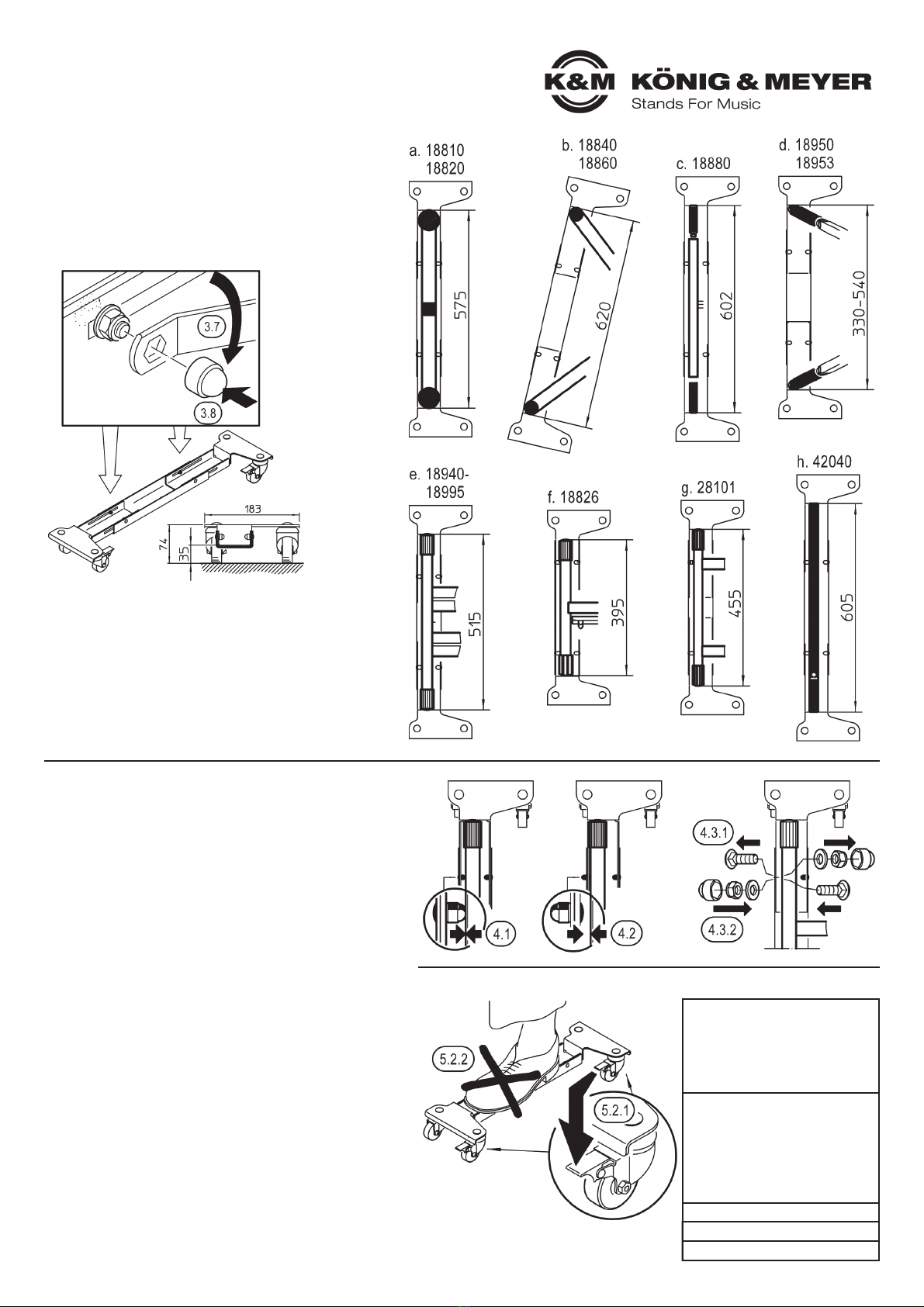
-18810 Keyboardtisch »Omega«
-18820 Keyboardtisch »Omega Pro«
-18826 Geräteständer
-18840 Keyboardständer »Baby-Spider Pro«
-18860 Keyboardständer »Spider Pro«
-18880 Keyboard-Ausbautisch
-18930 Keyboardständer
-18933 Keyboardständer
-18940 Keyboardständer
-18950 Keyboard-Klapptisch
-18953 Stagepiano-Klapptisch
-18962 Keyboardständer
-18963 Keyboardständer
-18969 Keyboardständer für Kinder
-18990 Keyboardständer »Rick«
-18993 Keyboardständer »Rick 20«
-18995 Keyboardständer
-28101 Geräteständer
-42040 Mixerständer
- Sicherer Stand durch exakte Fixierung der Füße
- Nicht nur für den Transport geeignet.
-Dank feststellbarer Rollen kann das Stativ auch
-während des Spiels auf den Rollschlitten verbleiben
- Tragfähigkeit: 80 kg
SICHERHEITSHINWEISE
1. BESTANDTEILE
Bitte Sichtprüfung vornehmen, ob alle Teile vollständig
vorhanden und soweit erkennbar in Ordnung sind.
Beide Rollschlitten sind bereits vormontiert und bestehen aus:
aRollenträger rechts (2 Rollen, 1x feststellbar)
bRollenträger links (2 Rollen, 1x feststellbar)
cU-Halteschiene
dVerschraubungen (4 Sätze pro Schlitten):
dSchloßschraube M5x12, U-Scheibe, Sicherungsmutter M5
Hinzu kommt ein Zubehörbeutel mit:
eSchraubenschlüssel SW8/SW13 zur Fixierung von d
f Schutzkappen (8x, ø11) zur Abdeckung von Mutter und Gewinde
2. ZUSAMMENBAU / UMBAU
Die Rollschlitten sind weitgehend schon
vormontiert und müssen lediglich an die
Keyboardständer angepasst werden.
3. EINSTELLUNG der
3. SCHLITTENLÄNGE
ALLGEMEIN (3.1 - 3.9)
3.1 Schutzkappen abziehen
3.1 (Hinweis: im Falle der Erstinstallation
3.1 befinden sich diese Kappen noch im
3.1 Zubehörbeutel)
3.2 Sicherungsmuttern lockern
3.2 - mit Schlüssel SW8
3.3 Rollenträger auseinanderziehen
3.4 Stativ in Rollschlitten einstellen
3.5 Rollenträger sanft zusammen-
3.5 schieben bis sie an den Füßen
3.5 des Keyboards anstehen
ALLGEMEIN
- Bitte beachten Sie die Angaben dieser Aufstellanleitung.
- Ebenfalls zu beachten sind Sicherheitsanweisungen und Anleitungen der
-eingesetzten Stative.
- Die Schlitten dienen ausschließlich zum Transport der hier angegebenen
-K&M-Stative (a. - h.); sowie der ordnungsgemäß aufgebrachten Lasten. Andere
-Stative, Gestelle, Möbel etc. sind nicht erprobt und entsprechen daher nicht dem
-bestimmungsgemäßen Gebrauch.
- Tragfähigkeit: 80 kg
- Die Möglichkeit, das Produkt zu verstellen, birgt naturgemäß Einklemmgefahren.
-Umsichtige und aufmerksame Handhabung bei Aufbau, Betrieb, Abbau und Wartung
-sind daher unverzichtbar.
- Vor Nässe schützen.
BETRIEB
- Vor Benutzung auf Vollständigkeit und Funktionsfähigkeit prüfen.
- Beschädigte Teile müssen vor Gebrauch entweder ersetzt oder erst wieder
-instandgesetzt werden
- Der sichere Sitz der Stative ist stets zu gewährleisten. Dies geschieht insbesondere
-durch die Anpassung der Rollschlitten an die jeweiligen Abmessungen der diversen
-Stative.
- Auf feste Schraubverbindungen aller beteiligten Artikel ist zu achten
- Während des Transports ist das Ensemble stets mit der Hand am Keyboardständer
-zu führen
- Die Rollschlitten (auch unbelastet) nicht auf schiefer Ebene abstellen.
- Im Standbetrieb sind jeweils beide Fußrollenbremsen festzustellen
- Bei ungünstigen Bodenverhältnissen (weiche Beläge, schiefe Ebenen, Absätze,
-Hindernisse u.ä.) bitte erhöhte Vorsicht walten lassen. Das gilt insbesondere für den
-Transportbetrieb (Erschütterungen, Kippmomente) aber auch für den Standbetrieb.
- Das Abstellen der Füße auf den Rollschlitten ist nicht erlaubt.
- Zur Reinigung am besten ein leicht feuchtes Tuch und ein nicht scheuerndes
-Reinigungsmittel benutzen.
Vielen Dank, dass Sie sich für dieses Produkt entschieden haben.
Bitte lesen und beachten Sie vor Aufbau und Betrieb dieses
Produkts sorgfältig diese Anleitung. Sie informiert Sie über alle
wichtigen Schritte um eine sichere Handhabung zu gewährleisten.
Wir empfehlen, sie auch für den späteren Gebrauch
aufzubewahren.
KÖNIG & MEYER GmbH & Co. KG
Kiesweg 2, 97877 Wertheim, www.k-m.de
18806-000-55 Rev.12 03-80-337-00 6/21

TECHNISCHE DATEN
MATERIAL
Profile, Platten, Winkel, Krallen:
Stahl, pulverbeschichtet schwarz
Schrauben, Scheiben:
Stahl verzinkt,
Kunststoffteile: PA, PE, schwarz
ABMESSUNGEN
Außenmaße:
L x B x H: 564/787 x 183 x 78 mm
Keyboard-Fußabstand:
395 - 620 mm
Höhe: Gesamt 74 mm;
U-Halteschiene 35 mm
TRAGFÄHIGKEIT 80 kg
KARTON 700 x 210 x 110 mm
GEWICHT 7,1 kg
3. EINSTELLUNG der
3. SCHLITTENLÄNGE
ALLGEMEIN (3.1 - 3.9)
3.6 Stativ aus dem Rollschlitten entnehmen
3.7 Sicherungsmutter wieder fest anziehen
3.8 Schutzkappen auf Muttern schieben
3.9 Stativ wieder in die Rollschlitten stellen:
3.9 a. - h. (div. K&M-Stative)
TIPPS
- Wir raten dazu, diesen einmal eingestellten Abstand so zu belassen
- Jedoch, erneute Verstellungen können notwendig sein...
-...beim Wechsel des Stativs (siehe a. - h.)
-...um den Rollschlitten so kompakt wie möglich zusammen-
-zulegen (z.B. aus Transport- oder Lagerungsgründen)
- Beim Verstellen der Rollschlitten vorgehen wie beschrieben
-(siehe 3.1 - 3.9)
- Bitte beachten Sie, dass der Rollschlitten Ihr Keyboard um
-35 mm anhebt, wodurch evtl. eine Anpassung der Stativhöhe
-erforderlich ist
4. ANPASSUNG an X-Ständer
4.1 FALL
4.1 - die Fußrohre der X-Ständer liegen an den Schutzkappen der
4.1 - Verschraubungen an (s. Kap. 1.BESTANDTEILE: f).
4.2 EMPFEHLUNG
4.2 - Verschraubungen umkehren, so dass sich die Schutzkappen
4.2 - außen und die flacheren Schraubenköpfe innen befinden. So
4.2 - liegen die Parkettschoner und nicht die Fußrohre an.
4.3 VORGANG
4.3.1 - Schutzkappen abheben und Verschraubung vollständig lösen
4.3.2 - Schraube nun von innen durchschieben, Scheibe aufbringen,
5.3.2 - Sicherungsmutter festdrehen, Schutzkappe wieder aufpressen
5. IM EINSATZ
Sobald der Keyboardständer in die entsprechend angepassten
Rollschlitten eingestellt wurde, kann es losgehen.
5.1 TRANSPORTBETRIEB
5.1 - Während des Transports ist der Keyboardständer stets mit der
5.1 -Hand zu führen.
5.1 - Bei ungünstigen Bodenverhältnissen (weiche Beläge, schiefe
5.1 -Ebenen, Absätze, Hindernisse u.ä.) ist erhöhte Vorsicht
5.1 -erforderlich. Das gilt insbesondere für den Transportbetrieb
5.1 -(Erschütterungen, Kippmomente), aber auch für den
5.1 -Standbetrieb.
5.2 STANDBERIEB
5.2.1 - Wir empfehlen jeweils beide Fußrollenbremsen festzustellen
5.2.2 - Das Abstellen der Füße auf den Rollschlitten ist nicht erlaubt.
5.2.3 - Die Rollschlitten (auch unbelastet) nicht auf schiefer Ebene
6.2.3 - abstellen, selbst bei festgestellten Fußrollen nicht.

SETUP INSTRUCTIONS
18806 Trolley for
keyboard stand
- suitable for the following products:
-18810 Table-style keyboard stand »Omega«
-18820 Table-style keyboard stand »Omega Pro«
-18826 Equipment stand
-18840 Keyboard stand »Baby-Spider Pro«
-18860 Keyboard stand »Spider Pro«
-18880 Table-style keyboard stand
-18930 Keyboard stand
-18933 Keyboard stand
-18940 Keyboard stand
-18950 Table-style keyboard stand
-18953 Table-style stage piano stand
-18962 Keyboard stand
-18963 Keyboard stand
-18969 Keyboard stand for kids
-18990 Keyboard stand »Rick«
-18993 Keyboard stand »Rick 20«
-18995 Keyboard stand
-28101 Monitor stand
-42040 Mixer stand
- Secure stand with exact fitting of the feet
- Not only suited for transport.
-Thanks to the locking casters the stand can
-remain on the trolleys during use
- Load-bearing capacity: 80 kg
SAFETY NOTES
1. COMPONENTS
Please visually inspect whether all parts are
complete and in order, as far as recognisable.
Both trolleys are pre-assembled and consist of:
aCaster brackets right (2 casters, 1 x lockable)
bCaster brackets left (2 casters, 1 x lockable)
cU-Support rail
dScrewings (4 sets per trolley):
dLocking screw M5x12, washer, lock nut M5
An accessory bag is also included:
eWrench SW8/SW13 for fixing d
fProtective caps (8x, ø11) to cover nut and thread
2. ASSEMBLY / CONVERSION
The trolleys come largely preassembled
and only need to be fitted to the
keyboard stand.
3. ADJUSTMENT of the
3. TROLLEY LENGTH
GENERAL (3.1 - 3.9)
3.1 Remove protective caps
3.1 (Note: in case of initial installation
3.1 caps are still in accessory bag)
3.2 Loosen safety nuts
3.2 - with SW8 key
3.3 Pull the caster brackets apart
3.4 Place stand in trolley
3.5 Carefully push the caster brackets
3.5 together until they have contact with
3.5 the keyboard legs
GENERAL
- Please consider the information provided in the setup instructions
- Please also follow the individual stand safety instructions
- The trolleys are only to be used exclusively for the transport of the listed
-K&M stands (a.- h);
-properly placed on the trolleys. Other stands, racks, furniture etc.
-have not been tested for use on the trolleys and as such do not comply
-with the intended use on the trolleys
- Load-bearing capacity: 80 kg
- The option that the product is adjustable, can result in the risk of
-pinching/wedgingof your fingers. Careful and attentive handling during setup,
-operation, and disassembly is indispensable.
- Protect against moisture.
OPERATION
- Prior to use check to ensure that the system is fully functional and complete
- Damaged parts must be repaired or replaced prior to use
- Ensure that the stand is stable prior to use - This is insured through adjusting the
-trolleys to the respective dimensions of the various stands.
- Ensure that the screws are tight on all of the involved products
- During transport the ensemble may only be moved by ensuring that the
-keyboard stand is being held manually
- Do not place the trolley (even if unloaded) on an inclined plane
- When using the trolleys stationary, both caster brakes must be locked
- In the case of poor surfaces (soft surfaces, inclined planes, stairs, obstacles
-among others) please be particularly careful. This applies in particular to transport
-(vibrations, tipping) but also if the trolleys are used stationary.
- Placement of the feet on to the trolley this not permitted.
- To care for the product, use a damp cloth and a non-abrasive cleaning agent.
Thank you for choosing this product. Please read and follow
carefully these instructions before setting up and operating this
product. It informs you about all important steps to ensure safe
handling. We recommend you keep these instructions for future
reference.
KÖNIG & MEYER GmbH & Co. KG
Kiesweg 2, 97877 Wertheim, www.k-m.de
18806-000-55 Rev.12 03-80-337-00 6/21
TECHNICAL DATA
MATERIAL
Profiles, plates, brackets, claws:
Steel, powder coating, black
Screws, disks:
Steel, galvanized
Plastic parts: PA, PE, black
DIMENSIONS
External dimensions
L x W x H 564/787 x 183 x 78 mm
Keyboard feet/leg distance:
395 - 620 mm
Height: Total 74 mm;
U-Support 35 mm
LOAD-BEARING CAPACITY 80 kg
BOX 700 x 210 x 110 mm
WEIHGHT 7.1 kg
3. ADJUSTMENT of the
3. TROLLEY LENGTH
GENERAL (3.1 - 3.9)
3.6 Remove stand from the trolleys
3.7 Re-tighten safety nut
3.8 Place protective caps onto the nuts
3.9 Place stand back on the trolleys:
3.9 a. - h. (various K&M-Stands)
TIPS
- We recommend refraining from changing the set distance
- However, it may become the necessary to make new
-adjustments...
-...when changing the stand (see a. - h.)
-...to collapse the trolleys to the smallest footprint possible
-(for example, for transport or storage purposes)
- When adjusting the trolleys follow the steps as described
-(see 3.1 - 3.9)
- Please note that the trolley lifts your keyboard up to 35 mm,
-which may require an adjustment of the stand height
4. ADAPTATION - to X-Stands
4.1 CASE
4.1 - The leg tubes of the X stands are placed on the protective
4.1 - caps of the screw connections (see section 1 components: f).
4.2 RECOMMENDATION
4.2 - Reverse the screw connections so that the protective caps are
4.2 - on the outside and the flat screw heads are on the inside. This
4.2 - way, the end caps have contact and not the leg tubes.
4.3 PROCESS
4.3.1 - Remove protective caps and loosen screwing completely
4.3.2 - Now insert the screw from the inside, placed the disc,
4.3.2 - tighten the safety nut, press on the protective cap.
5. IN USE
As soon as the keyboard stand is placed on the adjusted trolleys,
you can start moving it.
5.1 TRANSPORT MODE
5.1 - During transport, the keyboard stand must always be carried
5.1 -by hand.
5.1 - In case of unfavorable ground conditions (soft surfaces,
5.1 -obstacles, steps, inclined planes) increased caution is
5.1 -required. This applies particularly in the case of transport
5.1 -(vibrations, tipping,) but also in the case of stationary use.
5.2 STATIONARY MODE
5.2.1 - We recommend that both caster brakes are locked
5.2.2 - The placement of the feet on to the trolleys this not permitted.
5.2.3 - Do not place the trolleys (even unloaded) on an inclined
6.2.3 - plane, even if the casters brakes are locked.
This manual suits for next models
1
Table of contents
Languages:
Other Konig & Meyer Outdoor Cart manuals


