Konig & Meyer Overture User manual

SICHERHEITSHINWEISE
a. Der Wagen dient ausschließlich zum Transport von bis zu 12 Orchesternotenpulten Art.-Nr. 11930,
a. 11924, 11925. Andere Lasten sind nicht zulässig; insbesondere Personentransporte sind untersagt.
b. Der beste Schutz des Wagens, der Notenpulte und der Umgebung ist das vorsichtige Fahren
b. mit dem 11935.
c. Der Wagen muss immer geführt werden. Freies Fahren ist nicht erlaubt und eine Risikoquelle.
d. Der Untergrund muss für den Einsatz von Rollen geeignet sein. Dazu zählt ein ebener, tragfähiger Boden.
e. Bei Hindernissen auf dem Boden (Leisten, Absätze, Kabel etc.) besondere Vorsicht walten lassen.
f. Wagen und insbesondere die Lenkrollen regelmäßig auf Sauberkeit und Funktion prüfen.
g. Lenkrollen stets mit den Füßen bedienen - bei Handbetätigung besteht Quetschgefahr.
h Nach dem Abstellen des Wagens sollten die beiden beweglichen Lenkrollen festgestellt werden.
i. Wagen nicht auf schiefer Ebene abstellen bzw. parken.
j. Platzieren und sichern Sie die Notenpulte auf dem Wagen stets in der vorgesehenen Art und Weise.
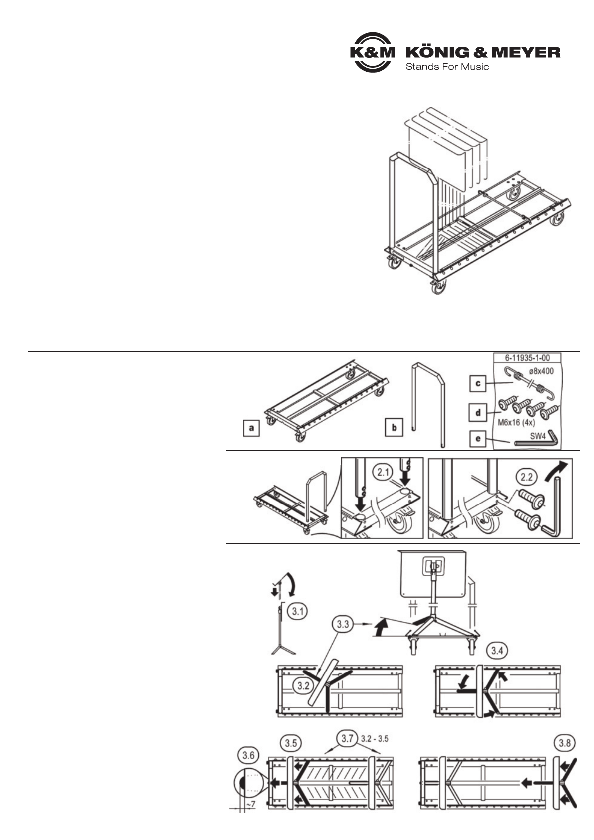
1. BESTANDTEILE
- Teile vorsichtig der Verpackung entnehmen und auf
-dem Boden auslegen.
- Sichtprüfung vornehmen, ob alle Teile vorhanden und
-- soweit erkennbar - in Ordnung sind.
aTransportwagen mit 2 Feststellrollen und 2 Bockrollen
bGriffrohr
Zubehörbeutel:
cGummiseil mit 2 Haken, ø8 x 400 mm
d4x Inbusschraube M6 x 16 mm
eInbusschlüssel SW4
2. MONTAGE
2.1 Griffrohr bin die Bohrungen am Rahmen des
2.1 Transportwagens aeintauchen lassen
2.2 Inbusschrauben dseitlich am Rahmen ansetzen und
2.2 damit beide Enden des Griffrohres fest mit dem
2.2 Transportwagen verschrauben (4x).
2.2 Dazu den Inbusschlüssel ebenutzen.
3. BELADEN des WAGENS
mit den dafür vorgesehenen Orchesternotenpulten
(=ONP) 11930, 11924 und 11925.
3.1 Klappen Sie die Platten des Notenpultes senkrecht
3.1 nach unten und fahren Sie das Auszugrohr so weit
3.1 wie möglich ein. Gründe:
3.1 - Dies ermöglicht minimale Abstände zwischen
3.1 -den ONP (70 mm) und führt zur maximalen Aus-
3.1 -nutzung der Transportkapazitäten von bis zu 12 ONP.
3.1 - Ein tiefer Schwerpunkt der Ladung verbessert die
3.1 -Fahreigenschaften.
3.2 Dreifuß des ONP auf dem Wagen abstellen
3.3 Heben Sie den Einzelfuß der in Richtung des Griff-
3.3 rohres bzeigt, etwas an...
3.4 ...und verdrehen den Dreifuß so weit, bis der er-
3.4 hobene Fuß in der mittleren Schiene platziert werden
3.4 kann. Die beiden anderen Füße tauchen dabei auto-
3.4 matisch unter die seitlichen Führungsschienen.
3.5 Schieben Sie nun das Stativ in Richtung Griffrohr bis
3.5 zum Anschlag.
3.6 Zur Kontrolle: ein kleines Stück des Fußes ragt aus
3.6 dem Rahmen hervor.
3.7 Verfahren Sie mit den weiteren ONP genauso wie in
3.7 den Punkten 3.2-3.5 beschrieben.
3.8 ALTERNATIV können Sie die Dreifüße auch ganz
3.8 vorne in die Schiene setzen und dann Richtung
3.8 Griffrohr schieben.
Vielen Dank, dass Sie sich für dieses Produkt entschieden haben. Diese Anleitung informiert Sie
über alle wichtigen Schritte bei Aufbau und Handhabung.Wir empfehlen, sie auch für den
späteren Gebrauch aufzubewahren.
AUFSTELLANLEITUNG 1. BESTANDTEILE
2. MONTAGE
3. BELADEN des WAGENS
11934 Wagen für Orchester-
notenpulte »Overture«
BESTIMMUNGSGEMÄSSER GEBRAUCH
- Maßgeschneiderter Transportwagen für bis zu 12 Orchesternotenpulte 11930
-sowie auch für die K&M-Modelle 11924 und 11925
- Sicher, robust, schlank und schnell
- Einfach in der Montage und Handhabung
- Mit hochwertigen, große Rollen
- Zusätzliche Sicherung durch Gummiseil
- Platzbedarf, B x T x H: 490 x 1180 x 165 (925) mm, 13,4 kg

BENUTZERHINWEISE / FUNKTIONEN
5. ABMESSUNGEN
6. ROLLEN
6.1 Lenkrollen mit Feststeller (2x)
6.1 - befinden sich unterhalb des Griffrohres
6.2 Bockrollen, feststehend (2x)
7. KAPAZITÄT
7.1 Bis zu 12 Orchesternotenpulte der Baureihe
7.1 K&M 11930, 11924 und 11925
8. BETRIEBSARTEN
8. - siehe auch Kapitel SICHERHEITSHINWEISE
8.1 TRANSPORTBETRIEB
8.1 - Griffrohr bmit der Hand festhalten.
8.1 - Feststeller beider Lenkrollen 6.1 mit dem Fuß lösen
8.1 - Mit der Hand am Griffrohr den Wagen in die
8.1 -gewünschte Richtung führen.
8.1 HINWEIS: Während des Transportbetriebes das
8.1 HINWEIS: Griffrohr des Wagens nicht loslassen.
8.2 STANDBETRIEB
8.2 - Feststeller beider Lenkrollen müssen eingerastet, d.h.
8.2 -nach unten gedrückt sein. Bremsen per Fuß betätigen.
8.2 HINWEIS: Wagen niemals auf schiefer Ebene abstellen.
PRÜFEN, INSTANDHALTEN
- Bei Wartungsarbeiten auf evtl. Gefährdungen achten
-(Einklemmen...)
- Zur Reinigung am besten ein leicht feuchtes Tuch und
-ein nicht scheuerndes Reinigungsmittel benutzen
FEHLERSUCHE (F) und BESEITIGUNG (B)
F: Griffrohr bwackelt
F: B: Schraubverbindungen 2.2 überprüfen und
F: B: ggf. nachziehen oder ersetzen
F: Wagen kippelt oder rollt nicht richtig
F: B: Fußrollen überprüfen, ggf. ersetzen 6
F: B: Untergrund auf Eignung prüfen
F: Orchesternotenpulte (ONP) wackeln
F: B: ONP wie beschrieben (siehe 3.2-3.8) platzieren
F: B: Spanngurt anbringen 4.1, 4.2
F: B: ONP so weit wie möglich einfahren 3.1
5. ABMESSUNGEN 6. ROLLEN
7. KAPAZITÄT
8. BETRIEBSARTEN
KÖNIG & MEYER GmbH & Co. KG
Kiesweg 2, 97877 Wertheim, www.k-m.de
11934-000-55 Rev.02 03-79-942-00 1/22
TECHNISCHE DATEN
Material
Rohre, Schienen: Stahl pulverbeschichtet
Verbindungselemente: Stahl, verzinkt
Kantenschutzprofil: Stahl, PVC
Rollen: TPE
Tragfähigkeit bis zu 12 Orchesternotenpulte
Abmessungen B x T x H: 490 x 1180 x 165 (925) mm
Rollen: ø100 mm, Bodenfreiheit: 112 mm
Gewicht 13,4 kg
Karton 1230 x 570 x 210 mm
4. SICHERN der LADUNG
Um ungewollte Bewegungen der Ladung zu
verhindern, wird über den letzten Dreifuß
stets ein Gummiseil cgespannt.
4.1 Führen Sie einen Haken des
4.1 Gummiseils in das passende
4.1 Loch eine der beiden seitlich-
4.1 en Führungsschienen
4.2 Spannen Sie das Seil über die beiden Füße
4.2 und haken Sie es in das entsprechende
4.2 Loch der anderen Schiene ein
4. SICHERN der LADUNG
SAFETY INSTRUCTIONS
a. The trolley is only to be used for the transportation of up to 12 orchestra music stands Art.-Nr. 11930,
a. 11924, 11925. Other loads are not permissible; in particular the transport of individuals is prohibited.
b. The best way to protect the trolley, the music stands and the surroundings is to maneuver
b. the 11935 Trolley carefully.
c. The trolley must always be guided. Pushing the trolley is not permitted and is a source of risk.
d. The surface must be suitable for casters. The surface must be even and weight-bearing.
e. In the case of obstacles (moldings, carpets, rugs, landings among others) be sure to maneuver
e. the trolley very carefully.
f. Inspect the trolley, in particular the casters to ensure that they are clean and in functioning order.
d. Casters are always to be operated using one's foot - using one's hand bears the risk of pinching or wedging one's hand.
h. When the trolley is not in use the two movable casters brakes should be set.
i. Do not park the trolley on a sloping surface.
j. Place and secure the music stands on the trolley according to the instructions.
1. COMPONENTS
- Carefully remove the parts from the package and
-place them on the floor.
- Visually inspection whether all parts are present and
-- as far as can be seen - in good order.
aTransport trolley with 2 locking casters and 2 fixed casters.
bHandle tube
Accessory bag:
cRubber cord with 2 hooks, ø8 x 400 mm
d4x hexagon socket screws M6 x 16 mm
eAllen wrench/hexagon key SW4
2. ASSEMBLY
2.1 Place the handle tube into bthe drill hole located on
2.1 the frame of the transport trolley a
2.2 Place the hexagon socket screws dinto the side of
2.2 the frame and screw both ends of the handle tube to
2.2 the transport trolley (4x). To accomplish this use the
2.2 Allen wrench / hexagon key e.
3. LOADING the TROLLEY
Load the trolley with the orchestra music stands 11930,
11924 and 11925 designed for the trolley.
3.1 Flip the music desk of the music stand down and
3.1 retract the extension tube as far as it will go. Reasons:
3.1 - This ensures the minimum distance between the
3,1 -orchestra music stands (70 mm) and results in the
3.1 -maximum use of the transport capacity of up to 12
3.1 -orchestra music stands.
3.1 - A lower center of gravity of the load improves the
3.1 -maneuverability of the trolley.
3.2 Place the tripod of the orchestra music stand on the
3.2 trolley
3.3 Lift the individual leg in the direction of the handle
3.3 tube ba bit...
3.4 ...and turn the tripod until the lifted leg can be placed
3.4 in the middle rail. The other two legs automatically
3.4 are placed under the side guide rails.
3.5 Now move the stand in the direction of the handle
3.5 tube as far as it will go.
3.6 Check: a small portion of the leg sticks out from the
3.6 frame.
3.7 Continue with the other orchestra music stands in
3.7 the same manner as described in Points 3.2-3.5.
3.8 ALTERNATIVELY the tripod can also be placed at
3.8 the front in the guide rails and then we pushed in the
3.8 direction of the handle tube.
Thank you for choosing this product. The instructions provide directions to the important setup
and handling steps. We recommend you keep these instructions for future reference.
SETUP INSTRUCTIONS 1. COMPONENTS
2. ASSEMBLY
3. LOADING the TROLLEY
11934 Trolley for orchestra
music stands »Overture«
INTENDED USE
- Customized trolley for up to 12 orchestra music stands 11930
-and also for K&M models 11924 and 11925
- Sturdy, robust, slim and quick
- Simple installation and handling
- With high quality, large casters
- Additional securing by rubber cord
- Space requirement, W x D x H: 490 x 1180 x 165 (925) mm, 13.4 kg

USAGE NOTES / FUNCTION
5. DIMENSIONS
6. CASTERS
6.1 Swivel casters with brakes (2x)
6.1 - are located below the handle tube
6.2 Fixed castors, stationary (2x)
7. CAPACITY
7.1 Up to 12 orchestra music stands of the
7.1 K&M series 11930, 11924 and 11925
8. OPERATION MODES
8. - see also chapter SAFETY INSTRUCTIONS
8.1 TRANSPORT MODE
8.1 - Hold the handle tube bwith your hand.
8.1 - Release the brakes of both swivel castors 6.1 with
your foot.
8.1 - Guide the trolley in the desired direction with
8.1 -the hand on the handle tube.
8.1 NOTE: Do not release the handle tube of the trolley
8.1 NOTE: during transport mode.
8.2 PARKING MODE
8.2 - Brakes on both swivel casters must be engaged, i.e.
8.2 -pressed down. Apply brakes by foot.
8.2 NOTE: Never park the trolley on an inclined plane.
CHECK, MAINTENANCE, CLEANING
- In the event of workstation maintenance pay attention
-to possible risks (wedging…)
- To care for the product use a damp cloth and a non-
-abrasive cleaning agent
FAULT-FINDING (F) and REPAIR (R)
F: Handle tube bis not stable
F: R: Check screw connections 2.2 and
F: R: tighten or replace as needed
F: The trolley tips or does not roll properly
F: R: Check the casters, replace if needed 6
F: R: Check if the surface is suitable
F: Orchestra Music Stands moves back and forth
F: R: Place orchestra music stands (see 3.2-3.8) as
F: R: described above
F: R: Place rubber cord 4.1, 4.2
F: R: Place the orchestra music stand as far as they
F: R: will go towards the handle tube 3.1
5. DIMENSIONS 6. CASTERS
7. CAPACITY
8. OPERATION MODES
KÖNIG & MEYER GmbH & Co. KG
Kiesweg 2, 97877 Wertheim, www.k-m.de
11934-000-55 Rev.02 03-79-942-00 1/22
TECHNICAL DATA
Material
Tubes, guide rails: Steel, powder coating
Connection elements: Steel, galvanized
Edge protection profile: Steel, PVC
Casters: TPE
Load capacity up to 12 Orchestra music stands
Dimensions W x D x H: 510 x 1180 x 165 (925) mm
Casters: ø100 mm, Ground clearance: 112 mm
Weight 13.4 kg
Packaging 1230 x 570 x 210 mm
4. SECURING the LOAD
To avoid unintentional movement of the
load a rubber cord cis used to secure the
load.
4.1 Guide the rubber cord hook
4.1 into the drill holes on both
4.1 sides of the side guide rails
4.2 Secure the cord over both legs and hook it
4.2 into the hole located on the other guide rail
4. SECURING the LOAD
This manual suits for next models
2
Table of contents
Languages:
Other Konig & Meyer Outdoor Cart manuals


