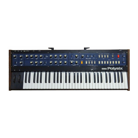
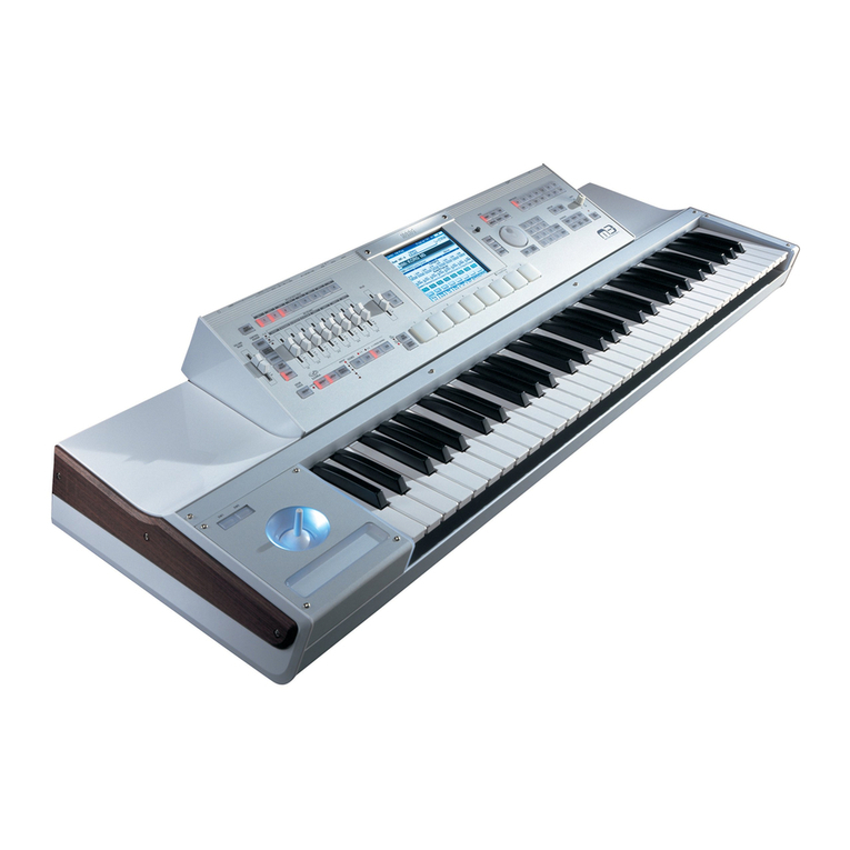
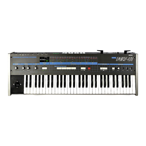
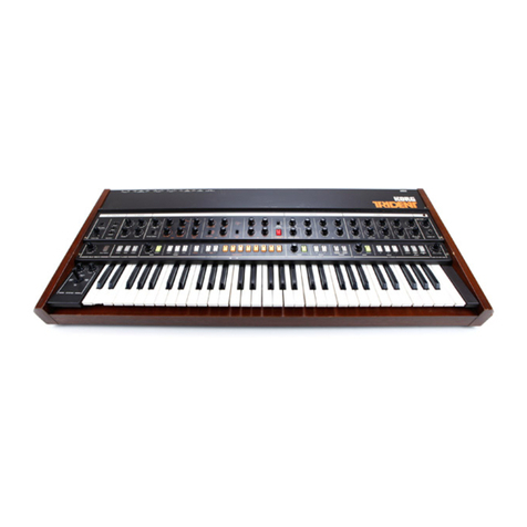
Korg Trident Mk II User manual

KORG lRIDEN^kH
Performing Keyboard
Owner's Manual
Bedienungsanleitung
Mode demploi
•WM
1
7
8
9
)
16' 8-
OFF «* 4-
•
OCTAVE
J
•
!• 8
DETUNE
VC0 2
LOAOMG FOUMO
S3u •-•
VCFEG
CUTOFF FREO RESONANCE
HAIF
QUARTER FULL
KBD TRACK EG INTENSITY
TO TAK FTtOH TAP* VtfOFV EMIOfl/CAMCEL
VCAEG
SYNTHESIZER
KORG

KORG 1RIDENUH
Performing Keyboard
Thank you for choosing the Korg
Trident Mk.II. This remarkable instrument
provides the variety and flexibility of a
stack of several keyboards, all packed
into one. It's asuper polyphonic
ensemble featuring memory equipped
8-voice polyphonic synthesizer plus
brass plus strings. And you can assign
each section to the upper 3octaves or
lower 2octaves of the full 61-key key-
board, as you like. For added conven-
ience, the Trident Mk is is equipped with
abuilt-in flanger, joy stick, presets and
multiple interface jacks. This instruction
manual is designed to give you full
details about getting the most out of this
remarkable instrument.
WARNING
To reduce the risk of fire or electric shock do
not expose this appliance to rain or moisture.
Wir mochten uns bei dieser Gelegen-
heit dafur bedanken, daB Sie sich fur den
Korg Trident Mk.ll entschieden haben.
Dieses bemerkenswerte Instrument
bietet Ihnen die Vielfaltigkeit und Flexi-
bilitat von mehreren Keyboards in einem.
Es ist ein erstklassiges polyphonisches
Ensemble mit einem programmierbaren
8-voice polyphonen Sythesizer sowie
einem kompletten Bias- und Streichin-
strumente-Simulatorteil. AuBerdem
lassen sich die Manualteile der drei
oberen Oktaven Oder die der zwei
unteren Oktaven bei einer vollen 61-
Tasten-Klaviatur getrennt regulieren. Ein
eingebauter Flanger, der Joy-stick-
Steuerhebel, Voreinstellungen und
multiple-lnterface-Buchsen ermog-
lichen Ihnen eine leichte Bedienung.
Diese Bedienungsanleitung soil Sie mit
alien Funktionen dieses hochwertigen
Instrumentes vertraut machen.
Nous vous remen<;ions d'avoir porte
votre choix sur le Trident Mk.II KORG.
Ce remarquable instrument de musique
offre ala fois la variete et la flexibility de
plusieurs claviers reunis en un seul. C'est
un super ensemble polyphonique dote
de memoire et equipe d'un synthetiseur
polyphonique acuivres et acordes. Vous
etes loisible d'affecter chaque section
aux 3octaves superieures ou aux 2
octaves inferieures d'un clavier complet
a 61 touches, en toute liberie. En
complement a sa commodite, le Trident
est muni d'un variateur de phase, levier
de reglage variable (joy-stick), de jacks
de presets et d'interface multiple. Ce
manuel d'instructions est etudie pour
prodiguer tous les details necessaires
qui peuvent permettre d'exploiter au
maximum ce remarquable instrument.
Handling precautions
•Always be sure to use the correct AC line
voltage. II line voltage is 90% or less of rated
voltage. S/N ratio and stajility will suffer. If
you have any reason to believe the AC volt-
age is too low, have it checked with avolt-
meter before you turn on the power supply
switch.
•Do not use any lype of plug except lor
slandard phone plugs, (guitar type) in the
KORG TRIDENT input and output lacks.
•Avoid using or storing your KORG TRI-
DENT Mk.II in very hot, cold, or dusty
places.
VorsichtsmaBnahmen bei
der Handhabung
•Immer auf die richtige. Netzspannung
achten. Falls die Netzspannung weniger als
90% der Nennspannung betragt, dann
kommi es zu einer Verschlechterung des
Fremdspannungsabslandes und der Sta-
bility. Im Zweilelsfall sollte die Netzspan-
nung mit einem Voltmeter kontrollierl wer-
den, bevor der Netzschalter eingeschaltet
wird.
•Niemals andere als normale Phono-
Stecker an die Ein- und Ausgangsbuchsen
von Modell KORG TRIDENT Mk.II
anschlielSen.
•Dieses Gerat nicht an heiGen, kalten oder
staubigen orten verwenden bzw. aufbe-
wahren.
Precautions
•La boite arythme doit toujours etre ali-
menlee par la tension secteur appropriee.
Si la tension du secteur ne represente que
90% ou moins de la tension nominale, le
rapport signal sur bruit et la stabilite en
souffriront. Si vous pensez que la tension
secteur alternative est insuffisante, pro-
cedez aune verification avec un voltmetre
avanl de remettre I'interrupteur general en
position de marche.
•Ne pas utiliser d'autres fiches que des
liches standard pour realiser les raccorde-
ments aux prises d'entree et de sortie du
KORG TRIDENT Mk.II.
•Eviter de mettre en service ou de con-
server cet appareil dans un local atem-
perature elevee, basse ou dans un endroit
poussiereux.
Trident Mk II

Features
Wichtige Merkmale
Prestations
Includes the full capabilities
of three complete key-
boards in one: 8-voice program-
mable polyphonic synthesizer,
brass and strings.
Drei vollwertige Keyboard in
einem: Ein programmier-
barer 8-voice polyphoner Syn-
thesizer, Bias- und Streich-
ensemble.
Presente I'avantage de reunir
les possibility de trois
claviers complets erjun seul:
synthetiseur polyphonique pro-
grammable a8voix, cuivres et
cordes.
OO Programs stored in memory
O^- allow the user to create
his own sounds for instantaneous
recall at the push of abutton.
Full edit capabilities allows the
user to make temporary or
permanent changes to any program,
and to move programs about
in memory
O/Vverschiedene mit dem poly-
%J^Lphonen Synthesizer erzeugte
Farbtone kbnnen intern gespei-
chert und sofort abgerufen
werden. Die Montagefunktion
erlaubt Ihnen, abgerufene Klang-
farben zu andern und die korri-
gierte Klangfarbe dann wieder
im Speicher abzulegen. Mit Hilfe
des Cassetten-lnterface konnen
unendlich viele Farbtone auf
Cassettenband gespeichert werden.
OOtimbres differents crees par
Ofcun synthetiseur polyphoni-
que et pouvant etre mis en me-
moire aux fins de rappel instan-
tane. La fonction de montage
vous permet de modifier les tim-
bres rappeles et de mettre en
memoire le timbre corrige.
L'interface magnetophone vous
permet de mettre en memoire
sur cassette une variete infinie de
donnees relatives aux timbres.
Rapid, 8-second Cassette Tape
Interface capabilities provides
unlimited additional program
storage, allowing you to create
program libraries for later use.
Keyboard split controls let
you assign each section
(synthesizer, brass, strings) to
either the upper or lower ends of
the keyboard, or both. So you
have as much or more flexibility
and variety as playing two
separate keyboards!
Durch die Manualteilung der
Tastatur lassen sich ein-
zelne Teile (Synthesizer, Blas-
oder Streichensemble) auf das
obere, untere oder auf beide
Teile des Keyboards verteilen.
Dadurch erhalten Sie die glei-
chen, wenn nicht noch groBere
Mbglichkeiten als durch zwei ver-
schiedene Keyboards!
Les commandes separees du
clavier vous permettent
d'affecter chaque section (synthe-
tiseur, cuivres, cordes) ala
gamme superieure ou ala gamme
gamme inferieure du clavier ou
aux deux. Vous avez done adis-
position autant de souplesse
sinon plus, et de variete, qu'en
jouant sur deux claviers separes.
Thebrass section is equipped
with additional VCF and EG
modules independent from the
polyphonic synthesizer controls.
The strings section features a
unique and original bowing effect
that lends surprising realism.
Unabhangig von der poly-
phonen Synthesizerkon-
trolle wurde der Blaserteil mit
zusatzlichen VCF (spannungsge-
regelte Filter) und EG (Hullkur-
vengeneratoren) versehen.
Erstmalig gelang es im Streicher-
teil einen realistischen "Bogen-
Effekt" zu reproduzieren.
La section des cuivres est
equipee de modules v.c.f. et
generateur d'enveloppe indepen-
dents des commandes du syn-
thetiseur polyphonique. La sec-
tion des cordes caracterise un
effet unique et original de
courbure qui atendance amener
aun surprenant realisme.

oOo o
WMTC
EHAftF TAPC
ENftBLf rooM to e««tssos 5T«WGS BRASS S'NTt*" BRASS STNTM6
VCUcMIN RELEASE SEPARATE OV
STRINGS BRASS WlOUT
S»NT»C ^Oh iOW
fNABU
f>SABU =o occ- <** cr o«sa /«-
<—J 1>ooo
c-5v o-av •sv *sv sv -iV tGND 5V -SV •GND
Synthesizer, rhythm box. sequencer,
(from trigger signal output).
Synthesizer. Rhythmusgerat, Sequencer,
(von der Trigger -Ausgangsbuchse).
Synthetiseur. boite arythme. sequenceur
(Provenant de la sortie de signal du
declencheur).
Foot control pedal (MS-01 ,04)
FuGregler (MS-01, 04)
Pedale de commande au pied. (MS-01 ,04)
I
Cassette tape recorder
Cassettenrecorder
Magnetophone acassette
Korg loot switch (S-1)
Korg Fufischaltung(S-l)
interrupteur au pied Korg
(S-1).
Volume pedal (FK-3)
Tape Echo (SE-300. 500).
Delay (SD-200. 400)
and other etlects.
Lautstarkepedal (FK-3)
Echohallgerat (SE-300. 500).
Verzdgerungseinheit (SD-200. 400)
und andere Eftektgerate.
Pedale de volume (FK-3)
Echo de bande (SE-300. 500),
Retard (SD-200. 400)
et autres etfets.
IiI*i
<0^
53 iimJ
DOC..'.'' •/
MS-20
KR-55.33

Connections AnschluBdiagramm Connexions
Rear Panel Facilities
OWRITE ENABLE
This is the on/off switch for the write
function of the polyphonic synthesizer's
memory. Set to DISABLE when you
want to protect the memory and prevent
storage of new programs. Set to ENABLE
when you want to load programs stored
on cassettes.
@TAPE ENABLE
Set this switch to ENABLE when you
want to use the tape interface to store
programs on tape or retrieve (load)
programs from tape for storage in the
on-board memory. Leave this switch at
DISABLE when not using the tape
interface.
Asmall LED above the switch indicated
selection of Tape interface made; normal
synthesizer and programming functions
are suspended during tape operations.
The LED Switches function as Tape
interface switches and indicators in this
mode.
Note: Be sure both WRITE ENABLE
and TAPE ENABLE are set to DISABLE
when turning the power switch on and
off.
OTAPE FROM/TO
These are the tape interface input and
output jacks. Connect FROM to the tape
recorder's line out jack; connect TO to
the recorder's rec in jack. Set the FROM
switch to HIGH if connected to an
earphone or line output; set to LOW for a
headphone output. Set the TO switch to
HIGH for line in or aux in connections;
set to LOW if connected to a microphone
input (mic in).
OTOTAL EXPRESSION.
Connect afoot pedal (MS-1, 04) to this
jack to control volume of the entire key-
board.
©EXPRESSION.
These three input jacks are tor connec-
tion of separate foot pedals for independent
volume control of each section. Total ex-
pression retains exclusive control of only
those sections not controlled by independ-
ent expression jack inputs.
Note: In other words, if you have one foot
pedal connected to the total expression
jack and another pedal connected to the
Brass expression jack, total expression
pedal will only control the volume of the
strings and synthesizer sections.
Bedienungselemente der Riickplatte Organes sur panneau arriere
OBRASS.
The VCF fcM IN jack lets you use afoot
pedal (MS-01, 04) to control cut-off fre-
quency modulation of the brass section's
VCF. Useful for quick variation of brass
tone color.
The TRIG IN jack lets you use an external
trigger signal (from S-1 foot switch, KR-55
or KR-33 rhythm box, sequencer or syn-
thesizer) to trigger the brass section while
keys are being held down. The trigger
select switch must be on for this effect.
OSYNTHE.
The VCF fcM IN lets you use afoot
pedal (MS-01, 04) to modulate the cut-
off frequency of the synthesizer section
(Control voltage range is —5 to +5V.)
The DAMPER jack is for connecting the
accessory S-1 footswitch for use like a
piano damper pedal to "sustain" thesyn-
the section. When the footswitch is con-
nected, the programmed EG release
times are ignored with the Damper switch
UP, and release time is set to (no
"sustain"). With the Damper switch
DOWN, the programmed EG release
times are used, and the sound is "sus-
tained" according to the programmed
release times. When the footswitch is not
connected, the sound is "sustained"
at all times according to the programmed
release times.
SEPARATE OUT.
These separate SYNTHE, BRASS and
STRINGS outputs let you run each section
through aseparate mixer input or connect
each to aseparate amplifier. Separate
connections add impact and help keep
tone colors distinct.
MIX OUT.
Provides all three sections together in a
single mixed output signal.
HIGH: ahigh (line) level signal for connec-
tion to PA mixer or audio system (AUX)
inputs.
LOW: A low level signal for connection to
guitar amp or vocal amp inputs.
OWRITE ENABLE
Mit diesem Schalter wird die Schreibe-
funktion des Speichers des polyphonen
Synthesizers ein- und ausgeschaltet.
wahlen Sie DISABLE, wenn Sie den
Speicherinhalt schiitzen und die Eingabe
neuer Daten verhindern wollen. Wahlen
Sie ENABLE, wenn Sie am Schaltpult
erzeugte Klangfarben speichern oder auf
Cassetten gespeicherte Daten auffinden
wollen.
TAPE ENABLE
Stellen Sie diesen Schalter auf ENA-
BLE, wenn Sie das Cassetten- Interface
zum Speichern von Daten auf Band bzw.
Wiedergewinnen (Laden) von Daten vor
Band zum Ablegen im internen Speicher
verwenden wollen. Lassen Sie diesen
Schalter auf DISABLE gestellt, wenn Sie
vom Cassetten- Interface nicht Gebrauch
machen.
Zur Beachtung: Achten Sie darauf, daB
beim Ein- und Ausschalten des Netzschal-
ters die beiden Schalter WRITE ENABLE
und TAPE ENABLE auf DISABLE ge-
stellt sind.
©TAPE FROM/TO
Diese Buchsen bilden den Cassetten-
Interface-Eingang und Ausgang. Verbin-
den Sie FROM mit der Direktausgangs-
buchse des Cassettenrecorders und TO
mit seiner Aufnahmebuchse. Bei An-
schlufs an einen Ohrhorerausgang stellen
Sie den FROM-Schalter auf HIGH, bei
Anschlufs an einen Kopfhorerausgang auf
LOW. Bei Direkteingangs- und Reserve-
eingangsanschliissen stellen Sie den TO-
Schalter auf HIGH, bei Anschluft an einen
Mikrofoneingang auf LOW.
OTOTAL EXPRESSION
AnschluB fur einen FuBregler (MS-01,
04), mit dem sich die Lautstarke des ge-
samten Keyboards regulieren IMBt.
©EXPRESSION
Durch diese drei Eingangsbuchsen
konnen mittels separater FuBregler die
Laustarken der einzelnen Teile getrennt
gesteuert werden. Der Haupt-Fuf3regler
(total Expression) regelt dann nur die Teile,
die nicht gerade durch einen anderen
FuBregler (Expression) kontrolliert werden.
Hinweis: Das heist, beim AnschluB eines
FuBreglers an der Expression-Buchse
und eines zweiten Reglers an der Brass-
Expression-Buchse werden vom Ex-
pression-Regler ausschlieBlich der
Synthesizer sowie der Streicherteil
(String) geregelt.
©BRASS (Blaserteil) VCF fcM IN
Diese Eingangsbuchse dient fur die
externe Steuerung der Einsatzfrequenz des
spannungsgeregelten Filters (VCF). Mit
Hilfe eines FuBreglers (MS-01) Oder eines
Modulationpedals (MS-04) lassen sich die
Brass-Klangfarben schnell verandern.
Die Trigger-Eingangsbuchse (TRIG IN)
errnoglicht die Zufuhrung von extemen
Tnggersignalen (z.B. S-1 Fu(3schaltung,
KR-55 oder KR-33 Rhythmusmaschinen,
Sequenzer oder Synthesizer). Bei gedruck-
ten TAsten wird der Brass-Teil durch
einen dieser Effekte beeinfluBt. Der Trigger-
Betriebsschalter muB dabei auf Position
ON gestellt sein.
OSYNTHE
Das Modell VCF fcM IN verwendet
zur Modulation der Grenzfrequenz des
Synthesizer-Teils ein FuBpedal (MS-01
,
04). Der Kontrollspannungsbereich liegt
zwischen —5V bis +5V.
Die Dampfungsbuchse ist fur die
Verbindung der FuBschaltung S-1 ,die wie
ein Dampfungspedal eines Klaviers ver-
wendet wird, um das Verklingen eines
Tons des Synthe-Teils zu verlangern.
Ist die FuBschaltung angeschlossen, blei-
ben mit der Dampfungsschaltung UP die
programmierten Auslosezeiten EG un-
beachtet und die Ausldsezeit ist auf
eingestellt (kein Sustain). Mit der Damp-
fungsschaltung DOWN kommen die
programmierten Auslosezeiten zum Ein-
satz, und es dauert langer, bis der Ton
verklingt, und zwar je nach programmier-
ter Ausldsezeit immer langer, bis der
FuBschaltung dauert es je nach eingestell-
ter Ausldsezeit immer langer, bis der
Ton verklingt.
©SEPARATE OUT
(Getrennte Ausgange)
Die separaten Synthe, Brass und String-
Ausgangsbuchsen erlauben den AnschluB
jeces dieser Teile an getrennte Mischpult-
Eingangsbuchsen oder verschiedene Ver-
starkeranlagen. Getrennte Anschlusse
erweitern Klangfarbe und Wirkung.
©MIX OUT (Haupt- Ausgangsbuchse)
Hier liegt das Mischsignal an, das aus
alien drei Teilen (Synthe, Brass, String)
besteht.
HIGH: Diese Buchse fur den AnschluB an
eine GroBlautsprecheranlage oder einen
Audio-Verstarker verwenden.
LOW: Diese Buchse fur den AnschluB an
einen Gitarrenverstarker oder Gesangsver-
starker verwenden.
OWRITE ENABLE
II s'agit d'un commutateur marche/
arret servant ala fonction de mise en
memoire du synthetiseur polyphonique.
Le placer sur DISABLE pour proteger les
donnees en memoire et interdire ['intro-
duction d'autres donnees. Le placer sur
ENABLE pour mettre des timbres en
memoire prealablemen composes sur le
pupitre de controle ou pour retirer des
donnees stockees sur cassette.
©TAPE ENABLE
Placer ce commutateur sur ENABLE
pour utiliser I'interface magnetophone
dans I'intention de mettre des donnees en
memoire sur bande ou les retirer (charge-
ment) de la bande pour une mise en
memoire de clavier. Laisser le commuta-
teur en position DISABLE lorsque I'inter-
face magnetophone n'est pas utilise.
Remarque: S'assurer que les commuta-
teurs WRITE ENABLE et TAPE ENA-
BLE sont bien places sur DISABLE lors-
que I'interrupteur general est regie sur
marche et sur arret.
©TAPE FROM/TO
Ces sont les prises jacks d'entree et de
sortie d'interface de magnetophone. Rac-
corder FROM ala prise jack de sortie de
ligne du magnetophone; raccorder TO ala
prise jack d'enregistrement du magneto-
phone. Placer le commutateur FROM en
position HIGH s'il est relie ala sortie
casque d'ecoute; le placer en position
LOW pour une sortie casque d'ecoute.
Placer le commutateur TO en position
HIGH pour des connexions d'entree de
ligne ou d'entree aux.; le placer en posi-
tion LOW s'il est relie aune entree
microphone (entree micro.).
©EXPRESSION TOTALE
Raccorder une pedale au pied (MS-01.
04) ace jack pour controler le volume de
tout le clavier.
©EXPRESSION
Ces trois jacks d'entree sont destines au
raccordement de pedales au pied separees
permettant d'effectuer un reglage indepen-
dent du volume de chaque section. L'ex-
pression totale retient un controle exclusif
des seules sections qui ne sont pas con-
trolees par des entrees de jack d'expres-
sion independante.
Remarque: En d'autres termes, cela
signifie que si vous avez une pedale qui
est raccordee au jack d'expression
totale et qu'une autre pedale est reliee
au jack d'escpression des cuivres, la
pedale d'escpression totale ne con-
trolera que le volume des sections de
cordes et synthetiseur.
©LES CUIVRES
Le jack d'entree du filtre v.c.f. fcM vous
permet de faire usage de la pedale au pied
(MS-01, 04) ades fins de controle de la
modulation de frequence de coupure du
filtre v.c.f. de la section des cuivres. Se
revele particulierement utile pour produire
de rapides variations de timbre des cuivres.
Le jack d'entree TRIG IN vous permet de
faire usage du signal de declencheur
exterieur (a partir de I'interrupteur au pied
S-1, la boite aryt me KR-55 ou KR-33, le
sequenceur ou le synthetiseur) pour
declencher la section des cuivres tandis
que les touches sont pressees. L'inter-
rupteur de selection de declencheur doit
etre en position de marche pour obtenir
cet effet.
©SYNTHE.
L'entree de VCF fcM vous permet
d'utiliser la pedale (MS-01, 04) afin de
moduler la frequence de coupe de la
partie synthetiseuse. La gamme de la
tension de commande va de —5 a+5 volt.
La prise de I'etouffoir est prevue pour
connecter le circuit de I'interrupteur a
pied, accessoir S-1; celui-ci sert comme
I'etouffoir du piano pour soutenir la
partie synthetiseuse. Lorsqu'on met I'in-
terrupteur apied au circuit et cju'on le
met ala position haute, les temps pro-
grammes EG pour degager le soutien sont
ignores et le soutien est mis azero (aucun
soutien). Si I'interrupteur d'etouffoir est
place ala position basse, les temps de
degagement du soutien sont utilises et
le son est soutenu suivant les temps
programmes EG pour degager le soutien.
Lorsqu'on ne connecte pas le circuit d'in-
terrupteur apied, le son est soutenu
tout le temps suivant les temps pro-
grammes pour degager le soutien.
©SORTIE SEPAREE
Ces sorties separees "SYNTHE",
'BRASS" et "STRINGS" vous permettent
de mettre en service chaque section au
travers dune entree amelangeur separe ou
de raccorder chaque section aun ampli-
ficateur separe. Les connexions separees
aioutent de I'impact et permettent de con-
server une nettete aux differents timbres.
©SORTIE MIXAGE
Permet d'obtenir les trois sections en-
sembles sous forme d'un signal unique
melange.
HIGH: signal ahaut niveau (ligne) ades
fins de connexion aux entrees de
melangeur de sonorisation ou de systeme
audio (AUX).
LOW: signal abas niveau pour connexion a
des entrees d'ampli de guitare ou d'ampli
vocal.

Features and Functions
Merkmale und Funktionen
Caracteristiques et fonctions
1. KEY ASSIGN
Page 4
2. FLANGER
Page 5
3. SYNTHESIZER
Page 6
7. DELAY VIBRATO
Page 31
8. JOY STICK
Page 32

Key Assign
The Korg Trident Mk.ll Performing
Keyboard employs the latest computer
technology to process information from
the keyboard and control eight synthesizer
units (voices). The key assign section's
main function is to determine how key-
board data is processed and assigned to
the synthesizer units.
Key Asign (Tastatur-
Bestimmung)
Das Korg Trident Mk.ll Performing
Keyboard bietet die neueste Computer-
Technologie zur Verarbeitung von Key-
board-lnformationen und zue Kontrolle
von acht Synthesizer-Einheiten (Voices).
Der Key-Assign-Teil had die Funktion zu
bestimmen, wie die Keyboard-Daten
verarbeitet und den einzelnen Synthesi-
zer-Einheiten zugefiiht werden.
Affectation des
touches
Le clavier performantdu Trident Mk.ll
Korg emploie une technologie de pointe
appliquee aux ordinateurs ades fins de
traitement de I'information apartir du
clavier et des huit unites de controle de
synthetiseur (voix). La fonction principale
de la section d'affectation de touche
permet de deterrfiiner la facon dont les
donnees du clavier seront traitees et
affectees aux unites du synthetiseur.
Flanger Flanger
KEY ASSIGN
-i
.-,N MOOi
-
* •
»
. I UNt »BO SPl n
The ASSIGN MODE switch determines
which synthesizer units will be activated
each time akey is pressed down. In mode
1, separate units are activated lor each key.
If you extend the release time and try play-
ing amelody (monophonic). each note will
have its own separate release in the same
way as on aharp or guitar. However, in
mode 2, the same unit operates for each
key. Therefore, if you try playing amelody
at this setting (again with along release
time), you will not hear aseparate release
for each note; only the last note in the series
will have the release. Therefore, mode 2is
very effective for creating the effect of a
monophonic instrument ensemble (such as
abrass ensemble).
Caution: Avoid changing the assign
mode setting while anote is sounding
since this will cause the pitch of each
unit to temporarily drop to the lowest
note.
TOTAL TUNE is used for adjusting the
pitch of the entire keyboard.
KBD SPLIT
See page 42, "Using keyboard assign" for
details about KBD SPLIT.
Die ASSIGN MODE-Schaltung be-
stimmt jeweils, welche Synthesizer-Einheit
beim Tastendruck aktiviert wird. In Mode 1
aktiviert jede Taste der Klaviatur eine
separate Einheit. Beim Spiel einer Melodie
(monophonic) mit verzogerter Abklingzeit
erhalt jede Note seine eigene Abklingzeit,
genau so wie es beim Spiel einer Harfe
oder Gitarre der Fall ist. Bei der Position
Mode 2 jedoch bestimmt eine Einheit die
gesamte TAstatur. Hierbei erhalten Sie,
wenn Sie eine Melodie mit verzogerter Ab-
klingzeit spielen, keine separaten Abkling-
zeiten, mit Ausnahme der letzten Note
einer Tonserie. Aus diesem Grund ist diese
Einstellung bei der Erzeugung von Klangen
monophoner Instrumente und Ensembles
(z.B. ein Blaserensemble) sehr effektiv.
Vorsicht: Nicht wahrend des Spiels die
Mode-Position andern, da hierdurch die
Tonhohe jeder Einheit auf die tiefste
Note absinkt.
TOTAL TUNE. Diese Einstellung re-
guliert die Tonhohe des gesamten Key-
boards.
KBD SPLIT
Einzelheiten beziiglich KBD SPLIT ent-
nehmen Sie bitte Seite 46 ,,Gebrauch der
Klaviatur-Zuteilung".
L'interrupteur ASSIGN MODE d6ter-
mine quelles seront les unites du synthe-
tiseur qui seront commandees achaque
fois qu'une touche sera pressee. Si la duree
de relachement est prolongee et que Ton
essaie de |ouer une melodie (en mono-
phonie), chaque note possedera son propre
moment de relachement, exactement com-
me cela se produit dans le cas d'une guitare
ou d'une harpe; Cependant, en mode 2, la
meme unite agit pour chaque touche. Par
consequent, si vous essayez de jouer une
melodie avec ce reglage. (a nouveau avec
une plus longue duree de coupure), une
coupure separee pour chaque note ne sera
pas entendue, seule la derniere note d'une
sene subira une coupure. Par consequent,
le mode 2est tres efficace pour creer un
effet d'ensemble d'instruments mono-
phoniques (tel qu'un ensemble de cuivres).
Attention: Eviter de changer le reglage
du mode d'affectation quand une note
retentit parce que cela provoquerait une
chute provisoire de la hauteur du son de
chaque unite jusqu'a la plus basse note.
TOTAL TUNE est utilise pour ajuster la
hauteur du son de I'ensemble du clavier.
KBD SPLIT
Se reporter page 42 au paragraphe intitule
"Utilisation de I'affectation de clavier" pour
avoir de plus amples details sur KBD SPLIT
This section employs aBBD delay line
to create powerful flanging and phasing
effects. Three switches at the bottom let
you choose which section, if any, to apply
the flanger to.
Dieser Abschnitt enthalt einen BBD-
Verzdgerer fur kreative Flanger- und
Phaseneffekte. Durch die unteren Schalt-
funktionen lassen sich diese Eftekte auf
die einzelnen Teile (Synthe, Brass, String)
ausrichten.
Variateur de phase
Cette section emploie une ligne aretard
BBD permettant de creer des effets puis-
sants de variation de phase et de phasing.
Les trois interrupteurs places ala base
vous permettent de choisir la section a
laquelle vous desirez eventuellement ap-
pliquer le variateur de phase.
OThe SPEED knob 1adjusts the fre-
quency of the flanging cycle.
©The INTENSITY knob 2adjusts the
depth of the eflect.
©The FEEDBACK knob 3can be used
to further intensify the effect. Caution: oscil-
lation may result if turned up too high.
OThe MANUAL knob 4determines the
center value around which the effect varies.
ODer SPEED-Knopf reguliert die zykli-
sche Frequenz des Flangers.
©Der INTENSITY-Knopf reguliert die
Tiefe des Effekts.
©Durch den FEEDBACK-Knopf kann
die Intensitat noch weiter verstarkt werden.
Vorsicht: Ubersteuerung fuhrt zu starken
Schwingungen.
©Der MANUAL-Knopf bestimmt die
Mittelwerte des Flanger-Effekts.
©Le bouton SPEED permet d'aiuster la
frequence du cycle de variation de phase.
©Le bouton INTENSITY permet d'aiuster
la profondeur de I'effet.
©Le bouton FEEDBACK peut etre utilise
pour intensifier encore plus I'effet. Atten-
tion: une oscillation peut se produire si le
reglage de ce bouton est trop eleve.
©Le bouton MANUAL determine la
valeur charniere autour de laquelle I'effet
obtenu vane.

Synthesizer
The synthesizer section is an 8-voice
polyphonic synthesizer. It has a32-pro-
gram memory for instant sound recall. It
also has edit and tape interface capabili-
ties.
Synthesizer
Der Synthesizerabschnitt ist ein 8-
stimmiger polyphoner Synthesizer. 32
verschiedene Klangfarben konnen in sei-
nem Speicher abgelegt und sofort aufge-
rufen werden. Er besitzt auch eine
Montagefunktion und sein Cassetten-
Interface sorgt fur noch mehr Moglich-
keiten.
Synthetiseur
La section synthetiseur est un synthe-
tiseur polyphonique a8voix. II possede
une memoire pour 32 programmes a
rappel instantane. II possede egalement
les fonctions de montage et d'interface
magnetophone.
1) vco
The Voltage Controlled Oscillator
(VCO) is the basic sound source for the
synthesizer. There are 6VCOs in the
Trident Mk.II, one per voice. The VCO
waveform you select has alarge effect on
the timbre or tonequality of aparticular
sound. The VCO may be set to operate in
several different octaves, extending the
range of the keyboard. Pulse width'
modulation is included, allowing awide
range of fat, satisfying sounds to be
produced.
1) VCO
Der VCO-Teil (spannungsgeregelter
Oszillator) bestimmt die normale Tonhohe
und die Wellenlorm.
1) Oscillateur v.c.o. (VCO)
La section VCO (oscillateur afrequence
reglee par variation de tension) determine
la fondamentale et la forme d'onde.

I) VC01
OOCTAVE
This control has three settings, 16'. 8'
and 4'. At the 8' setting, the middle Aon
the keyboard produces A440 (with Tune
control set properly). 16' and 4' settings
produce sound one octave lower and one
octave higher, respectively. The Keyboard
is therefore extended to the equivalent of
a7octave range.
WAVEFORM
A. Sawtooth
This waveform is rich in both even and
odd harmonic overtones. Because of this,
the VCF can be used to "shape" the tone
color over avery wide range by selec-
tively emphasizing different harmonics of
the waveform (sec VCF section for more
details). Sawtooth waveforms are good
for bass, strings, brass and many other
sounds.
B. PW/PWM (Pulse Width/Pulse Width
Modulation)
These settings produce various types
of rectangular waveforms, such as square
waves, pulse waves, "chorus", etc., de-
pending on the settings of the PW/PWM
and PWM SPEED controls. An extremely
wide range of sounds are available using
these controls.
•PW Waveform
The width, or "duty cycle" of the
VCO waveform may be varied manually
using the PW/PWM control (PWM SPEED
has no effect in this position). At 0, the
VCO waveform is square wave (50% duty
cycle), and possesses the typical dull and
"hollow" sound of the clarinet (only odd
harmonies are present). Advancing the
PW/PWM control reduces the duty cycle,
and hence the width of the VCO wave-
form. This produces adramatic shift in
the tone quality towards abrighter and
more "nasally" sound similar to an oboe
or harpsicord. At 8or above the pulse
width becomes so narrow as to collapse,
which produces no sound and in effect
shuts off the VCOs. This is useful when
the VCFs are used as sound sources in
their self oscillating mode.
•PWM Waveform
The width of the VCO pulse waveform
is continuously changed, or "modulated"
by avariable speed oscillator. This creates
afat "chorusing" type of sound, similar
to multiple oscillators due to the con-
stantly shifting harmonic balance. The
PW/PWM control now determines the
depth of the effect. At 0. there is no
modulation (constant square wave). Be-
tween 8and 10, modulation depth is so
great that the VCO shuts off part of the
time (because pulse/width becomes for
part of each cycle). The speed of the
effect is controlled by the PWM SPEED
knob. The PWM oscillator is completely
I) VC01
OOCTAVE (Oktaveneinsteliung)
Zur Auswahl der 16', 8' Oder 4' Oktave.
Je kleiner die Zahl, umso hdher der Ton.
WAVEFORM (Wcllenform)
Dient zur Wahl der Wellenform, wel-
che die Grundklangfarbe bestimmt. Sie
konnen wahlen zwischen (*•». (Sagezahn),
PW (Pulsbreite) und PWM (Pulsbreiten-
modulation).
PW/PWM
Bei der PW-Einstellung wird die Puls-
weile der Impulswelle bestimmt. Eine O-
Stellung des Knopfs erzeugt eine breite
Rechteckswelle, die bei Rechtsdrehung
immer enger wird. Bei hdchster Einstellung
(10) ist dann nichts mehr zu hdren.
Die PWM-Einstellung dient aufierdem zur
Tiefenkontrolle der Pulsbreitenmodulation.
Die Pulsbreiten konnen hier modulierl wer-
den und einen "fetten" Klang erzeugen.
OPWM SPEED
(PWM-Geschwindigkeit)
Hierdurch laOt sich die Frequenz des
Modulalionszyklusses beeinflussen. Bei
langsamer Geschwindigkeit entsteht ein
Phasen-Sound, wobei durch schnelle
Geschwindigkeit ein Chorus-Effekt er-
reichtwird.
II) VC02
Dieser VCO kann in Erganzung zum
VC01 benutztwerden. urn dem Klang noch
mehr Volumen zu geben.
OCTAVE
Zur Auswahl der VCO 2-Oktaven stehen
16'. 8' und 4' in Sagezahn-Wellenform zur
Verfugung. Bei einer OFF-Position wird die
Funktion des VCO 2unterbrochen.
DETUNE
Die Tonhoheneinstellung des VCO 2
kann sich leicht von der Tonhohe des VCO
1abheben, urn einen noch volleren Sound
zuerreichen.
I) Oscillateurv.c.o. 1(VC01)
OOCTAVE
Permet de choisir les octaves 16'. 8'. 4.
Plus le chiffre est petit et plus la hauteur du
sonestelevee.
WAVEFORM
Permet de choisir la forme d'onde qui
determinera le timbre de base. Vous avez
chois entre:ix (dents de scie),PW(modula-
tion par impulsions) et "PWM (modula
tion par duree d'impulsions variable)
PW PWM
Ceci determine la largeur des impul-
sions quand la forme d'onde amodulation
par impulsions alargeur variable est
choisie. Le reglage azero (0) produit des
amplitudes aforme rectangulaire. Quand
le bouton est tourne vers le haut, la largeur
des impulsions diminue. Aucun son n'est
produit sur le reglage le plus eleve.
Quand la torme d'onde PWM est choisie,
le meme bouton aiuste la profondeur des
modulations par impulsions de largeur
variable. En position "PWM". la largeur des
impulsions vane par cycle regulier et ceci
produit un son gras.
PWM SPEED
Ajuste la frequence du cycle de
modulation quand la position "PWM" est
choisie. Une vitesse lente permet d'obtenir
un son de phase; une vitesse rapide per-
met d'obtenir un effet de choeur.
II) Oscillateurv.c.o. (VCO 2)
II peut etre utilise avec I'oscillateur VCO
1pour renlorcer le son delivre.
OCTAVE
Permet de choisir les octaves de I'oscil-
lateur VCO 2. 16', 8' et 4' sont toutes des
tormes d'ondes en dents de scie. Placer
sur "OFF" quand la sortie VCO 2n'est pas
utilisee.
DETUNE
Permet -d'aiusler umquement la hauteur
du son de I'oscillateur VCO 2. Regler ce
bouton pour que le VCO 2soit legerement
plus aigu ou plus plat que le VCO 1de
facon aproduire un son plus epais.
separate from the Delay Vibrato/Joystick
Section, thus allowing vibrato and PWM
effects to occur simultaneously.
PW/PWM
This controls the pulse width of the
PW waveform, and the modulation depth
of the PWM waveform (see above).
OPWM SPEED
This controls the speed of the modula-
tion effect in the PWM waveform (see
above). It has no effect on the PW
waveform.
II) VCO 2
This can be used with VCO 1to add
extra body to the sound.
SCALE
For selecting the VCO 2octave. 16 .8.
and 4are all sawtooth waveforms. Set to
OFF when you do not want any VCO 2out-
put.
DETUNE
For ad|ustmg VCO 2pitch only. Setting
this knob so that VC02 is only slightly
sharp or flat of VC01 can be used to create
afatter sound.

2) VCF
The VCF (voltage controlled filter) is
used to change the tone color of the wave
form selected in the VCO section.
2) VCF (Spannungsgeregel-
ter Filter)
Der VCF moduliert die Klangfarben und
Wellenformen der VCO.
2) Filtrev.c.f.(VCF)
Le filtre VCF. (filtre a frequence reglee
par variation de tension) sert amodifier le
timbre de la forme d'onde choisie dans la
section VCO.
CUTOFF FREQ
HALF
QUARTER FULL
RF UANCE
KBD TRACK V—-5 '•rS^—
EG INTENSITY
©o
VCF frequency response. VCF-Frequenzempfindlichkeit Reponse en frequence du filtre v.c.f.
Ill-
JlZ
Resonance
Resonanz
Resonance
Cutoff frequency Frequency
Einsatzfrequenz Frequenz
Frequence de coupure Frequence

The VCF is perhaps the single most
expressive module in the Trident Mk.II.
Its basic function is to modify the tonal
quality (timbre) of the waveforms pro-
duced by the VCOs by eliminating certain
harmonics (overtones) and emphasizing
other ones. Understanding how to use it
is akey part of getting the most from
your instrument.
There are |VCFs in the Synthe
Section, one per voice. Each VCF is a4
pole, 24 dB/octave low pass filter with
voltage controlled cutoff frequency, vari-
able resonance, positive and negative EG
modulation ("enveloping"), and variable
keyboard tracking. Each of these terms
will be explained in detail below.
How does afilter modify timbre?
There are two basic functions; cutoff
frequency and resonance.
OCUTOFF FREQ
The cutoff frequency is the point in
the audio spectrum where the filter starts
to affect sounds passing through it. The
Trident Mk.II filters are termed Low Pass,
which means that they pass frequencies
which are lower than the cutoff point.
Any frequencies above the cutoff fre-
quency of the filter are progressively
rolled off. or reduced in level. The higher
afrequency is above the cutoff point, the
more it gets rolled off. This rolloff can
occur at different rates. The Trident
Mk.II filters have a24 dB/octave rolloff.
This means that aharmonic an octave
above the cutoff point would be about 16
times softer coming out of the filter than
going in. At two octaves above the cutoff
point, aharmonic would be about 250
times softer! This very sharp rolloff helps
to produce realistic imitations of most
instruments, awide variety of punchy
synth voicings, and many special effects.
Since the cutoff point can be varied
throughout the audio spectrum, you can
choose to remove no harmonics, upper
harmonics only, everything but the
fundamental, or anything in between. It
can also remove everything, silencing the
instrument, if the cutoff point goes much
below the fundamental pitch.
There are five ways to vary the cutoff
frequency of the |VCFs; manually,
via the VCF CUTOFF control; or auto-
matically via each voice's Envelope Gen-
erator, the Keyboard Tracking function,
or via any external device plugged into
the rear panel VCF fcM IN jack. The
actual cutoff frequency of the VCF will
be proportional to the sum of the voltages
(control signals) from these five sources
at any given moment.
OCUTOFF FREQ
Diese Funktion ermbglicht das Regulie-
ren der Einsatzlrequenzen des Tiefpafl-
Filters. (Siehe "Synthesizer Basics").
Bei einer Einstellung aul Position 10 blei-
ben die Wellenlormen der VCO unbeein-
flusst. Je weiter dieser Regler nach links (in
Richlung gestellt wird, umso hbhere Fre-
quenzen (obere, Harmonische) werden
ausgesiebt. Genngere Harmonische fiihren
zu einem runden und weichen Klang.
RESONANCE
Mil diesem Knopf wird die Starke der an
der Einsatzfrequenz des VCF erzeugten
Resonanzen eingestellt. Doch sei auch hier
vor Ubersteuerung gewarnt.
KBD TRACK
Bestimmt den Grad, in welchem die
Grenzfrequenz sich im Verhaltnis zur
Hohe der gespielten Note verandert. Da-
durch lassen sich unnatiirliche Verande-
rungen der Klangfarbe an verschiedenen
Siellen der Tastatur vermeiden.
Die VCF-Grenzfrequenz steigt und fall t
im Verhaltnis zur Tonhbhe um die folgen-
den Betrage: 0% bei OFF, 25% bei
QUARTER. 50% bei HALF. 100% bei
FULL und 150% bei OVER. Um diese
Funktion zu veranschaulichen, stellen Sie
die Grenzfrequenz auf 5. Resonanz auf
10. EG-lntensitat auf und KBD TRACK
auf FULL. Beachten Sie, wie die Reso-
nanz-Eigenschwingzahl sich mit der Hohe
der gespielten Noten verandert.
OEG INTENSITY
Dient zur automatischen Modulation
der Grenzfrequenz mit VCF EG.
Stellungen von der Mine nach rechts
liefern eine im Vergleich zur VCF EG-
Hiillkurve hellere Klangfarbe. Bei Ein-
stellungen von der Mitte nach links erzielt
man ungewohnliche Effekte.weil sich die
Klangfarbe im umgekehrten Verhaltnis
zur Hiillkurve andert.
OCUTOFF FREQ
Permel d'ajuster la frequence de cou-
pure du filtre passe-bas (Se reporter au
paragraphe intitule "Principes de base du
synthetiseur").
En position 10, la forme d'onde de loscil-
lateur VCO passe sans subir de change-
menl. Au fur el amesure que le bouton est
tourne vers le bas, de plus en plus d'har-
momques supeneure sonl filtrees et ceci
permel d'obtenir un son plus moelleux.
RESONANCE
Ajusie le degre de resonance produil
autour de la frequence de coupure. II faut
(aire attention car des oscillations se pro-
duisent si le bouton est tourne au maximum.
OKBD TRACK
Selectionne le degre auquel la fre-
quence de coupure varie en proportion de
la hauteur du son de la note jouee. Ceci
evite que des sonorites peu naturelles
changent de timbre adifferents points du
clavier.
La frequence de coupure du filtre VCF
augmente et chute en proportion ala
hauteur du son dans les proportions
suivantes: 0% sur OFF, 25% sur QUAR-
TER, 50% sur HALF, 100% sur FULLet
150% sur OVER. Pour que cette fonction
soit pleinement revelee, faire un reglage
de la frequence de coupure sur 5, de
resonance sur 10, d'intensite de EG sur
et de KBD TRACK sur FULL. Verifier la
facon dont la frequence aauto-oscillation
de resonance change avec la hauteur du
son des notes jouees.
OEG INTENSITY
Commande une modulation automa-
tique de la frequence de coupure par le
generateur VCF EG. Avec les reglages vers
la droite apartir de la position centrale, le
timbre devient plus brillant en proportion
de I'enveloppe du VCF EG. Avec les
reglages vers la gauche apartir de la
position centrale, des effets inhabituels
sont obtenus parce que le timbre change
en proportion inverse aI'enveloppe.
VCF CUT OFF control
This determines the initial cutoff fre-
quency of the filter. At 0,the cutoff is so
low that no sound will be passed. As you
turn the control clockwise (towards
higher numbers), the cutoff frequency
increases and the note will begin to
sound, first with adark, muted timbre
and then with abrighter one. At 10, the
cutoff point is above any audible har-
monic and the sound will be very bright.
RESONANCE
The second way that afilter modifies
timbre is by adding resonance, (also
known as "Q", "Peak" or "Emphasis") at
the cutoff point. Resonance is useful for
awide variety of sounds, such as organ,
french horn, classic synth bass and lead
sounds, and many special effects. The
RESONANCE control allows you io vary
the amount of resonance from to
self-oscillation.

At 0, there is no resonance, and fre-
quencies above the cutoff point are rolled
off smoothly. Chainging the cutoff point
with no resonance simply varies the
brightness or high frequency content of
the sound.
Advancing the Resonance control
clockwise (towards higher numbers)
creates aresonant "peak" which serves to
strongly emphasize the frequencies near
the cutoff point (frequencies above the
cutoff point are still rolled off). This
results in much more dramatic changes to
the timbre of the sound. Medium reso-
nance produces the characteristic "waa-
waa" sound when the filter cutoff is
swept by the EG. footpedal or manually.
At high resonance, the filter will self-
oscillate, producing apure sine wave at
the cutoff frequency. This can be used as
asecond sound source along with the
VCO, or by itself if the VCO is shut off.
The purest tone is generated at about 7.
KBD TRACK
This controls the degree to which the
filter "tracks" the keyboard, over arange
of 0% to 150%. Keyboard tracking is an
extremely useful function in which the
VCF is made to "follow" the note as it is
played on the keyboard. This produces
more even and realistic sounds by
insuring that the tonal quality (timbre) of
agiven sound remains consistent over the
full 5octave range (100% tracking).
Without keyboard tracking, agiven sound
played at "C" would sound bright and
buzzy at the lowest "C", and muted or
even non-existent at the highest "C".
The VCF also allows deliberate
over- or under-tracking. This produces
smooth and controlled tone quality
changes as you move up and down the
keyboard, for special effects, or to simu-
late instruments with changing timbres
(e.g., many orchestral and keyboard in-
struments). At settings of 100%. the VCF
follows the note on a1for 1basis. At
25% or 50% VCF in effect "lags behind"
the note played; this causes notes to
sound brighter as you go up in pitch and
darker as you go down in pitch, and
rounder or mellower as you ascend.
Conversely, at 150%VCF cutoff increases
"faster" than does the keyboard pitch,
which causes notes to sound brighter as
you go up in pitch and darker as you go
down.
When the VCFs are self-oscillated and
used as sound sources, the KBD TRACK
control allows you to "play" the
filters from the keyboard (100% track-
ing). Additionally, special scales known as
Microtonal (e.g., "quartertone") and
Macrotonal can be created at settings less
than, or greater than 100%, respectively.
Variable keyboard tracking is ex-
tremely useful in producing realistic in-
strumental sounds, and in helping to
make any particular program sound good
over afull five octave range.
OEG INTENSITY
This controls how much the cutoff
frequency is varied by the EG. It also
determines whether the filter is swept u\:
(positive modulation) or down (negative
modulation) during the attack phase o -
'
the EG. Maximum sweep depth is plus or
minus 10 octaves. Wide sweep depths arc-
usually associated with dramatic effects,
"electronic" lead and bass sounds, clav
type sounds, etc. Small sweep depths are
often used to add asubtle extra dimen-
sion to more "natural" sounds like french
horn, woodwinds and other orchestra!
sounds. However, there are certainly no
hard and fast rules and anything tha:
sounds good to you should be used
freely.
An external control voltage (MS-01
pedal, etc.) may be applied to VCF fcM
IN jack (nominal sensitivity is 1V
octave).
3) VCF EG
This envelope generator modulates the
VCF cutoff frequency so that there is a
variation in tone color according to the
shape of the envelope. See VCA EG for
details about each knob's function. Also
refer to setting charts for examples of
applications.
3) VCF EG
Dieser Hiillkurvengenerator moduliert
die VCF-Grenzfrequenz so. dais sich die
Klangfarbe gemafs der Hullkurvenform
andert. Einzelheiten Liber die Funktion
der einzelnen Regler erfahren Sie unter
VCA EG. Lesen Sie auch die Einstell-
tabellen fur Anwendungsbeispiele.
3) VCF EG
Ce generateur d'envejoppe module le
frequence de coupure du VCF de sorte
qu'il se produit une variation du timbre
suivant la forme de I'enveloppe. Voi'
VCA EG pour avoir tous les details
concernant la fonction de chaque poten-
tiometre. Se referer egalement aux dia-
grammes de reglage fournis commeexem-
ples duplications.
1HHLUHHm
1VCF EG
»
«?e 4?•*?• «?• 1
-ma 2 -Mm -82- - 8MM -8
,*W 9,WW9,w* „,
mw9
O10 10 10 10
ATTACK DECAY SUSTAIN RELEASE
10

4) VCA
The voltage controlled amplifier
(VCA) controls the amplitude (volume)
of the sound. It is used to produce
volume contours (volume changes over
time) similar to the timbre or tone color
contours produced by the VCF.
There are 9VCAs in the Trident Mk.II
synthe section ,one per voice plus one
overall VCA for the programmable
Attenuator.
OATTENUATOR
This controls the overall volume of a
given program over a20 dB range relative
to the other programs. It can be used to
prevent jarring changes in volume when
you change programs (e.g.. from aflute
patch to a massive orchestral patch). It
can also be used to preset "lead" and
"rhythm" volume changes, if desired.
4) VCA (Spannungsgeregel-
ter Verstarker)
Der VCA reguliert Lautstarkenver-
anderungen.
OATTENUATOR
Bei der Klangfarbenspeicherung dient
diese Funktion zur Lautstarkenkontrolle
und verhindert Lautsliirkenveriinderungen
beim Wechseln der Programme.
4) Amplificateur v.c.a. (VCA)
Le VCA (amplilicateur afrequence
reglee par variation de tension) controle les
changements de volume.
OATTENUATOR
Sert aajuster le volume des sons a
mettre en memoire. Empeche les change-
ments de volume quand vous passez d'un
programme aI'autre.
•
-KMB lOdB WM
ATTENUATOB
^^^^^^^Bm
5) VCA EG
The Envelope Generators (EG) are used
to create contouring effects, in combina-
tion with the VCF. VCA. or both. Con-
touring effects allow the sound of a note
to change and evolve as time passes. This
evolution in timbre (tonal quality) can
take anywhere from asmall part of a
second to thirty seconds or more, and
different parts of the contour (attack,
decay, etc.) can proceed at a different
rate. These effects are extremely im-
portant in producing expressive sounds -
sounds that are punchy, gentle, sassy,
funky, orchestral, futuristic, or just about
anything you want.
Acontour is apattern of changes that
5) VCA EG
Dieser Hullkurvengenerator moduliert
VCA, wodurch Lautstarkeanderungen im
zeitlichen Verlauf erzeugt werden.
5) VCA EG
Ce generateur d'enveloppe module le
VCA de sorte qu'il se produit un change-
ment du volume dans le temps.
begins when you depress akey. It attacks
up to a certain point (the attack peak),
then decays down to asustain level,
remains at that sustain level as long as
you hold the key down, and finally
releases to when you release the key.
There are six EGs in the Trident Mk.II,
one per voice, so that each voice may be
independently articulated.
The VCF EG Depth control allows the
amount of contouring (enveloping) to be
continuously varied and either normal or
inverted (reverse, negative) envelopes to
be used. The VCA is controlled by afull
depth non-inverted (normal) contour
from an independent EG.
Controls
The Attack, Decay and Release con-
trols can be independently adjusted over
arange of about 1milli-second (1/1000
of asecond) to over 15 seconds. All
controls are fully programmable.
AAttack (imc
AnhjIIZoil
Durco d'attaaue
DDecay time
Abltling-Zen
Duree de diminution
RRelease time
Ablaii-Zeit
Duree de coupure
SSustain level
Dauerpegcl
Niveau de sustain
Trigger signal I
Triggersignal
Signal de decienchement ON
EIN
ON
16
ADSR type enevelope signal.
two
"ADSR"-Hullkurvensigntl Signal d'enveloppe de type ADSR
11

OATTACK
Varies the length of time it takes for
the contour to rise from to the attack
peak. Longer attack times are produced
as the control is moved clockwise towards
higher numbers.
DECAY
Varies the length of time it takes for
the contour to fall from the attack peak
to the sustain level. Higher numbers

produce longer decay times.
SUSTAIN
Varies the sustain level of the EG from
0% to 100% of the attack peak. Higher
numbers produce higher sustain levels.
Once the attack and decay portions are
completed, the EG contour remains at
tne sustain level until the key is released.
(If Hold more is selected, the EG contour
will remain at the sustain level indefi-
nitely).
4) RELEASE
Varies the length of time it takes for
the contour to fall from the sustain level
to after the key is released. Higher
numbers produce longer release times.
©AUTO DAMP
Auto Damp is useful when you are
playing single note lines (such as solo or
bass lines) with along release time.
Normally (with Auto Damp OFF), it
could produce amuddy sound if you play,
several notes quickly, since the long
release time would cause the notes to
overlap each other. However, when the
Auto Damp switch is ON, any notes that
you are not holding down are automati-
cally damped or muted whenever you
play anew note. Chords may still be
played and released with all notes
sustaining.
The Auto Damp switch setting may be
programmed and edited like all the other
synthe section controls.
OATTACK
Beslimmt die Anstiegszeit bis zur maxi-
malen Lautstarke, wenn eine Taste betatigt
wird.
DECAY
Beslimmt die Abfallzeit von der maxima-
len Lautstarke biszum Haltepegel.
SUSTAIN
Bestimmt den Haltepegel nach dem
Abtall vom Maximalen Lautstarkepegel,
solange die Taste gedriickt wird.
ORELEASE
Bestimmt die Zeitdauer von Freigeben
der Taste bis zum Verklingen des Tons.
AUTO DAMP
Ce reglage est utile lorsque Ton repro-
duit des lignes anotes simples (tellesque
lignes de solo ou de basse) avec une lon-
gue periode d'extinction. Normalement
(avec Auto Damp sur "OFF") un son
pateux est produit si Ton jour plusieurs
notes repidement, car la longue periode
d'extinction ferait chevaucher les notes
les unes avec les autres. Cependant, lors-
que I'interrupteur Auto Damp se trouve
sur "ON", toutes les notes qui ne sont pas
maintenues pressees sont amorties ou at-
tenuees chaque fois que Ton joue une
nouvelle note. Des accords peuvent en-
core etre joures et liberes avec toutes les
notes en prolongement.
Le reglage de I'interrupteur Auto Damp
peut etre programme et monte comme
toutes les autres commandes de section
synthe.
OATTACK
Ajuste la duree necessaire au volume
pour augmenter et arriver au maximum
apres avoir joue une note.
DECAY
Ajuste la duree necessaire au volume
pour chuter d'un niveau maximum au
niveau de sustain.
SUSTAIN
Determine le niveau auquel le volume
sera maintenu tant que la touche jouee
sera pressee.
ORELEASE
Ajuste la duree necessaire au son pour
disparaitre apres que la touche jouee ait
ete relachee.
AUTO DAMP
AUTO DAMP ist zweckdienlich.wenn
Sie Einnotelinien (wie Solo- oder BaG-
linien) mit einer langen Auslosezeit
spielen. Normalerweise (mit AUTO
DAMP OFF) konnte ein truber Ton ent-
stehen, wenn Sie mehrere Noten schnell
spielen, weil sich die Noten wegen der
langen Auslosezeit aufeinander uber-
schneiden konnten. Aber, wenn der
AUTO DAMP-Schalter ON ist, wird jede
Note gedampft Oder abgeschwacht,
immer wenn Sie eine neue Note spielen.
Akkorde konnen jedoch gespielt und aus-
gelost werden und alle Noten haltend aus-
klingen.
Die Stellung des AUTO DAMP-Schalters
kann programmiert und bearbeitet
werden, wie all die anderen Synthese-
Regelungen.
12

6) PROGRAMMER
The Trident Mk.II contains aprogram-
mable polyphonic synthesizer which uses
advanced microcomputer circuitry to store
alarge number of user-programmed
sounds in digital memory, for instant
recall by the performer at the push of a
button. This system combines the flexi-
bility of a fully variable synthesizer with
the speed and ease of use of apreset
instrument, and thus is agreat help and
convenience to the busy multi-key-
boardist.
All sounds produced by the Trident
Mk. II synthe section are determined by
the combined settings of the controls and
switches in the VCO, VCF, VCA.MGand
EG sections. The act of setting up the
controls for aspecific sound is called pro-
gramming, and the group of control set-
tings that result in that sound is called a
program. Once adesired sound is created,
the settings of all controls in the above-
mentioned sections (whose knobs are
color-coded white, to distinguish them
from non-programmable controls) can be
stored in one of 32 program locations for
later use. Abattery backup system retains
program information whenever the
Trident Mk.II is unplugged and trans-
ported.
Additionally, all programs can be
altered, either temporarily or perma-
nently, through use of apowerful, highly
flexible and easy to use Editing system.
The altered program can replace the
original program or moved to anew
location, thus allowing awhole series of
different programs to be created from a
single starting program. Finally, the entire
contents of memory can be rapidly trans-
ferred to and from tape in 8seconds, thus
allowing unlimited program libraries to be
created and stored. And, partial tape
loading capabilities allow programs from
different libraries to be combined, for
even greater flexibility.
Programmer Controls
14 LED pushbutton switches and 2
slide switches control all operations of
the Triedent Mk. H's Programmer and
Tape Interface. The Programmer section
functions in two different modes, de-
pending on the setting of the TAPE
ENABLE Switch: Normal Programming
mode and Tape Interface mode. The
switches and LEDs in this section serve
dual functions, depending on the mode
selected, and are fully explained below.
The Trident Mk. H's 32 programs are
divided into four banks of eight programs
each. Aspecific program is selected by
depressing one of four Program BANK
pushbuttons (A through D) and one of
eight Program NUMBER pushbuttons (1
through 8).
6) PROGRAMMER
Dieses Reglerfeld dient zur Einstellung
der gewiinschten Klangfarbe fur die im
VCO-Reglerfeld gewahlten Grundwellen.
6) PROGRAMMATEUR
Ce reglage ajuste le timbre des ondes
fondamentales choisies dans le bloc
d'oscillateurs VCO.
1) BANK
2) PROGRAM
Der Trident Mk. II wurde schon mit
32 verschiedenen Klangfarben program-
miert. Sie konnen diese durch einen
Druck auf die BANK-Tasten (A-D) und
PROGRAM-Tasten (1-8) selbst bestim-
men. Urn Ihre eigenen Klangfarben zu
programmieren und mit schon vor-
handenen Sounds zu erganzen, bedienen
Sie sich der "Manual" und Mischeinrich-
tung(EDIT).
3) MANUAL
Diese Taste dient zur manualen Bedie-
nung. Ihre Musik wird bei eingeschalteter
Manualfunktion nicht vom "Programm-
mer" beeinfluUt.
EDIT
Fiir diese Funktion wurde keine
Schalttaste vorgesehen. Der Vorgang ist
folgendermalien: wahlen Sie einfach ein
Programm aus, das Sie verandern moch-
ten, dann andern Sie urspriinglich pro-
grammierte Version. Ihrem personlichen
Klangwunsch entsprechend verstellen.
Wollen Sie z.B die Einsatzfrequenz des
VCF's verandern und einen helleren
Klang erreichen, drehen Sie den entspre-
chenden Knopf nach rechts; nach links
gedrent erhalten Sie, in Folge weniger
Oberwellen, einen tragen Klang. Wenn Sie
jedoch den Knopf vollig nach rechts oder
links drehen, bleibt die vormals pro-
grammierte Einstellung vollig wirkungslos
und erlaubt Ihnen wiederum normale,
manuale Einstellungen. (In anderen Wor-
ten, abgesehen von exf men Rechts-
MG is not included in 'Synthe' section controls only, it is aglobal control
1) BANK
2) PROGRAM
Le Trident Mk. II aete preprogramme
sur 32 sonorites differentes. Vous avez le
loisir de selectionner ces sonorites en
pressant les boutons BANK (A aD) et
PROGRAM (1 a8). Pour que vous puis-
siez programmer les sonorites de votre
choix et modifier des sonorites deja en
memoire, utilisez le mode de reglage
manuel et les dispositifs de modification.
3) MANUAL
Placer ce selecteur en position de mar-
che pour utiliser le mode de reglage
manuel. Le mode de reglage manuel vous
offre la possibility de creer les sonorites
de votre choix sans I'influence program-
mateur.
EDIT
Aucun commutateur n'est prevu pour
ce mode. Le montage s'effectue de la
facon suivante: il suffit simplement de
choisir le programme amodifier et d'ajus-
ter les potentiometresappropries pour que
la sonorite puisse changer. Le changement
se limite uniquement ala rotation effec-
tuee avec le potentiometre concerne par
rapport au reglage d'origine et de la
position dans laquelle se trouvait le
potentiometre avant de choisir le pro-
gramme memorise. Par exemple, si vous
desirez proceder aune modification de la
frequence de coupure du filtre VCF, une
rotation du potentiometre correspondant
dans le sens horaire produira une tonalite
plus brillante tandis qu'une rotation en
13

OBANK Select Switches
Selects one of four program Banks (A
-D).
PROGRAM Select Switches
Selects one of eight program locations
(1 —8) within the selected Bank.
©MANUAL
Sound is determined entirely by front
panel control settings.
OWRITE
Initiates the storing of the currently
sounding program into adesignated mem-
ory location. (WRITE ENABLE switch
must deactivated.)
OTAPE ENABLE
Selects either Programming mode
("Disable") or Tape Interface mode ("En-
able").
Asmall LED above the switch indicated
selection of Tape Interface mode; normal
synthesizer and programming functions
are suspended during tape operations.
The LED Switches function as Tape
Interface switches and indicators in this
mode (See TAPE INTERFACE section
below).
©WRITE ENABLE
Allows the user to write or rewrite
programs or load new programs from
tape. Prevents accidental erasure of pro-
gram memory.
OPERATIONS
The following instructions describe
how to use the various functions of the
Programmer.
1. Manual Mode
To use the front panel controls exclu-
sively to create sounds, depress the
MANUAL button. Program memory has
no effect in this mode.
Manual mode may be used for experi-
menting with the different synthesizer
functions, building new sounds from
scratch, or recreating sounds from patch
diagrams.
2. To Write aProgram into Memory:
(1
)
Set WRITE ENABLE to the "Enable"
position.
(2) Depress the Red WRITE LED switch.
LED indicator will flash, showing that
the Programmer is ready to write the
currently sounding program into
memory.
(3) Select desired Program BANK (if not
already selected). BANK selection (A
—D) must always be made before
PROGRAM selection.
(4) Depress desired PROGRAM button
(1—8). This stores the currently
sounding program into the designated
memory location, the WRITE LED
14
oder Linksdrehungen eines Kopfes erwei-
tern oder verringern Sie nur die schon
programmierten Werte).
Nun konnen Sie den von Ihnen geander-
ten Klang ins Programm eingeben (je nach
Wunsch, an die gleiche oder eine neue
Stelle). Die Einzelheiten des Programmie-
rens erfahren Sie in der nachfolgenden
Anleitung dazu. Den ehemaligen Klang
erhalten Sie wieder zuruck, indem Sie die
eben gedruckte Programmtaste nochmals
driicken.
Hinweis: Die beiliegende Cassette enthalt
die schon aufgenommenen Daten der im
Programmer gespeicherten 32 Klangfar-
ben, sowie brauchbare Daten fOr 32 wei-
tere Klange. Beide Programme wurde
jeweils dreifach aufgezeichnet.
Anleitung zum Programmieren
Im Trident MK. II konnen 32 Klang-
farben gespeichert werden. Die Einstel-
lung der programmierbaren Module
erfolgt uber die weiRgekennzeichneten
Knopfe. (VCO, VCF, EG und MG)
Der Programmiervorgang ist wie folgt:
1) Einstellung auf "MANUAL" und einen
neuen Klang erzeugen, oder im
"EDIT"-Vorgang einen im Programm
schon vorhandenen Klang verandern.
2) Die ENABLE/DISABLE-Schaltung (6)
auf ENABLE stellen.
3) Die WRITE-Taste (4) driicken. Bei
Betriebsbereitschaft blinkt die WRITE
Leuchtdiode auf. Sie konnen begin-
nen.
4) Nun driicken Sie die BANK- und PRO-
GRAM-Tasten,unter der Sie den Klang
speichern mochten. Driicken Sie zuerst
die BANK- und dann die PROGRAM-
Taste.
5) Nun schalten Sie (6) auf DISABLE.
sens inverse I'adoucira (un moins grand
nombre d'harmoniques est obtenu).
Cependant, si la potentiometre est com-
pletement tourne dans un sens comme
dans I'autre, le reglage actuellement en
memoire ne produira plus aucune diffe-
rence et ceci vous permettra d'ajuster le
potentiometre suivant la methode habi-
tuelle (comme au cours du mode de
reglage manuel). En d'a^utres termes et a
moins que vous tourniez le potentiometre
jusqu'a une de ses extremites de reglage,
vous procedez tout simplement aune
addition ou une soustration par rapport a
la valeur memorisee.)
Vous pouvez maintenant placer en me-
moire votre sonorite recomposee (a une
adresse differente de celle d'origine, si
vous le desirez). Reportez-vous aux me-
thode de programmation pour avoir de
plus amples details.
Pour revenir ala sonorite que vous pos-
sediez avant de proceder ala modifica-
tion, il suff it de presser une nouvelle fois
le bouton de programme que vous avez
presse avant.
Remarque: La cassette fournie en acces-
soire possede des enregistrements de don-
nees qui sont utilisees pour 32 sonorites
preprogrammees (celles qui se trouvent
actuellement en memoire) ainsi que des
donnees pour 32 autres sonorites utiles.
Ces deux sortes de donnees sont enregis-
trees atrois reprises chacune.
Methode de programmation
32 sonorites sont actuellement en
memoire dans le Trident MK. II. Le
reglage des modules aI'aidedes potentio-
metres dont la surface est peinte en blanc
peuvent aussi etre mis en memoire. (VCO,
VCF, VCA, EGetMG)
Les directives de programmations sont les
suivantes:
1) Utiliser le mode de reglage manuel
pour creer une nouvelle sonorite ou
utiliser le mode modification pour
modifier les sonorites qui sont deja en
memoire.
2) Placer le selecteur ENABLE/DISABLE
(6) en position ENABLE.
3) Presser le bouton WRITE (4). La diode
electroluminescente WRITE clignote
pour signaler que tout est pret pour
effectuer le processus.
4) Presser les boutons BANK et PRO-
GRAM dont vous desirez que la sono-
rite soit mise en memoire. Presser
d'abord le bouton BANK puis le bou-
ton PROGRAM.
5) Placer le selecteur (6) sur DISABLE.

will cease flashing, indicating comple-
tion of the Write operation.
(5) Set WRITE ENABLE SWITCH TO
"Disable" position to prevent acciden-
tal memory alteration.
3. To Recall aStored Program:
Depress the desired BANK and PRO-
GRAM buttons. This cancels the Manual
mode (if selected). Note: it is not
always necessary to depress two buttons
to change programs. If the new program
is located in the same bank as the current
one, simply depress the new PROGRAM
button. If going from program B5 to D5,
just press the BANK Dbutton.
Editing
The Trident MK. II also allows the
user to alter any program either tempo-
rarily or permanently via apowerful and
easy to use EDIT system. The user may:
•Make any number of temporary changes
to any program parameters or settings
previously stores in memory, without
changing the memory itself.
•Cancel all changes and return to the
stored program settings.
•Make permanent alterations to programs
stored in memory.
•Move programs from one memory loca-
tion to another.
•Modify aprogram and move the altered
version to a new location in memory.
The Trident MK. II 's Programmer is
automatically in EDIT mode whenever a
program is selected. The initial front
panel settings of the programmed con-
trols and switches have no effect on the
sounds produced, which are determined
only by the values stored in memory.
However, changes made to front panel
controls and switches after you select a
program will have an effect on the sounds
produced. The Edit system incorporates a
two stage modification system which
allows both small "incremental" changes
and large alterations of program values.
4. To Change aProgrammed Control
Setting:
Simply move the control in the desired
direction. The Programmer will recognize
the change and will make acorresponding
change to the actual value of that par-
ticular synthesizer function. This is called
Incremental Editing.
For example, if the filter Cutoff Fre-
quency (Fc) was programmed at "4", and
the control was at "6" at the time the
program was selected, moving the control
to "7" causes the effective Fc value to
become "5".
If the physical endpoint of the control
is reached, turning the control slightly in
the opposite direction will cause the
Programmer to revert that control to its
absolute setting. The control may now be
adjusted over its full range, with the
physical setting corresponding exactly to
the actual value of that synthesizer func-
tion. This is called Absolute Editing.
Thus, you may make as many changes
as you like to as many controls as you
like, even to the point of making a
program totally different from its original
state.
5. To Change aProgrammed Switch Set-
ting:
Simply move the switch to the desired
position. Moving any switch causes the
Programmer to change that switch back
into its absolute state: the stored switch
setting is disregarded. (Note that it is
possible to move aswitch with no ap-
parent change in sound occurring. This is
because that switch was moved into the
same position as was stored in memory.
Moving the switch again will cause the
sound to change accordingly.)
6. To Make Temporary Changes to Pro-
grams:
Move controls and switches as desired.
Each change will be reflected in the
sound heard. You can adjust and readjust
control settings in an unlimited manner in
this manner.
7. To Cancel Temporary Changes:
Simply depress the lighted PROGRAM
button. All temporary changes are erased,
restoring the program to its original
sound.
8. To Make Changes Permanent:
To make changes permanent, you
must execute aWrite into memory se-
quence (see above for more details):
(1
)
Set WRITE ENABLE to its "Enable"
position.
(2) Depress WRITE LED switch. LED
will flash.
(3) Depress the lighted PROGRAM but-
ton. The altered program is now
permanently stored in the original
location, erasing the original program.
(4) Set the WRITE ENABLE switch to its
"Disable" position.
9. To Move aProgram from one location
to another:
(1) Select the desired program in its
current location using the BANK and
PROGRAM buttons.
(2) Set WRITE ENABLE to the "Enable"
position.
(3) Depress the WRITE button. The LED
indicator will flash.
(4) Depress first the BANK button and
then the PROGRAM button indicat-
ing the new program Location de-
sired. This moves the entire program,
unaltered, into the new location. The
program previously stored in that
location is erased. If you want to save
that program, you must first move it
to an unused location.
NOTE: The program you moved now
exists in two locations: The original
and the new location. You must write
something else into the original loca-
tion to erase the old program.
(5) Set WRITE ENABLE to the "Dis-
able" position.
10. To Move an Altered Program to a
new location:
(1) Select the desired program using the
BANK and PROGRAM buttons.
(2) Make all desired changes to the pro-
gram, using the front panel controls
and switches.
(3) When the program is altered as de-
sired, set WRITE ENABLE to the
"Enable" position.
(4) Depress the WRITE button (LED will
flash).
(5) Depress the BANK and PROGRAM
buttons for the new location desired
(BANK button must be depressed
first). This moves the altered program
to the new location.
The program previously stored at that
location is erased. If you want to keep
that program, you must first move it
to and unused location. The original
version of the program you altered is
still in its original location.
(6) Set WRITE ENABLE to the "Dis-
able" position.
15

Tape Interface
How to store program data
on tape
WRITE
ENABLE TAPE
ENABLE
Aufzeichnung des Programms
-TAPE
ENABLE ^(ENABLE
DISABLE DISABLE
MIC IN: LOW
or
LINE IN (AUX): HIGH
Comment enregistrer les donnees
de programmation sur bande
magnetique
HIGH
LOW HIGH
LOW t
1. Make connections as shown in the
chart. Connect TO TAPE to the re-
corder's input jack (mic aux In or line
in). Set rear panel switch to HIGH for
line in or aux in; set to LOW for
microphone input. Use the accessory
cord and plug adaptor to match the
recorder's input jack (which may be
mini, RCA or standard phone, depend-
ing on the unit).
2. Set the TAPE ENABLE (5) switch to
the ENABLE position (so the LED
lights up). Note that in this position
the instrument cannot be played.
3. If your recorder has alimiter or AVC
circuit, switch it ON. Dolby should be
switched OFF for best results.
4. Begin recording. Be sure the tape has
advanced past the leader tape section
at the beginning.
5. Press the TO TAPE (BANK A) button
so its LED lights up. The PROGRAM
button LEDs will then light up one at
atime in order to indicate that pro-
gram data is being sent to the tape. If
you listen to the sound, you will hear
asteady leader one for 3seconds, then
the program data for 2.5-seconds, and
finally trailer tone (same as leader
tone) for 0.7-seconds.
All LEDs go out when the Tape Dump
operation has been completed.
To prevent any possible problems due
to tape dropouts, we recommend that
you record the data several times with
a4or 5second gap between record-
ings (so you can find the beginning of
each recording easily) After complet-
ing this procedure, stop the tape. To
make sure that the recorded data is
correct, you should compare it with the
original data. This is called verification
and is performed as follows.
1. Schliefien Sie das Tonbandgerat der
Abbildung entsprechend an. Verbin-
den Sie die TO TAPE-Buchse mit der
Eingangsbuchse des Recorders (Mikro-
phone oder "Line in"), wobei die
dazugehorende Schaltung bei "Line
in" oder "Aux in" auf HIGH, oder bei
einer Verbindung zum Mikrophoneein-
gang auf LOW gestellt werden solite.
Hierbei solite auch die den Buchsen
entsprechenden Verbindungskabel
bzw. Adapterstecker verwendei wer-
den.
2Stellen Sie nun die TAPE ENABLE-
Schaltung, (5) auf die ENABLE-Posi-
tion (dabei leuchtet eine Leuchtdiode
auf). Bei dieser Stellung wird auch die
Keyboard-Funktion ausgeschaltet!
3. Sie konnen nun mit der Aufnahme
beginnen. Versichern Sie sich. daft das
Leerband der Cassette oder des Ton-
bandes nicht die Aufzeichnung beein-
flu&t.
4. Nun konnen Sie die TO TAPE (BANK
A)-Tasie driicken, wobei die Leucht-
diode aufleuchtet. Kurz darauf leuch-
tet auch das LED der PROG RAM-
Taste auf und zeigt, daft die Daten des
Programms das Band erreicht haben.
Aufterdem horen Sie einen Leition von
3S^kunden, dem ein 2.5 Sekundenlan-
ger Programmton folgt und dann von
einem 0.7 Sekundenlangen Endton
beendet sird (der wie der Leitton
klingt). Urn die Aufnahme vor ver-
sehendlichem Loschen zu sichern, ist
ds ratsam, die Daten mehrmals hinter-
einander aufzuzeichnen. Nach Beendi-
gung dieses Ablaufs, solltn Sie dieein-
gespeicherten Daten des Synthesizer-
programms mit der Aufnahme des
Tonbandgerates nochmals vergleichen.
Diese Uberprufung nennt man VERI-
FY und geschieht folgendermaften.
16
1. Realiser les connexions qui sont repre-
sentees sur ce croquis. Raccorder TO
TAPE ala prise d'entree du magneto-
phone (entree micro ou ligne). Placer
le selecteur du panneau arriere sur
HIGH pour une entree ligne ou une
entree auxiliaire; le placer sur "LOW"
pour une entree microphone. Utiliser
le cordon de liaison fourni en acces-
soire et la fiche intermediate pour
permettre le raccordement ala prise
d'entree du magnetophone (qui risque
d'etre une mini-prise, une prise a
broche ou une prise ordinaire en fonc-
tion du type de I'appareil).
2. Placer le selecteur TAPE ENABLE (5)
en position ENABLE (la diode electro-
luminescente doit s'allumer). Anoter
qu'il est impossible de produire des
sons en jouant sur le clavier pendant
ces reglages).
3. Commencer aenregistrer. S'assurer
que la bande magnetique aete avancee
au-dela de la bande amorce en debut
de cassette.
4. Presser le bouton TO TAPE (BANK A)
de facon ace que la diode electro-
luminescente s'allume. Les diodes
electroluminescentes du bouton PRO-
GRAM s'allumeront une aune de
facon aindiquer que les donnees du
programme select'ionne sont bien
appliquees au magnetophone. Vous
entendrez aussi une tonalite de 3
secondes avant I'enregistrement, une
tonalite de programme de 2 secondes
et demi et une tonalite de fin de
programme (identique ala tonalite de
debut de programme) durant 0,7
seconde. La diode electroluminescente
s'eteint lorsque la totalite des donnees
aete enregistree sur la bande magne-
tique. Pour eviter d'effacer involon-
tairemeni ces donnees et pour se mei-
tre aI'abri des manques de signal sur la
bande, nous vous recommandonsd'en-
registrer plusieurs fois le mgme pro-
gramme. Lorsque cette operation est
terminee, arretez le magnetophone.
Pour verifier si la qualite de I'enre-
gistrement du programme est satisfai-
sante, procedez aune ecoute com-
parative avec I'original. C'est une veri-
fication indispensable qui s'effectue de
la facon suivante:

*Verification (VERIFY) *VERIFY (Uberpriifung der
Programmaufzeichnung)
Verification (VERIFY)
WRITE
ENABLE TAPE
FNABLE
EARPHONE OUT: LOW
or
LINE OUT (AUX): LOW
or
HEADPHONE OUT: HIGH
1. Make connections as shown in the
chart. Connect tape recorder's output
(earphone, headphone or line out) to
the FROM TAPE jack. Set rear panel
switch to HIGH earphone or line
outputs; set to LOW, for headphone
output. Use accessory cord and plug
adaptor as necessary to match recorder
jack tape.
2. Rewind the tape and begin playback
from the leader tone, or alittle earlier.
Adjust recorder's volume and tone to
usual listening levels.
3. Press the VERIFY (BANK C) button
so that its LED lights up.
4. Continue playback from the leader
tone. When the leader tone ends and
data playback begins, the FOUND
(MANUAL) LED will light up. As each
program is verified, the PROGRAM
LEDs will light up in series. All LEDs
will go out if the data was correct. If
an error (tape dropout etc.) was de-
tected, the ERROR/CANCEL (BANK
D) LED will light up and the PRO-
GRAM LEDs will stay lit at the point
that the first error was detected.
If errors are detected, try verification
again with the recorder's tone and
volume controls at different settings
see below. If you can't achieve an
error free result after performing veri-
fication several times with various set-
tings of the recorder's controls, record
the data again from the beginning.
You may need to use better tape or a
better recorder, but most will do the
job.
5. If verification went okay and no errors
were detected, then set the TAPE
ENABLE switch to the DISABLE
position.
1. Schlielsen Sie das Tonbandgerat der
Abbildung entsprechend an. Verbin-
den die Ausgangsbuchse des Recorders
(Ohr-bzw. Kopfhorer oder "Line out")
mit der FROM TAPE-Buchse, wobei
die dazugehdrende Schaltung bei
Ohrhorer und "Line out" auf HIGH,
oder bei einer Verbindung zum Kopf-
horerausgang auf LOW stehen sollte.
Benutzen Sie hierbei die zum Gerat
passenden Verbindungskabel, bzw.
Adapterstecker.
2. Nun konnen Sie das Tonband zuruck-
laufen und abspielen lassen. Nach dem
Sie den Leitton horen, regulieren Sie
die Lautstarke des Gerates auf normale
Horlautstarde.
3. Drucken die Taste fur VERIFY
(BANK C), wobei die Tastenleucht-
diode aufleuchten soil.
4. Lassen Sie das Band nun vom Leitton
beginn abspielen. Nach diesem Ton
beginnt die Program mwiedergabe und
dabei soil tdie Leuchtdiode der Taste
fur' FOUND (MANUAL) aufleuchten.
Im Laufe des Prufvorganges leuchten
nun die PROGRAM-Leuchtdioden
(LED) einzeln nacheinander auf. Nach
einer korrekten Datenaufzeichnung
erloschen die Leuchtdioden wieder.
Sollte sich jedoch im Laufe dieses Vor-
gangs ein Fehler eingeschlichen haben
(Bandfehler, etc.) leuchtet das LED-
Lampchen der Taste ERROR/CAN-
CEL (BANK D) auf. AuRerdem leuch-
ten die Leuchtdioden der PROGRAM-
Tasten bei Fehlern sofort auf. Wieder-
holen Sie nun den VERIFY-Vorgang
verandern Sie zur Uberpriifung die
Ton- bzw. Lautstarkeregler des Ton-
bandgerates. Nach mehrfach verge-
blichen VERIFY-Versuchen mit ver-
schiedenen Lautstarkeeinstellungen, ist
es ratsam die Daten erneut auf Band
aufzunehmen.
Evtl, bendtigen Sie eine besseres Ton-
band oder in selteneren Fallen auch
einen besseren Recorder.
5. Bei einer zufriedenstellenden Uberprii-
fung ohne jegliche Fehler, Konnen Sie
nun den Schalter TAPE ENABLE auf
die DISABLE-Position schalten.
1. Realiser les connexions qui sont repre-
sentees sur le croquis. Raccorder la
sortie du magnetophone (prise
d'ecouteur, de casque ou de ligne) au
jack FROM TAPE. Placer le selecteur
du panneau arriere en position HIGH
dans le cas d'une sortie ecouteur ou
ligne; le placer sur "LOW" dans le cas
d'une sortie casque.
2. Utiliser le cordon de liaison fourni en
accessoire ainsi que la fiche nter-
mediaire pour permettre le raccorde-
ment ala prise de sortie du magneto-
phone.
3. Presser le bouton VERIFY (BANKC):
ceci oblige sa diode electrolumines-
cente as'allumer.
4. Proceder ala lecture de bande apartir
de la tonalite de debut d'enregistre-
ment. Lorsque la tonalite s'arrete et
que le programme enregistre est lu, la
diode electroluminescente FOUND
(MANUAL) s'allume. Au fur et a
mesure des verifications de chacun des
programmes enregistres, les diodes
electroluminescentes PROGRAM s'al-
lument en serie. Toutes les diodes
electroluminescentes s'eteignent si les
donnees de programme ont ete cor-
rectement enregistrees sur la bande
magnetique. En cas d'erreur (par ex-
emple, dans le cas d'un manque de
signal sur la bande, etc.), apres detec-
tion, la diode electroluminescente
ERROR/CANCEL (BANK D) s'allume
et les diodes electroluminescentes
PROGRAM resteront allumees au
point de detection de I'erreur.
Si une detection d'erreurs se produit,
refaire la verification avec des reglages
de volume et de tonalite differents au
magnetophone. S'il est impossible
d'obtenir des resultats sans la presence
d'erreur apres avoir effectue aplusi-
eurs reprises les verifications d'usage et
avec differents reglages du magneto-
phone, refaire I'enregistrement des
donnees depuis le debut. II se peut que
vous soyez oblige d'utiliser une bande
magnetique ou un magnetophone de
meilleure qualite, bien que la plupart
des appareils et des bandes convien-
nent parfaitement.
5. Si la verification suivant I'enregistre-
ment s'avere positive atons points de
vue et qu'aucune erreur n'a ete de-
tect.ee, placer le selecteur TAPE EN-
ABLE en position DISABLE. 17

To load recorded data from tape
into the programmer.
Dateneingabe vom Band zum Transfert de donnees enregistrees
sur bande magnetique dans le
programmateur
WRITE
ENABLE TAPE
ENABLE
-TAPE
EARPHONE OUT: LOW HIGH HIGH
or |
LINE OUT (AUX): LOW ^LOW LOW
or
HEADPHONE OUT: HIGH
1. Make connections as shown in the
chart (same as for verification).
2. Set TAPE ENABLE switch to EN-
ABLE position so its LED lights up.
The keyboard cannot be played in this
condition. Set WRITE ENABLE 'to
ENABLE position.
3. Rewind the tape, begin playback and
set the recorder's volume and tone to
usual levels using the leader tone as
reference.
4. Press the FROM TAPE (BANK B)
button so its LED lights up.
5. Play the tape. When the beginning of
the data is found, the FOUND
(MANUAL) and LOADING (WRITE)
LEDs will light up to indicate that
loading of data into the programmer
has begun. The LEDs of PROGRAM
buttons 1-8 will light up in order as
the loading procedure continues. When
data loading is completed, all LEDs
except TAPE ENABLE will go out.
6. Set TAPE ENABLE to DISABLE posi-
tion. Set WRITE ENABLE to DIS-
ABLE position.
*The ERROR/CANCEL (BANK D)
LED will light up if data is missing (due
to tape dropout, etc.) PROGRAM LEDs
will stay lit at the point where the error
appeared. When this happens, rewind the
tape, check your connection cord and
recorder's volume and tone setting, then
perform the loading procedure again.
If you ever make an error during data
storage, verification or reading, simply
press the CANCEL (ERROR/CANCEL)
button. This interrupts the procedure and
turns off all LEDs except TAPE EN-
ABLE. Then you can begin again from
the beginning.
Note however, that with data loading
(from tape into the programmer), pro-
gram contents will already have been
changed if the LOADING (WRITE) LED
has lit up before you hit the CANCEL
button.
18
1. Schalieften Sie das Tonbandgerat der
Abbildung entsprechend an. (so wie
bei VERIFY)
2. Schalten Sie nun die TAPE ENABLE-
Schaltung auf die Position ENABLE.
Dabei leuchtet die dezugehorende
Leuchtdiode auf und das Keyboard
kann bei dieser Einstellung nicht
gespielt werden. Schalten Sie une die
WRITE ENABLE Schaltung auf die
Position ENABLE.
3. Spulen Sie nun das Tonband zuriick
und beginnen Sie mit der Wiedergabe.
Regulieren Sie den Ton- und Laut-
starkepegel mit Hilfe des nun ertonen-
den Leittons.
4. Driicken Sie nun die Taste FROM
TAPE (BANK B) sodals die Leucht-
diode aufleuchtet.
5. Nun spielen Sie das Tonband weiter.
Bei Binn der Dateneingabe Leuchten
die Dioden der Tasten FOUND (MA-
NUAL) und LOADING (WRITE) auf
und signal isieren den Beginn des Ein-
gabeverlaufs in das Programm. Die
Dioden der PROGRAM-Tasten 1-8
leuchten nun nacheinander auf, die
dann nach vollendeter Dateneingabe,
bis auf das TAPE ENABLE LED wie-
der verloschen.
6. Schalten Sie nun von der TAPE EN-
ABLE auf die DISABLE-Position urn.
*Bei fehlerhafter Eingabe erleuchtet die
Diode der Taste ERROR/CANCEL
(BANK D). Aufterdem leuchten die Dio-
den der PROGRAM-Tasten in diesem Fall
sofort auf. Sollte dies eintreten, wird das
Band wieder zuriickgespult, Verbindungs-
kabel, sowie Ton- und Lautstarkepegel
gepriift und der Eingabevorgang nochmals
wiederholt.
Wenn sollten Sie doch einmal einen Feh-
ler wahrend der Datenspeicherung, der
Uberprijfung (VERIFY) oder der Daten-
eingabe machen, brauchen Sie nur die
Taste CANCEL (ERROR/CANCEL) zu
driicken, urn den Vorgang zu unterbre-
chen. Alle Dioden aulier dem TAPE EN-
1. Realiser les connexions representees
sur le croquis (elles sont identiques a
celles qui servent aux verifications).
2. Placer le selecteur TAPE ENABLE en
position ENABLE de fac'on a ce que sa
diode electroluminescente s'allume. II
est impossible de jouer des notes sur le
clavier dans ces conditions. Placer le
selecteur WRITE ENABLE en position
ENABLE.
3. Reembobiner la bande, commencer la
lecture et aiuster le volume et la tona-
lite du magnetophone sur les niveaux
habituels en utilisant comme reference
la tonalite de debut d'enregistrement.
4. Presser le bouton FROM TAPE
(BANK B) de facon ace que sa diode
electroluminescente s'allume.
5. Proceder ala lecture de la bande. Des
que le debut de I'enregistrement est
detecte, les diodes electrolumine-
scentes FOUND (MANUAL) et
LOADING (WRITE) s'allument pour
signaler que le transfert des donnees
dans le programmateur acommence.
Les diodes electroluminescentes 1—8
de bouton PROGRAM s'allument dans
I'ordre au fur et amesure que le
transfert alieu. Des que le transfert
des donnees de programme est ter-
mine, I'ensemble des diodes electro-
luminescentes s'eteint aI'exception de
la diode electroluminsecente TAPE
ENABLE.
6. Placer le selecteur TAPE ENABLE en
position DISABLE.
*La diode electroluminescent ERROR/
CANCEL (BANK D) s'allume en cas de
manque de donnee (du aun probleme de
bande magnetique, etc.). Les diodes
electroluminescentes PROGRAM restent
allumees lorsque I'erreur apparaft. Lors-
que ceci se produit, reembobiner la
bande, verifier les raccordements et les
reglages de volume et de tonalite du
magnetophone et refaire le transfert des
donnees de programme.
Si vous faites involontairement une erreur
Table of contents
Other Korg Electronic Keyboard manuals

Korg
Korg Krome User manual

Korg
Korg PA80 User manual

Korg
Korg nanoKey User manual

Korg
Korg MS2000 User manual

Korg
Korg EASYSTART M50 Product information sheet

Korg
Korg Pa300 User manual

Korg
Korg Electronic Keyboard User manual

Korg
Korg microkey User manual

Korg
Korg nanoPad2 User manual

Korg
Korg RK-100 User manual