l
IMPORTANT NOTES
.........................................................................................................
5
.
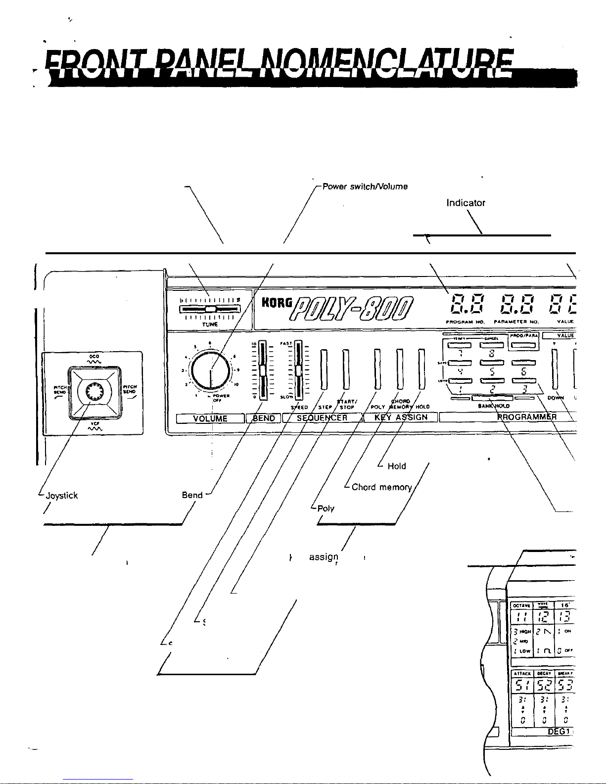
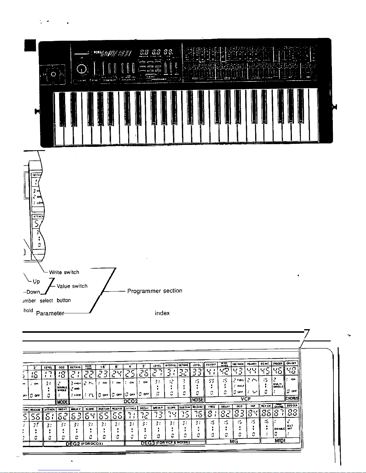
FRONT PANEL NOMENCLATURE
..............................................................................
6
.
REAR
PANEL
NOMENCLATURE
.................................................................................
6
l
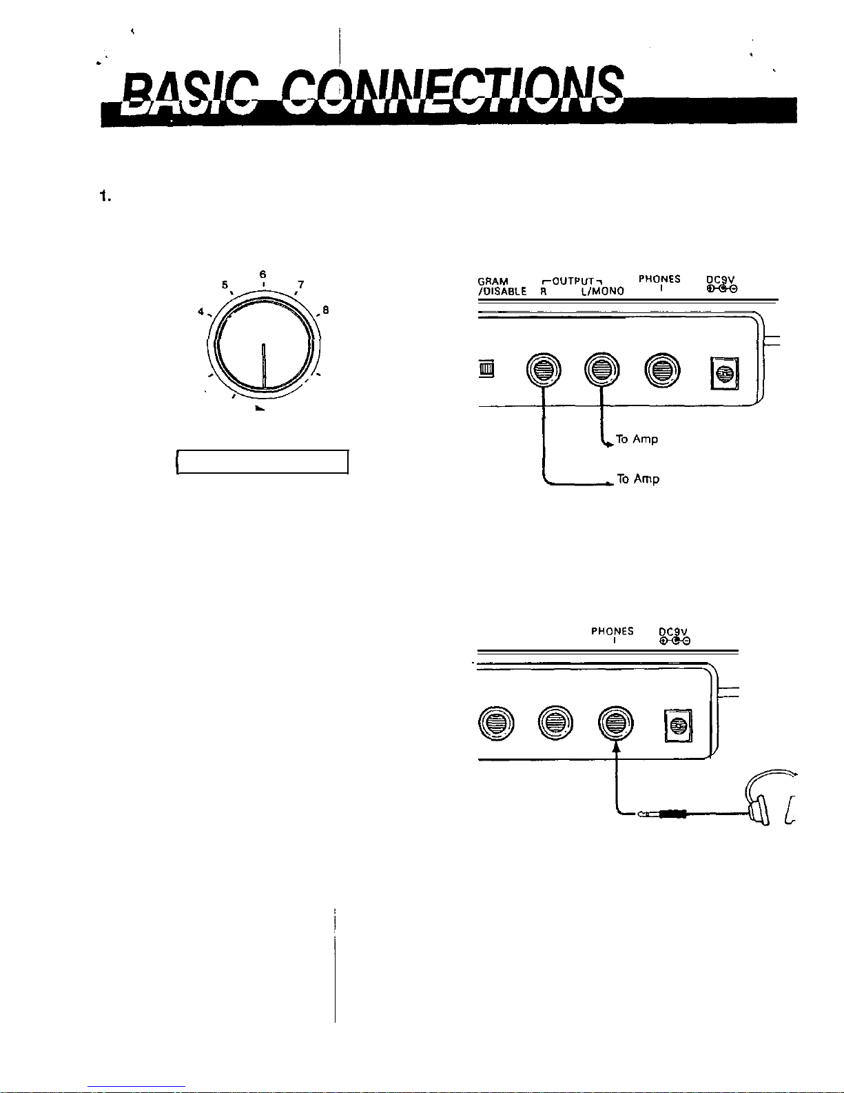
BASIC
CONNECTIONS
....................................................................................................
10
.FUNCTION AND OPERATIONS
....................................................................................
11
1.
2.
3.
4.
5.
6.
7.
8.
INITIAL SETUP
...............................................................................................................
11
SELECTING PROGRAMS
.............................................................................................
11
SOUND SYNTHESIS.....................................................................................................
13
3-I
What
is a
Synthesizer
.......................................................................................................
13
3.2
What is a Program
..........................................................................................................
13
3-3
Digital
access
control system..........................................................................................
13
3-4
Poly-800
Synthesizer Modules and Parameters
...............................................................
14
3.4.1.
DC0
1
......................................................................................................................
14
34.2. MODE
......................................................................................................................
15
3.4.3.
DCO
2
.............................
.
........................................................................................
16
3.4.4.
NOISE......................................................................................................................
16
3.4.5.
VCF..........................................................................................................................
17
3.4.6.
CHORUS
..................................................................................................................
18
3.4.7. DEG
..........................................................................................................................
19
3.4.a. MG
...........................................................................................................................
21
34.9. MIDI
..........................................................................................................................
21
CREATING SOUNDS.....................................................................................................
23
4-1l
Overview
.........................................................................................................................
23
4.2
Editing programs
............................................................................................................
23
4.3 Writing programs to memory
44 Moving programs
....
...................................................................................................................................................................................................
zz
PERFORMANCE FEATURES.......................................................................................
26
5.1
Tune
...............................................................................................................................
26
5.2
Joystick .....
5.3 Key assign mode
5.4
sequencer
................................................................................................................................................................................................................................................................Vìð}#çx¢Xï}¿2õ}02CV¯Œy¢Àñ}ä´¢H¯ ”Bä´
26
gi
5.5
Program Up
Footswitch
..................................................................................................
32
MUSICAL INSTRUMENT DIGITAL INTERFACE (MIDI)
.......................................
33
TAPE INTERFACE
.......................................................................................................... 35
7.1
Saving program and sequencer data on tape
,.,_._!
..........................................................
36
7.2 Recorded data tones
......................................................................................................
36
7-3
Verify
..............................................................................................................................
36
7-4
Loading data into the
Poly-8000
.........................................
~..................................
L..
.......
36
POWER SUPPLY............................................................................................................
40
8-l
Battery
,life
........
.
.....................................................................................................................................................................................................................
a-2 Replacing
batteries
ii
.
SPECIFCATIONS
,,,.,_,.,.,.,.,_~
..............................................................................................
41
l
OPTIONS
..............................................................................................
42
................................
.