Koyker KB75 User manual

PARTS MANUAL
KB75
BACKHOE
IMPORTANT-KOYKER DEALER
BE SURE THIS MANUAL IS GIVEN TO THE
PURCHASER FOR FUTURE REFERENCE
KOYKER MFG. CO., P.O. BOX 409,
LENNOX, SD 57039
Manual No: 677793 10/25/2005

Parts Manual
KB75
BACKHOE
IMPORTANT– KOYKER DEALER BE SURE THIS
MANUAL IS GIVEN TO THE PURCHASER FOR
FUTURE REFERANCE
KOYKER MFG. CO.,
P.O. BOX 409
LENNOX,SD 570 9
PHONE 1-800-456-1107 E-MAIL: KOKYKER@KOYKERMFG.COM
10/6/2005

CONTENTS
CONTENTS PAGE
KB75 Backhoe Parts Diagra ........................................................................................ 1
Parts Identification Schedule........................................................................................ 2-3
KB75 Hydraulic Syste Parts Identification Diagra .................................................. 4
KB60/KB75 Valve Control Diagra ............................................................................. 5
Valve Fitting Diagra .................................................................................................... 6
Draw Bar Bracket and 3 Point Stabilizer Kit Diagra .................................................. 7
Racine Six Section Valve Parts Diagra ....................................................................... 8
Racine Six Section Valve Parts Schedule.................................................................... 9-10
KB75 Independent Hydraulic Syste Parts Diagra ................................................... 11
KB75 Independent Hydraulic Syste Parts Schedule ............................................... 12-13
2 1/2” x 14” Dipper Cylinder Parts Diagra ................................................................ 14
2 1/2” x 10” Stabilizer Cylinder Parts Diagra ............................................................ 15
2 1/2” x 20” Boo Cylinder Parts Diagra .................................................................. 16
2 1/2” x 14” Bucket Cylinder Parts Diagra ................................................................ 17
2 1/2” x 10” Swing Cylinder Parts Diagra ................................................................. 18
Cylinder Warranty Infor ation..................................................................................... 19
Warranty Infor ation.................................................................................................... 20

KOYKER KB75 BACKHOE PARTS DIAGRAM
1

PARTS IDENTIFICATION SCHEDULE
KEY PART NUMBER DESCRIPTION QUANTITY
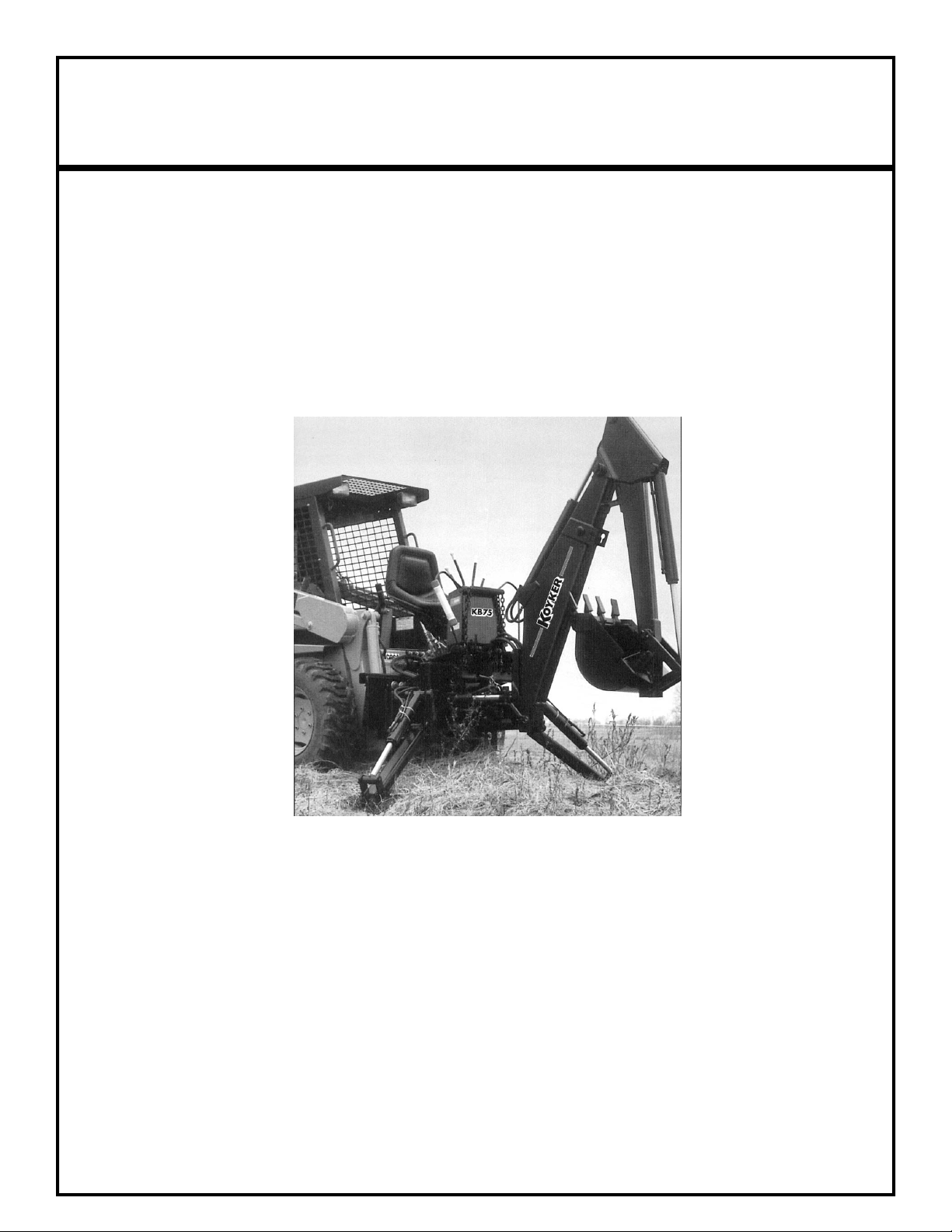
1............... 667200 ................. Main Fra e Weld Asse bly B750 ..................................................... 1
2............... 667201 ................. Swing Mast Weld Asse bly ............................................................... 1
3............... 667202 ................. Boo Weld Asse bly......................................................................... 1
4............... 667203 ................. Dipper Stick Weld Asse bly .............................................................. 1
5............... 667204 ................. Boo Lock .......................................................................................... 1
6............... 667205 ................. Stabilizer Ar (Standard).................................................................... 2
7............... 667206 ................. Stabilizer Pads ..................................................................................... 2
8............... 667207 ................. Bushing, 1-1/4” x 1”............................................................................ 6
9............... 667208 ................. Bushing, 1-1/4” x 1-1/2” ..................................................................... 2
10 ............. 660752 ................. Seat ...................................................................................................... 1
11 ............. 667217 ................. Stabilizer Cylinders ............................................................................. 2
12 ............. 667210 ................. Boo Cylinder .................................................................................... 1
13 ............. 667211 ................. Seat Base ............................................................................................. 1
14 ............. 677212 ................. Bucket Cylinder................................................................................... 1
15 ............. 667213 ................. Dipper Cylinder................................................................................... 1
16 ............. 667214 ................. Swing Cylinder Left Hand (standing behind achine designates left hand) ... 1
16 ............. 667214 ................. Swing Cylinder Right Hand (standing behind achine designates right hand)1
17 ............. 667215 ................. Bucket Link ......................................................................................... 1
18 ............. 667216 ................. Cylinder Link....................................................................................... 2
19 ............. 664417, 660792 ... Bucket 9”, 12” ..................................................................................... 1
19 ............. 660793, 660784 ... Bucket 15”, 18” ................................................................................... 1
20 ............. 664503 ................. Replaceable Tooth Point.......................................................................
20 ............. 667219 ................. Bucket Tooth Shank .............................................................................
20 ............. 667220 ................. Bucket Tooth Shank and Point.............................................................
21 ............. 667508 ................. Roll Pin, 5/16” x 2” ............................................................................. 4
22 ............. 667222 ................. 5/16” x 2” Bolt.................................................................................... 14
23 ............. 672223 ................. 5/16” Locknut..................................................................................... 14
24 ............. 667224 ................. 3/8” x 2-1/2” Bolt ................................................................................ 5
25 ............. 667282 ................. 3/8” Nut ............................................................................................... 5
26 ............. 667226 ................. Capscrew 1/2 x 3-1/2” ......................................................................... 1
NI............. 667410 ................. Locknut 1/2”........................................................................................ 1
35 ............. 666953 ................. Pin, 1” x 7” Swing Cylinder Base ....................................................... 2
36 ............. 667236 ................. Pin, 1” x 6-3/8” Swing Cylinder Rod................................................. 2
37 ............. 667237 ................. Pin, 1-1/4” x 5-1/4” Swing Pivot......................................................... 2
38 ............. 667238 ................. Pin, 1-1/4” x 8-1/8” Boo Pivot ......................................................... 1
39 ............. 667239 ................. Pin, 1” x 7-1/8” Boo Cylinder Rod End........................................... 1
40 ............ 667240 ................. Pin, 1” x 6-1/4” Boo Cyl Base, Dipper Cyl. Base, Stabilizer Pivot. 4
41 ............. 667242 ................. Pin, 1”-1/4” x 8-1/2” Dipper Pivot...................................................... 1
43 ............. 667243 ................. Pin, 1” x 8-1/8” Bucket Link............................................................... 1
44 ............. 667244 ................. Pin, 1-1/4” x 8-1/8 Bucket Pivot ......................................................... 1
45 ............. 667245 ................. Pin, 3/4” x 4-1/2” Stabilizer Cylinder Rod.......................................... 2
46 ............. 667246 ................. Pin, 3/4” x 5-1/4” Stabilizer Pad ......................................................... 2
47 ............. 667248 ................. Washer, 1-14/” I.D. ............................................................................. 2
48 ............. 667249 ................. Valve Cover......................................................................................... 1
49 ............. 667240 ................. Pin, 1” x 6-3/8” Stick base .................................................................. 1
50 ............. 667234 ................. Pin, 1” x 5-3/4”.................................................................................... 2
51 ............. 667221 ................. Roll Pin, 5/16” x 2-1/2”....................................................................... 1
2

PARTS IDENTIFICATION SCHEDULE CONT.
KEY PART NUMBER DESCRIPTION QUANTITY
NI............. 667247 ................. Pin, 7/8” x 4-3/8” Hitch....................................................................... 2
NI............. 667231 ................. Self-Tapping Screw ............................................................................. 4
NI............. 667232 ................. Hose Hold Down Cla p ..................................................................... 2
NI............. 666954 ................. Pins, 3/4” x 2-1/2” Drawbar ................................................................ 4
NI............. 666949 ................. Zerk Threaded 1/4”............................................................................. 28
NI............. 666950 ................. Zerk Threaded 90° 1/4”....................................................................... 2
3

HYDRAULIC SYSTEM PARTS DIAGRAM
KEY PART NUMBER DESCRIPTION QUANTITY
A.............. 667254 ................. Hose, 8P-50” 8JFS Pressure “Red Tip” .............................................. 1
B.............. 667255 ................. Hose, 4P2-102” 6JFS-6JFS Stick Pivot............................................... 1
C.............. 665630 ................. Hose, 6P2-85” 6JFS-6JFS Stick.......................................................... 1
D.............. 667257 ................. Hose, 6P-115” 6JFS-6JFS Bucket....................................................... 1
E............... 667258 ................. Hose, 4P-119” 6JM-6JFS Bucket........................................................ 1
G.............. 667260 ................. Hose, 4P-46” 6JFS-6JFS Stabilizer..................................................... 2
H.............. 667261 ................. Hose, 4P-42” 6JFS-6JFS Stabilizer..................................................... 2
J&K.......... 667263 ................. Hose, 4P-29” 6FJS-6JFS Swing.......................................................... 2
L............... 667266 ................. Hose, 4P2-64” 6JM-6JFS Boo ......................................................... 1
M.............. 677265 ................. Hose, 6P2-65” 6JM-6JFS Boo ......................................................... 1
N.............. 667267 ................. Hose, 4P-16” 6JFS-6JFS ..................................................................... 1
O.............. 667254 ................. Hose, 8P-50” 8JFS Return “Blue Tip”................................................ 1
1............... 667587 ................. 863B x 6 Elbow................................................................................... 2
................. 667586 ................. LH Manifold Cushion (old style prior to 10-01-99 not shown) .................... 1
................. 667585 ................. RH Manifold Cushion (old style prior to 10-01-99 not shown) .................... 1
NOTE: New Style Swing Manifolds rigidly secured to Barrel Asse .
4............... 668246 ................. Swing Cylinder (old style prior to 10-01-99)............................................. 2
4............... 668245 ................. LH Swing Cylinder (units fg after 10-01-99).......................................... 1
4............... 667214 ................. RH Swing Cylinder (units fg after 10-01-99) ......................................... 1
5............... 667588 ................. 853B x 6 Elbow................................................................................... 2
4

KB60 AND KB75 VALVE CONTROL DIAGRAM
KEY PART NUMBER DESCRIPTION QUANTITY
1............... 667269................. Main Control Base .............................................................................. 1
2............... 665609................. Main Control Lever............................................................................. 2
3............... 667270................. Short Spherical Link ........................................................................... 1
4............... 667271................. Long Spherical Link ........................................................................... 1
5............... 667272................. .3/8 N.F. Ja Nu .............................................................................. 1
6............... 665624................. Main Control Lock Collar................................................................... 2
7............... 667273................. L.H. Control Trunion .......................................................................... 1
8............... 667274................. R.H. Control Trunion.......................................................................... 1
9............... 667275................. Adjustable Control Links.................................................................... 2
10............. 665610................. Stabilizer Control Levers .................................................................... 2
11............. 667277................. Shoulder Bolt 5/16” x 7/8” ................................................................. 2
12............. 667278................. 5/16” N.C. Nut .................................................................................... 2
13............. 667279................. 1/4” x 3/4” Clevis Pin ......................................................................... 4
14............. 667577................. Plastic Knobs ...................................................................................... 4
15............. 667280................. 3/8” x 1-1/2” Carriage Bolts ............................................................... 3
16............. 667281................. 3/8” Flat Washer ................................................................................. 6
17............. 667282................. 3/8” N.C. Nuts..................................................................................... 6
18............. 667283................. Fe ale Spool End ............................................................................... 4
19............. 664714................. Plastic Control Cover.......................................................................... 1
NI ............ 667284................. Cotter 1-16” x 3/4”.............................................................................. 4
NI ............ 667231................. Self-Tapping Screws........................................................................... 2
5

VALVE FITTING DIAGRAM
KEY PART NUMBER DESCRIPTION QUANTITY
1............... 667250 ................. 850 x 6 x 8 Straight Thread O-Ring Connector ................................. 12
2............... 667251 ................. 8538 x 8 x 10 Straight Thread O-Ring 90° Elbow .............................. 1
3............... 667252 ................. Power Beyond Sleeve.......................................................................... 1
4............... 667253 ................. 8508 x 8 x 10 Straight Thread O-Ring Connector .............................. 2
6

DRAW BAR BRACKET AND 3-PT STABILIZER KIT DIAGRAM
KEY PART NUMBER DESCRIPTION QUANTITY
1............... 667287 ................. Draw Bar Bracket ................................................................................ 1
2............... 667288 ................. U-Bolt 5/8” x 2-1/2” x 2-3/4”............................................................. 2
3............... 667289 ................. Spacer Bar ........................................................................................... 2
4............... 667290 ................. Adjustable Stabilizer Linkage CAT I .................................................. 2
5............... 667291 ................. 3/4” x 4-1/2” Pins w/Handle Loop ...................................................... 5
6............... 667292 ................. 1/4” Lynch Pins ................................................................................... 5
7............... 667247 ................. 7/8” x 4-1/2” Hitch Pin w/ Handle ...................................................... 2
8............... 664529 ................. Locking Bar Asse bly KB75 ............................................................. 1
9............... 665643 ................. Eyebolt 3/4” x 7”................................................................................. 2
10 ............. 667298 ................. 3/4” Nut ............................................................................................... 2
11 ............. 667299 ................. 3/4” Ja Nut........................................................................................ 2
12 ............. 667319 ................. 3/4” Lock Washer................................................................................ 2
NI............. 667293 ................. 5/8” x 3-1/2” Capscrews...................................................................... 1
NI............. 667294 ................. 3/4” x 3-1/2” Capscrews...................................................................... 1
NI............. 667295 ................. 5/8” Flat Washer.................................................................................. 1
NI............. 667296 ................. 5/8” Nuts.............................................................................................. 5
NI............. 667297 ................. 5/8” Ja Nuts ...................................................................................... 5
NI............. 667298 ................. 3/4” Nut ............................................................................................... 1
NI............. 667299 ................. 3/4” Ja Nut........................................................................................ 1
7

RACINE SIX SECTION VALVE PARTS DIAGRAM
8

RACINE SIX SECTION VALVE SCHEDULE
KEY PART NUMBER DESCRIPTION QUANTITY
1............... 667300 ................. #10 S.A.E Plug Asse bly ................................................................... 2
2............... 667301 ................. Outlet Manifold Section with #10 ....................................................... 1
3............... 667302 ................. Valve Section With #8 Opening.......................................................... 5
4............... 667283 ................. Fe ale Spool End................................................................................ 6
5............... 667304 ................. Inlet Manifold Section with #10.......................................................... 1
6............... 667305 ................. Direct Relief Valve Cartridge.............................................................. 1
7............... 667306 ................. O-Ring ................................................................................................. 1
8............... 667307 ................. Poppet.................................................................................................. 1
9............... 667308 ................. Poppet Body ........................................................................................ 1
10 ............. 667309 ................. O-Ring ................................................................................................. 2
11 ............. 667310 ................. Spring .................................................................................................. 1
12 ............. 667311 ................. O-Ring ................................................................................................. 1
13 ............. 667312 ................. Direct Relief Valve Cartridge Body .................................................... 1
14 ............. 667313 ................. Spring Seat........................................................................................... 1
15 ............. 667314 ................. Adjustable Screw................................................................................. 1
16 ............. 667315 ................. Ja Nut................................................................................................ 1
17 ............. 667316 ................. Back-Up Ring...................................................................................... 1
24 ............. 667317 ................. Screw .................................................................................................. 12
25 ............. 667318 ................. Spool End ............................................................................................ 6
26 ............. 667320 ................. Spacer .................................................................................................. 6
27 ............. 667321 ................. Cover ................................................................................................... 6
28 ............. 667322 ................. Spring Retainer................................................................................... 11
29 ............. 667323 ................. Spring .................................................................................................. 6
30 ............. 667324 ................. O-Ring ................................................................................................. 1
31 ............. 667325 ................. Back-Up Ring...................................................................................... 1
32 ............. 667326 ................. O-Ring ................................................................................................. 1
33 ............. 667252 ................. Power Beyond Sleeve.......................................................................... 1
34 ............. 667309 ................. O-Ring ................................................................................................. 1
35 ............. 667328 ................. #8 Plug................................................................................................. 1
36 ............. 667329 ................. O-Ring ................................................................................................ 12
37 ............. 667330 ................. O-Ring ................................................................................................. 6
37 ............. 667331 ................. O-Ring ................................................................................................ 12
39 ............. 667332 ................. O-Ring ................................................................................................. 6
40 ............. 667333 ................. Load Check Piston............................................................................... 6
41 ............. 667334 ................. Spring .................................................................................................. 6
42 ............. 667326 ................. O-Ring ................................................................................................. 6
43 ............. 667335 ................. Plug...................................................................................................... 6
44 ............. 667336 ................. Load Check Asse bly......................................................................... 6
45 ............. 667337 ................. Tie Rod Nut ......................................................................................... 6
46 ............. 666955 ................. Tie Rod Lockwasher............................................................................ 6
47 ............. 667338 ................. Tie Rod ................................................................................................ 3
48 ............. 667339 ................. Boo Section w/Float Position........................................................... 1
9

RACINE SIX SECTION VALVE SCHEDULE CONT.
KEY PART NUMBER DESCRIPTION QUANTITY
49 ............. 667340 ................. Valve Body.......................................................................................... 1
50 ............. 667341 ................. Spool Float-Boo Spool Only ............................................................ 1
52 ............. 667342 ................. Spring Retainer.................................................................................... 1
53 ............. 667343 ................. Spool End Float ................................................................................... 1
54 ............. 667344 ................. Ball, Detent.......................................................................................... 2
55 ............. 667345 ................. Spring, Detent...................................................................................... 2
56 ............. 667346 ................. Screw, Allen Head............................................................................... 2
57 ............. 667347 ................. Lower Extension.................................................................................. 1
58 ............. 667348 ................. Screw, Allen Head............................................................................... 2
59 ............. 667349 ................. Nut ....................................................................................................... 2
60 ............. 667349 ................. 1/4”-28 Ja Nut .................................................................................. 1
61 ............. 667348 ................. 1/4”-28 Spool Li it Adj. Screw.......................................................... 1
NI............. 664542 ................. Spool-Standard .................................................................................... 5
10

KB75 INDEPENDENT HYDRAULIC SYSTEM PARTS DIAGRAM
11

KB75 INDEPENDENT HYDRAULIC SYSTEM PARTS SCHEDULE
660788 540 RPM SYSTEM
KEY PART NUMBER DESCRIPTION QUANTITY
1............... 667350 ................. KB75 Oil Reservoir............................................................................. 1
1............... 667351 ................. Filter Screen......................................................................................... 1
3............... 667352 ................. Street EL 1” 90° .................................................................................. 1
4............... 667598 ................. Hose Barb 1” ....................................................................................... 1
5............... 667354 ................. 1” Hose Cla p .................................................................................... 1
6............... 663905 ................. 16CBW-12JFS-0-50” Hose................................................................. 1
7............... 667355 ................. 6400-20-12 Pu p Adapter (Suction) .................................................. 1
8............... 667356 ................. 388K Webster Pu p (Rear Port)........................................................ 1
9............... 667357 ................. 6410 x 16 x 12 Pu p Adapter (Pressure)............................................ 1
10 ............. 667358 ................. 6900 x 12 x 8 Pu p Fitting (Pressure)................................................ 1
11 ............. 667359 ................. Torque Bar for 388K Pu p................................................................. 1
12 ............. 667360 ................. 9405 x 8 x 8 Swivel Nut EL ................................................................ 1
13 ............. 667361 ................. Pu p Drive Adapter 1-3/8” x 1” Bore................................................ 1
14 ............. 667362 ................. Breather Cap........................................................................................ 1
15 ............. 667254 ................. Backhoe Pressure & Return Hoses...................................................... 2
16 ............. 666951 ................. 3/4” x 10” Rubber Hose Cover............................................................ 2
NI............. 667364 ................. 1/2” x 2” NC Capscrews...................................................................... 2
NI............. 667365 ................. 5/16” x 1” NC Capscrews.................................................................... 4
NI............. 667366 ................. 1/2” NC Nuts ....................................................................................... 2
NI............. 667367 ................. 1/2” Star Washers ................................................................................ 4
NI............. 667278 ................. 5/16” NC Nuts ..................................................................................... 2
NI............. 667369 ................. 5/16” Lock Washers ............................................................................ 4
NI............. 667404 ................. Drain Plug 3/8”.................................................................................... 1
12

KB75 INDEPENDENT HYDRAULIC SYSTEM PARTS SCHEDULE
660757 1000 RPM SYSTEM
KEY PART NUMBER DESCRIPTION QUANTITY
1............... 667350 ................. KB75 Oil Reservoir............................................................................. 1
1............... 667351 ................. Filter Screen......................................................................................... 1
3............... 667352 ................. 1” ST EL.............................................................................................. 1
4............... 667598 ................. Hose Barb 1” ....................................................................................... 1
5............... 667354 ................. 1” Hose Cla p .................................................................................... 1
6............... 663905 ................. Hose 16CBW-12JFS-0-50” ................................................................. 1
12 ............. 667360 ................. Adapter 9405 8 x 8 .............................................................................. 1
14 ............. 667362 ................. Breather Cap........................................................................................ 1
15 ............. 667254 ................. Backhoe Pressure & Return Hoses...................................................... 2
16 ............. 666951 ................. 3/4” x 10” Rubber Hose Cover............................................................ 2
17 ............. 667371 ................. Torque Bar For 194YC Pu p ............................................................. 1
18 ............. 667400 ................. 194YC Webster Pu p (Rear Ports) .................................................... 1
19 ............. 667401 ................. Pu p Drive Adapter 1-3/8 x 3/4” Bore............................................... 1
20 ............. 666956 ................. 6400-12-14 Pu p Adapter Suction..................................................... 1
21 ............. 667370 ................. 6900-10-8 Pu p Adapter Pressure...................................................... 1
NI............. 667373 ................. 3/8” x 1-1/4” NC Capscrews ............................................................... 2
NI............. 667365 ................. 5/16” x 1” NC Capscrews.................................................................... 4
NI............. 667282 ................. 3/8” NC Nuts ....................................................................................... 2
NI............. 667278 ................. 5/16” NC Nuts ..................................................................................... 4
NI............. 667375 ................. 3/8” Star Washers ................................................................................ 2
NI............. 667369 ................. 5/16” Lock Washers ............................................................................ 4
NI………. 667404…………. Drain Plug 3/8”……………………………………………………….1
NI............. 667404 ................. Drain Plug 3/8”.................................................................................... 1
13

2-1/2” x 14” DIPPER CYLINDER PARTS DIAGRAM
KEY PART NUMBER DESCRIPTION QUANTITY
1............... 667376................. Barrel Asse bly.................................................................................. 1
2............... 667377................. Capscrew, 7/8”.................................................................................... 1
3............... 667378................. Dyna Seal, 7/8” ................................................................................... 1
4............... 667379................. Piston................................................................................................... 1
5............... 667380................. Piston Seal........................................................................................... 1
6............... 667381................. Internal Lock Washer.......................................................................... 1
7............... 667382................. Cylinder Head ..................................................................................... 1
8............... 667383................. Back-Up Ring ..................................................................................... 1
9............... 667384................. O-Ring................................................................................................. 1
11............. 667385................. Lockwire ............................................................................................. 1
12............. 667386................. Rod Seal .............................................................................................. 1
13............. 667387................. Rod Wiper........................................................................................... 1
14............. 666957................. Rod Asse bly..................................................................................... 1
NI ............ 667389................. Seal Kit................................................................................................ 1
Part No. 667213
14

2-1/2” x 10” STABILIZER CYLINDER PARTS DIAGRAM
Part No. 667217
KEY PART NUMBER DESCRIPTION QUANTITY
1............... 667390................. Barrel Asse bly.................................................................................. 1
2............... 667377................. Capscrew, 7/8...................................................................................... 1
3............... 667378................. Dyna Seal, 7/8..................................................................................... 1
4............... 667379................. Piston................................................................................................... 1
5............... 666958................. Piston Seal Polypack........................................................................... 1
6............... 667381................. Internal Lock Washer.......................................................................... 1
7............... 667382................. Cylinder Head ..................................................................................... 1
8............... 667383................. Back-Up Ring ..................................................................................... 1
9............... 667384................. O-Ring................................................................................................. 1
11............. 667385................. Lockwire ............................................................................................. 1
12............. 667386................. Rod Seal .............................................................................................. 1
13............. 667387................. Rod Wiper........................................................................................... 1
14............. 667391................. Rod Asse bly..................................................................................... 1
NI ............ 666959................. Seal Kit Polypack................................................................................ 1
15

2-1/2” X 20” BOOM CYLINDER PARTS DIAGRAM
KEY PART NUMBER DESCRIPTION QUANTITY
1............... 667392................. Barrel Asse bly.................................................................................. 1
2............... 667377................. Capscrew, 7/8”.................................................................................... 1
3............... 667378................. Dyna Seal, 7/8” ................................................................................... 1
4............... 667379................. Piston................................................................................................... 1
5............... 667380................. Piston Seal........................................................................................... 1
6............... 667381................. Internal Lock Washer.......................................................................... 1
7............... 667382................. Cylinder Head ..................................................................................... 1
8............... 667383................. Back-Up Seal ...................................................................................... 1
9............... 667384................. O-Ring................................................................................................. 1
11............. 667385................. Lockwire ............................................................................................. 1
12............. 667386................. Rod Seal .............................................................................................. 1
13............. 667387................. Rod Wiper........................................................................................... 1
14............. 667393................. Rod Asse bly..................................................................................... 1
NI ............ 667389................. Seal Kit................................................................................................ 1
Part No. 667210
16

2-1/2” X 14” BUCKET CYLINDER PARTS DIAGRAM
Part No. 667212
KEY PART NUMBER DESCRIPTION QUANTITY
1............... 667394................. Barrel Asse bly...................................................................................
2............... 667377................. Capscrew, 7/8”.................................................................................... 1
3............... 667378................. Dyna Seal, 7/8” ................................................................................... 1
4............... 667379................. Piston................................................................................................... 1
5............... 667380................. Piston Seal........................................................................................... 1
6............... 667381................. Internal Lock Washer.......................................................................... 1
7............... 667382................. Cylinder Head ..................................................................................... 1
8............... 667383................. Back-Up Ring ..................................................................................... 1
9............... 667684................. O-Ring................................................................................................. 1
11............. 667385................. Lockwire ............................................................................................. 1
12............. 667386................. Rod Seal .............................................................................................. 1
13............. 667387................. Rod Wiper........................................................................................... 1
14............. 667395................. Rod Asse bly..................................................................................... 1
NI ............ 667389................. Seal Kit................................................................................................ 1
17
Table of contents
Other Koyker Tractor Accessories manuals