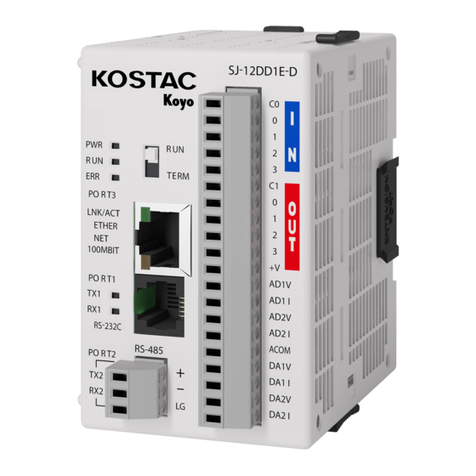
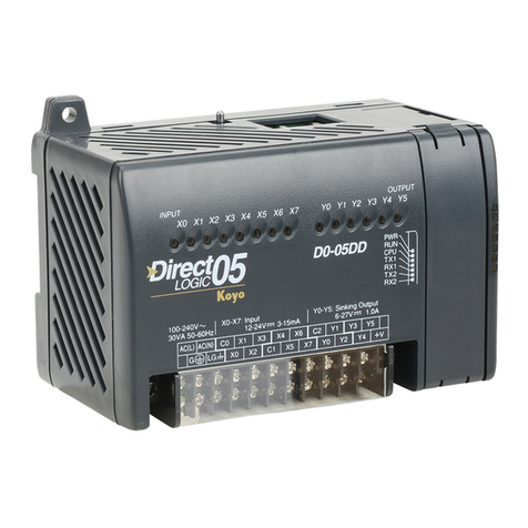
Koyo NK1 Series User manual

Value & Technology
NK1 Series PLC Manual
NK1-B4AD2DA-2 Function Board
[1st Edition]
KOYO ELECTRONICS (WUXI) CO., LTD.

1
Contents
Chapter 1 Preface......................................................................................................1
Chapter 2 NK1-B4AD2DA-2 Specifications.............................................................2
2.1 Introduction......................................................................................................2
2.2 General Specifications ..................................................................................2
2.3 Input Specifications ......................................................................................3
2.4 Output Specifications ....................................................................................3
2.5 Wiring .................................................................................................................3
2.5.1 Wiring Guidelines ..................................................................................3
2.5.2 Wiring Diagram ........................................................................................4
2.6 Registers Used by NK1-B4AD2DA-2.................................................................4
2.6.1 Analog Input Registers.........................................................................5
2.6.2 Analog Output Registers.......................................................................5
2.6.3 Module Resolution ..................................................................................6

1
Chapter 1 Preface
Thank you for purchasing our company's NK1 series PLC products!
This document is technical information about optional function boards NK1-B4AD2DA-2
used with NK1 series PLC. It mainly introduces the hardware specifications, hardware
performance, software settings, external wiring of this function board. When using this
technical information, please refer to other user manuals, instruction manuals and other
materials related to NK1 in order to obtain comprehensive and complete usage information
of the product.
It supports the installation of a backup lithium battery for calendar and clock,
but the backup lithium battery is not provided at the factory. If you need backup lithium
battery, please purchase separately. Model is RB-50.
For the installation and removal of the option function board, please refer to the
relevant chapter in the NK1 User Manual.
Note: Only NK1-CPU40 * sub-series products support the installation of option
function boards; NK1-CPU20 * sub-series and NK1L series products do not support the
installation of option function boards.
When using our products, if you have any question, please contact our local offices
or contact us directly.
Modification History
Name:NK1 Series PLC Optional Function Board Manual
No.
Data
Description of Changes
KEW-M2523A-2
2015.12
Original Edition
Note: KEW-M2523A-1: The document for NK1-B08CDT1 board
KEW-M2523A-2: The document for NK1-B4AD2DA-2 board
If you need to contact us about this manual, please first determine the version
number of the manual!

2
Chapter 2 NK1-B4AD2DA-2 Specifications
2.1 Introduction
NK1-B4AD2DA-2 is an analog voltage input
/output optional function board for NK1 series
PLC. The voltage range is 0-10V. The function
board has 12-bit resolution. It has non-
isolated 4 analog input channels and 2 analog
output channels.
The main features of this optional function
board are as follows:
The resolution of analog input is 12 bit.
The resolution of analog output is 12
bit.
No external power supply required.
With OK indicator (green),it will be on
during normal work.
2.2 General Specifications
Item
Specifications
Dimensions(mm)
47.2L×53.0W ×18.69H
Weight
21g
Storage Temperature
-40~70 ℃
Operating Temperature
0~55 ℃
Relative Humidity
30%~95%(non-condensing)
Environmental Air
No corrosive gases permitted
Vibration/Shock
Same as NK1 main unit
Optional Battery
(not included)
RB-50,for calendar & clock of main unit

2.3 Input Specifications
Number of Input Channels
4
Range
0-10V
Resolution
12 bit
Input Impedance
1MΩ±5%
PLC Update Rate
4 input channels per scan
Conversion Method
Successive approximation
Isolation Type
None
Maximum Error
±0.3% of full scale
2.4 Output Specifications
Number of Output Channels
2
Range
0-10V
Resolution
12 bit
Load Impedance
Minimum 2000Ω
PLC Update Rate
2 output channels per scan
Isolation Type
None
Maximum Error
±1.0% of full scale
2.5 Wiring
2.5.1 Wiring Guidelines
Your company may have guidelines for wiring and cable installation. If so, check
the guidelines before beginning the installation. Here are some general things to
consider:
1
、Use the shortest wiring route whenever possible.
2、
Wire strictly according to the label on the terminal, do not mix the wires of different
channels to avoid interference.
3、Do not run the signal wiring next to large motors, high current switches, or
transformers. This may cause noise problems.
4、
Users can choose the wiring method that suits them, but all wiring must meet the safety
requirements to avoid accidental danger.

2.5.2 Wiring Diagram
Note:
1、
Do not mix the wires of different channels
to avoid interference.
2、Connect the unused ADn to SG to avoid
interference.
3、All SG terminals are internally
connected.
ADn represents input channels AD1,AD2,
AD3,and AD4.
2.6 Registers Used by NK1-B4AD2DA-2
The use of the optional function board does not require any settings, as long as
the unit is installed on the NK1 series PLC (for specific installation methods, please
refer to the chapter about the optional function board in the "NK1 User Manual"), you
can read or write the relevant registers directly through the program to implement the
analog input and output functions. The registers used by this option function board
are shown in the following table.
NK1-B4AD2DA-2(0-10V)
Channel
Register
Analog Input
AD1
R37420
AD2
R37421
AD3
R37422
AD4
R37423
Analog Output
DA1
R37424
DA2
R37425
Note:After the optional function board is installed on the NK1 series PLC, the registers
listed in the table above are provided for the exclusive use of the optional
function board. Please do not use these registers for other purposes in the user
system.

The option function board does not occupy the normal I / O points.
The following describes The registers used by the analog input / output of this option
function board are described as follow.
2.6.1 Analog Input Registers
This optional function board has 4 analog input channels. Each channel has its
designated R register to store the digital conversion data (HEX) of the analog voltage
value from the corresponding input terminal. The input registers corresponding to its
input channels: AD1 –R37420, AD2 –R37421, AD3 –R37422, and AD4 –R37423. The
format of the conversion data is as follows:
Bit
15
14
13
12
11
10
9
8
7
6
5
4
3
2
1
0
0
0
0
0
*
*
*
*
*
*
*
*
*
*
*
*
The range of conversion data is 0 ~ 0x0FFF.
Note: Please do not apply voltage signals other than 0-10V to the input terminal
of this function board, otherwise the option function board and NK1 series PLC main
unit may be damaged.
2.6.2 Analog Output Registers
This option function board has 2 analog output channels, and each analog output
channel has its designated R register for setting the analog value (HEX) . When a value
is set in this register, this function board automatically outputs a 0-10V voltage signal
corresponding to the set value at the corresponding analog output terminal.
The setting registers corresponding to the output channels: DA1 –R37424 and DA2
- R37425. The format of its analog output setting data is as follows:
bit
15
14
13
12
11
10
9
8
7
6
5
4
3
2
1
0
*
*
*
*
*
*
*
*
*
*
*
*
Note: The valid setting range of the output analog data is 0 ~ 0xFFF; if the setting
data is greater than 0xFFF, the system automatically intercepts the valid part of
the setting value.

2.6.3 Module Resolution
0 3FF(H)7FF(H)BFF(H)FFF(H)
(0)(1023)(2047)(3071)(4095)
(0V)
(2.5V)
(5V)
(7.5V)
(10V)
Analog value
Digital value

Koyo
ELECTRONICS (WUXI)CO., LTD.
Add:21st Floor, Building 1, No.599, Jianzhuxi Road
Binhu District, Wuxi, Jiangsu, P.R. China
Pc:214072
Tel:0510-85167888 Fax:0510-85161393
http: //www.koyoele.com.cn
KEW-M2523A-2
2020 年1月
This manual suits for next models
1
Table of contents
Other Koyo Controllers manuals
Popular Controllers manuals by other brands

AGPtek
AGPtek HA0278 user manual

Grundfos
Grundfos Conex DIA-1 Installation and operating instructions

G-Systems
G-Systems GSE AC-EC user manual

NXP Semiconductors
NXP Semiconductors MC13224V user guide

Planet Networking & Communication
Planet Networking & Communication WAPC-500 Configuration guide

ABB
ABB M2301 manual

Samson
Samson 3271 Mounting and operating instructions

GYS
GYS NOMAD POWER PRO 12XL manual

Sutter Instrument
Sutter Instrument MP-285A Basic operations

Festo
Festo SFC-LAC-IO Series Brief overview

Franklin Electric
Franklin Electric SmartStart SSP1E-30S owner's manual

AudioCodes
AudioCodes RX-PAD User's and Administrator's manual