manuals.online logo
Brands
  1. Home
  2. •
  3. Brands
  4. •
  5. Kraga
  6. •
  7. Toy
  8. •
  9. Kraga Maripi User manual

Kraga Maripi User manual

Other Kraga Toy manuals

Kraga Roa II User manual

Kraga

Kraga Roa II User manual

Kraga Kodo User manual

Kraga

Kraga Kodo User manual

Popular Toy manuals by other brands

FUTABA GY470 instruction manual

FUTABA

FUTABA GY470 instruction manual

LEGO 41116 manual

LEGO

LEGO 41116 manual

Fisher-Price ColorMe Flowerz Bouquet Maker P9692 instruction sheet

Fisher-Price

Fisher-Price ColorMe Flowerz Bouquet Maker P9692 instruction sheet

Little Tikes LITTLE HANDIWORKER 0920 Assembly instructions

Little Tikes

Little Tikes LITTLE HANDIWORKER 0920 Assembly instructions

Eduard EF-2000 Two-seater exterior Assembly instructions

Eduard

Eduard EF-2000 Two-seater exterior Assembly instructions

USA Trains EXTENDED VISION CABOOSE instructions

USA Trains

USA Trains EXTENDED VISION CABOOSE instructions

Modellbau Laffont Z1601 Assembly instructions

Modellbau Laffont

Modellbau Laffont Z1601 Assembly instructions

NOCH 12905 instruction manual

NOCH

NOCH 12905 instruction manual

Eduard Ki-61-Id quick start guide

Eduard

Eduard Ki-61-Id quick start guide

Viessmann Vollmer 45616 Mounting instruction

Viessmann

Viessmann Vollmer 45616 Mounting instruction

Vollmer 42004 Mounting instruction

Vollmer

Vollmer 42004 Mounting instruction

Phoenix Model CLASSIC-EP instruction manual

Phoenix Model

Phoenix Model CLASSIC-EP instruction manual

H-KING Sopwith Camel British WW1 Fighter instruction manual

H-KING

H-KING Sopwith Camel British WW1 Fighter instruction manual

MODSTER Predator 4x4 Crawler user manual

MODSTER

MODSTER Predator 4x4 Crawler user manual

DHK Hobby 8136 User instruction manual

DHK Hobby

DHK Hobby 8136 User instruction manual

THUNDER TIGER Raptor 50 V2 kit manual

THUNDER TIGER

THUNDER TIGER Raptor 50 V2 kit manual

Timberkits Skateboarder instructions

Timberkits

Timberkits Skateboarder instructions

Hangar 9 Funtana 125 Assembly manual

Hangar 9

Hangar 9 Funtana 125 Assembly manual

manuals.online logo
manuals.online logoBrands
  • About & Mission
  • Contact us
  • Privacy Policy
  • Terms and Conditions

Copyright 2025 Manuals.Online. All Rights Reserved.

Maripi build guide 1.3
Please do not share files that you bought
Development of a new plane and support of the old ones is very time consuming. Only with your
help I can focus fully on this project and spend some quality time with my family.
support@kragamodels.com
6 7 658
64
26
10
24
25
23
22
9
27
80
14
62
66
63
5
48
49
50
28
51
53
41
78
40
82
52
33
323130432987
70
74
88
84
1
11
3
85
86
2
72
4
71
77
45
12
34
35
81
38
39
37
58
59
36
57 56 55 54 13
67
47
46
79
61
75
76
83
73
60
42
44
21
20
19
18
16
17
15
69
68
ITEM NO.
PART NAME
PRINT AS
QTY.
1
fuse_0_SK3_35xx
SOLID
1
2
fuse_1
SOLID
1
3
fuse_2
SOLID
1
4
fuse_3
SOLID
1
5
fuse_4
SOLID
1
6
fuse_5
SOLID
1
7
fuse_6
SOLID
1
8
fuse_7
SOLID
1
9
fuse_8
SOLID
1
10
fuse_9
SOLID
1
11
canopy_front
SOLID
1
12
canopy_middle_0
SOLID
1
13
canopy_middle_1
SOLID
1
14
canopy_tail
SOLID
1
15
servo_plate_hs_65
SOLID
1
16
fuse_servo_plate_spar_2x1_68
-
1
17
fuse_servo_plate_spar_back_2x1_51
-
1
18
tail_leg_spar_2x1_80
-
1
19
ver_stab_main_b_spar_2x1_80
-
1
20
ver_stab_main_f_spar_2x1_97
-
1
21
ver_stab_mov_spar_2x1_165
-
1
22
ver_stab_b_0
SHELL
1
23
ver_stab_b_1
SHELL
1
24
ver_stab_b_2
SHELL
1
25
ver_stab_f_0
SHELL
1
26
ver_stab_f_1
SHELL
1
27
ver_stab_horn
SOLID
1
28
wing_L_0
SHELL
1
29
wing_L_1
SHELL
1
30
wing_L_2
SHELL
1
31
wing_L_3
SHELL
1
32
wing_L_4
SHELL
1
33
wing_L_5
SHELL
1
34
wing_R_0
SHELL
1
35
wing_R_1
SHELL
1
36
wing_R_2
SHELL
1
37
wing_R_3
SHELL
1
38
wing_R_4
SHELL
1
39
wing_R_5
SHELL
1
40
back_wing_spar_2x1_245
-
2
41
main_wing_spar_6x4_454
-
4
42
servo_mount_wing_L_B
SOLID
1
43
servo_mount_wing_L_F
SOLID
1
44
servo_mount_wing_R_B
SOLID
1
45
servo_mount_wing_R_F
SOLID
1
46
wing_hook_L
SOLID
1
47
wing_hook_R
SOLID
1
48
aileron_L_0
SHELL
1
49
aileron_L_1
SHELL
1
50
aileron_L_2
SHELL
1
51
aileron_L_3
SHELL
1
52
aileron_L_4
SHELL
1
53
aileron_L_5
SHELL
1
54
aileron_R_0
SHELL
1
55
aileron_R_1
SHELL
1
56
aileron_R_2
SHELL
1
57
aileron_R_3
SHELL
1
58
aileron_R_4
SHELL
1
59
aileron_R_5
SHELL
1
60
aileron_spar_2x1_436
-
2
61
hor_stab_ctrl_arm
SOLID
1
62
hor_stab_L_0
SHELL
1
63
hor_stab_L_1
SHELL
1
64
hor_stab_R_0
SHELL
1
65
hor_stab_R_1
SHELL
1
66
hor_stab_control_spar_2x1_284
-
1
67
hor_stab_pivot_spar_3_284
-
1
68
hor_stab_inner_endcap_L
SOLID
1
69
hor_stab_inner_endcap_R
SOLID
1
70
shoe_L
SOLID
1
71
shoe_R
SOLID
1
72
landing_leg_spar_3_145
-
2
73
wheel_shaft_23
-
2
74
wheel_45
-
2
75
aileron_horn_L
SOLID
1
76
aileron_horn_R
SOLID
1
77
servo_common
-
2
78
aileron_endcap_L
SOLID
1
79
aileron_endcap_R
SOLID
1
80
ver_stab_endcap
SOLID
1
81
wing_L_endcap
SOLID
1
82
wing_R_endcap
SOLID
1
83
hinge
-
11
84
landing_leg_back_spar_3_161
-
2
85 fuse_spar_2x1_8582
-
2
86 fuse_spar_2x1_8622
-
2
87
wing_joiner_rod_4_280
-
1
88
wing_joiner_rod_4_300
-
1
KRAA MARIPI
Printing
You need to use two printing methods to print all parts:
1. Solid parts (fuse and accessories - all grey parts). Use dense (100%)
infill. This is common way of printing objects and these parts should
be printable on every printer.
2. Shell parts (wings - all red parts). Use 0% infill and no
horizontal surfaces (thickness of the shell is one layer).
Only this way you can achieve required weight of the
plane.
You can check what method to use on what part in bill of materials table.
Nozzle size: 0.4 mm
Layer thickness: 0.19 mm
Rafts: yes
You can use any material you like, only limitation is high temperature from ironing when covering
assembled parts. Heat from the iron can deform the parts. Although I was not able to damage any
part and I tried to cover many materials (ABS, PLA ...), please test film covering on your testing
part.
One of the goals when designing KRAGA models was to use minimal or no support during printing.
Removing support after printing is big pain and you can easily destroy your part. That is the reason
why you should use default orientation of all parts during printing.
I strongly recommend to mark every printed part with it's name (I'm using masking tape for that).
There are many parts in this plane and from each part there is also mirror side which can easily
cause confusion during assembly.
I also recommend to print parts in bulks, especially smaller parts like ailerons or horns. Otherwise
there is not enough time for material cooling in each layer and you might end up with rough layers,
ugly edges or print fail.
support@kragamodels.com
Parts choices
For some parts there are more options and it is up to you what you will choose depending on your
preferences. All options can be found in Options directory.
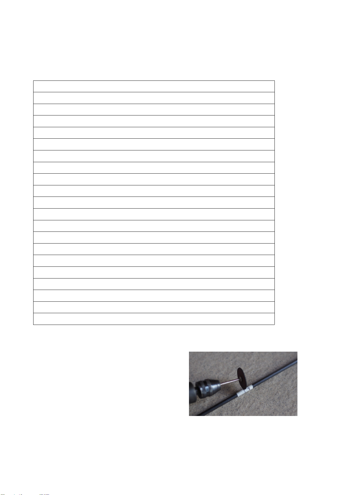
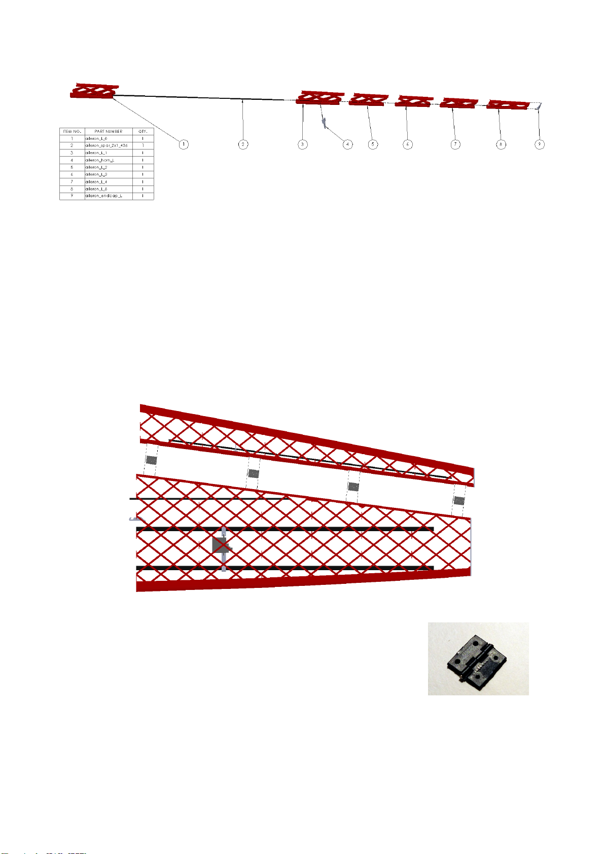
Choices based on hinge. You can use two kinds of hinges, both have same length and width
(roughly 28mm x 16 mm) but thickness is where they differ. European style is 1.2mm thick and Du-
Bro 117 is roughly 0.3 inch thick:
•parts in main directory have slots for European hinge
•parts under Options directory ending with suffix _dubro.STL have slots for Du-Bro 117
standard hinges
Choices based on wheel size:
•shoe_L.STL and shoe_R.STL will accommodate 45mm wheel
•shoe_L_50mm.STL and shoe_R_50mm.STL from Options directory will accommodate
50mm wheel
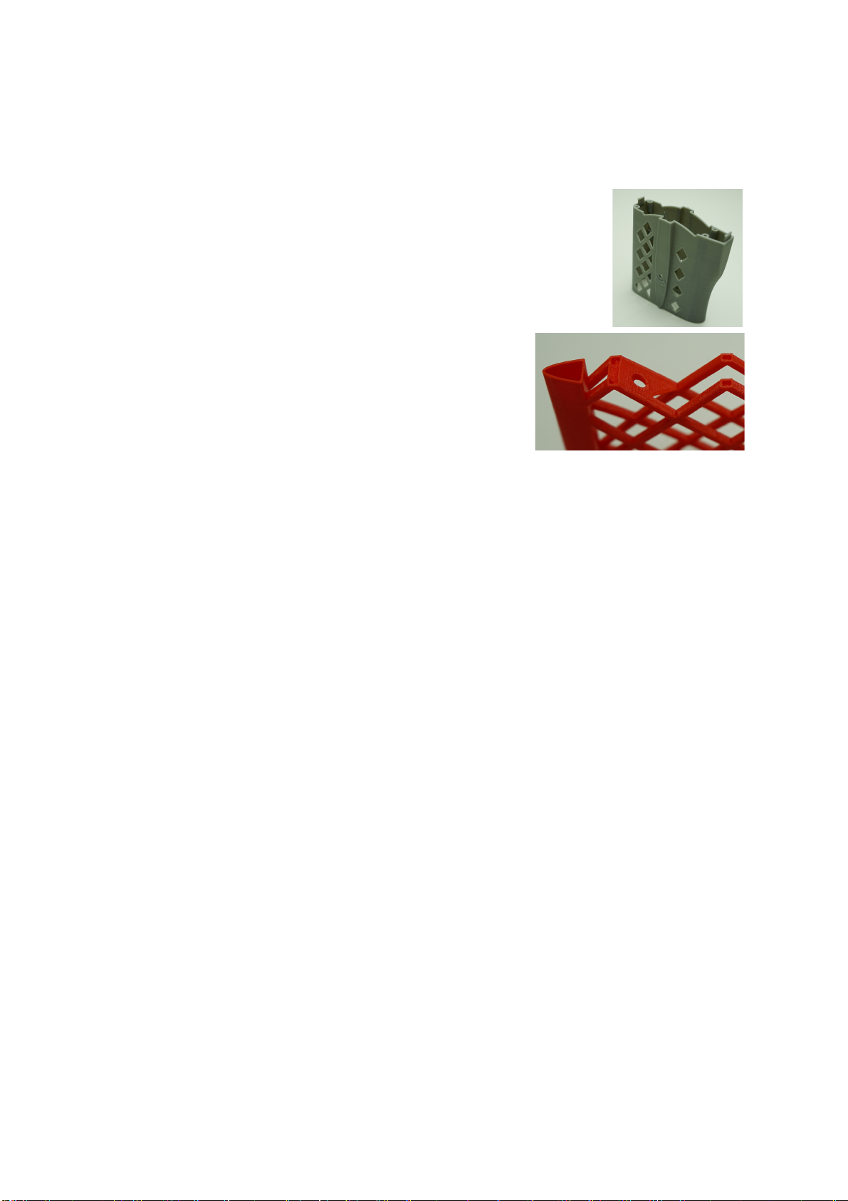
Choices for motor mount. In first version of Maripi files part fuse_0_SK3_35xx.STL had some
design issues that caused firewall breaking and complete motor separation from the fuselage after
rough landing or after longer use due to the motor vibrations. In version 1.1 this part was improved.
Namely carbon spars are protruding more into firewall and some small fillets were added. This fix
was still not good enough. That is why I improved it much more in this version. I added more fillets
on all critical places. Air inlets are much smaller and moved away from motor mount holes to
prevent cracks around motor screws. Also motor mount screw holes have now smaller countersink.
Despite all my changes some of you felt that it is still now enough and that is why added heavy duty
version of fuse_0 with thicker firewall and no countersinks for motor screws:
•fuse_0_SK3_35xx.STL in main directory is strong enough to withstand serious abuse
•fuse_0_SK3_35xx_heavy_duty.STL is even stronger but requires you to use your own
longer screws with flat bottom.
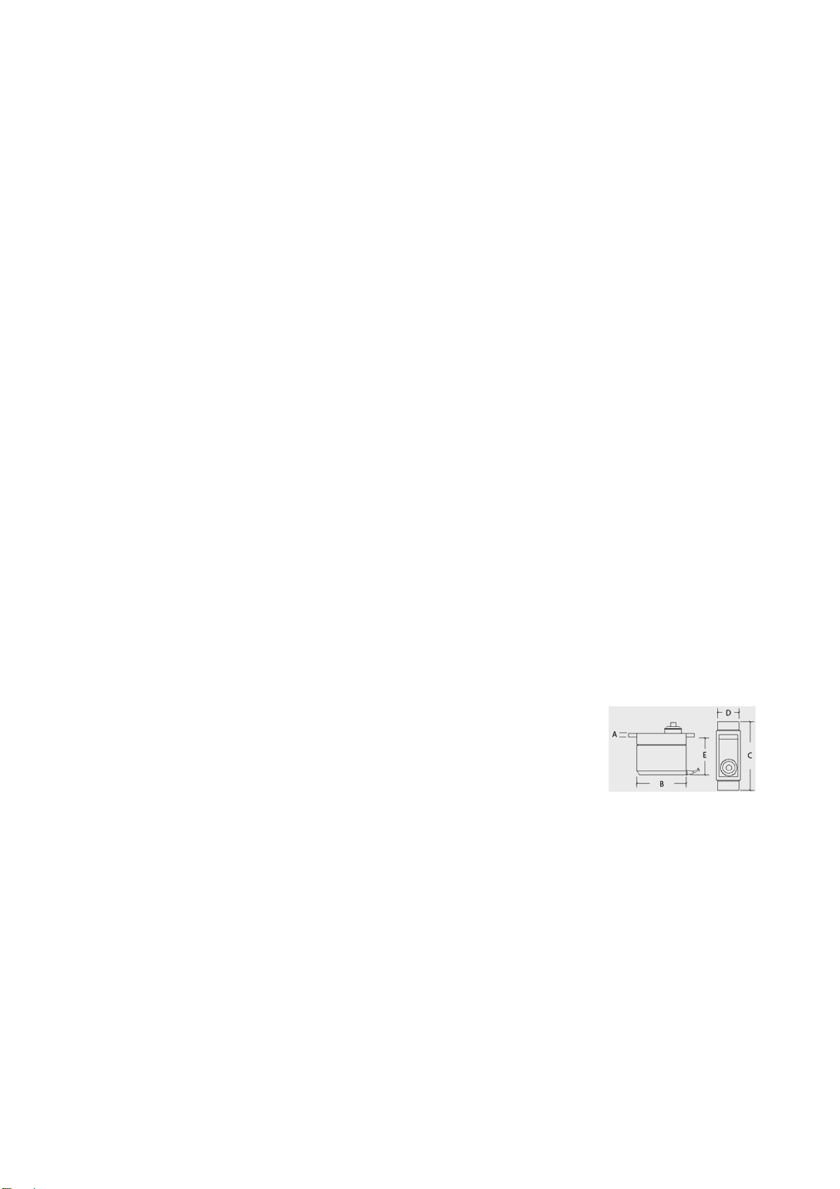
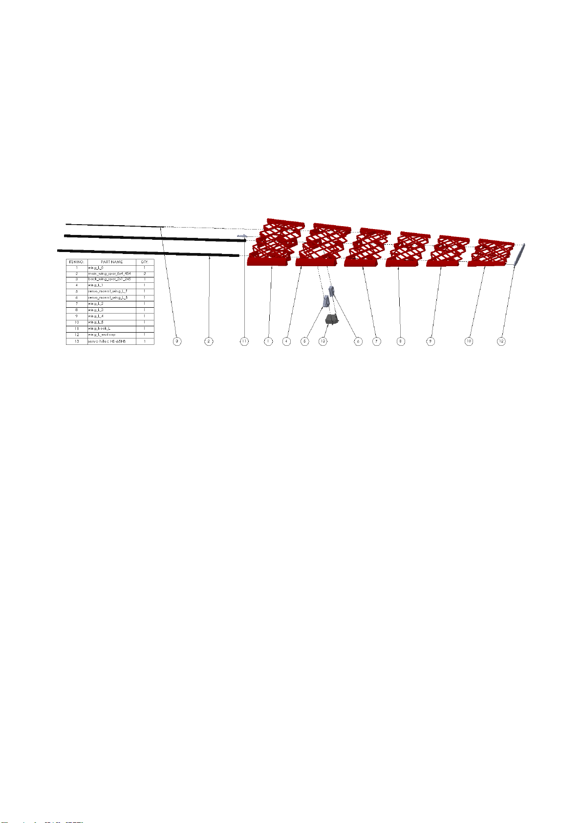
Choices based on servo in the wing:
•servo_mount_wing_[position]: will fit Hitec HS-65 (mg or hb) servo
A = 2 mm, B = 24 mm, C = 32.5 mm, D = 11.6 mm, E = 17 mm
•servo_mount_wing_generic_[position]: there are included both STL
and STEP file, you can customize it in software or manually after the
mount is printed out
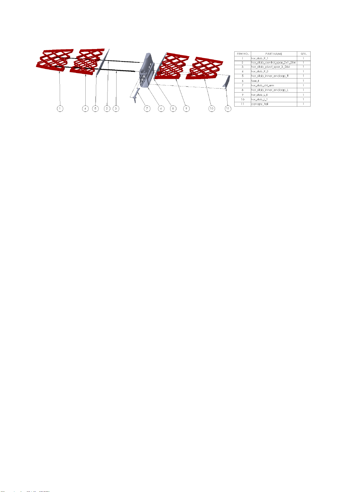
Choices based on servo in the fuselage:
•servo_plate_hs_65: will fit Hitec HS-65 (mg or hb) servo A = 2 mm, B = 24 mm, C = 32.5
mm, D = 11.6 mm, E = 17 mm
•servo_plate_generic: there are included both STL and STEP file, you can customize it in
software or manually after the plate is printed out
support@kragamodels.com
Preparation for assembly
KRAGA Maripi plane consists of parts that are printed and parts that you need to buy separately
(they are not included in the sold product) – carbon tubes, carbon rods, wheels, pinned hinges ...
List of required parts:
dimensions count
carbon tube ↕ 2x1 mm 1 m7
carbon tube ↕ 6x4 mm 1m2
carbon rod ↕ 3 mm 1 m1
carbon rod ↕ 4 mm 1 m1
covering film 2 m1
wheels 45 mm or 50 mm (⌀⌀max thickness 16 mm) 2
pinned hinge ↕ 16x28x1.2 mm or Du-Bro 11711
propeller 10 inch1
spinner 40 mm ⌀1
clevis thread M2 6
threaded coupler 2 mm thread M2⌀6
twine/cord 1.5 m1
⌀2x1 mm – means tube with outer diameter of 2mm and inner diameter of 1mm
⌀ 3 mm - means rod with diameter of 3mm
And of course you need electronics (motor, esc, 4 micro servos, battery).
support@kragamodels.com
Next step is to cut carbon tubes and rods into smaller pieces, which will be used as spars, joiners or
boom support of the plane. Don't forget to mark name on every piece to avoid confusion during the
assembly.
part dimensions count
main wing spar ↕ 6x4 mm 454 mm4
back wing spar ↕ 2x1 mm 245 mm 2
aileron spar ↕ 2x1 mm 436 mm2
horizontal stab. control spar ↕ 2x1 mm 284 mm1
horizontal stab. pivot spar ↕ 3 mm 284 mm1
vertical stab. main front spar ↕ 2x1 mm 97 mm1
vertical stab. main back spar ↕ 2x1 mm 80 mm1
vertical stab. mov spar ↕ 2x1 mm 165 mm1
fuse top spar ↕ 2x1 mm 858 mm2
fuse bottom spar ↕ 2x1 mm 862 mm2
fuse servo plate spar front ↕ 2x1 mm 68 mm1
fuse servo plate spar back ↕ 2x1 mm 51 mm1
wing joiner rod front ↕ 4 mm 300 mm1
wing joiner rod back ↕ 4 mm 280 mm1
landing leg spar front ↕ 3 mm 145 mm2
landing leg spar back ↕ 3 mm 161 mm2
wheel shaft ↕ 2x1 mm 23 mm2
tail leg spar ↕ 2x1 mm 80 mm1
aileron linkage carbon tube * ↕ 2x1 mm 44 mm1
horizontal stab. linkage carbon tube ↕ 2x1 mm 286 mm1
* needed only if you will be making custom carbon pushrods for aileron linkage
TIP: How to cut carbon spars. Wrap masking tape
around carbon spar and mark cut position. Use rotary
tool or X-ACTO fine saw to cut the spar. Work
outside or in room with good ventilation. Use
breathing mask to avoid inhaling carbon dust! After
cutting wipe out carbon dust from the spars using wet
tissue.
support@kragamodels.com
TIP: Joiner rods on the fuselage have diameter
of 4 mm, carbon spars in wings have inner
diameter of 4 mm. They should fit into each
other but sometimes the fit is too tight or you
cannot insert joiners rods into wing spars at all.
You can use drill and wet sandpaper to make
joiner rods thinner. Use breathing mask to avoid
inhaling carbon dust!
Remove support legs from all parts. Also sand all sharp edges
and printing imperfections to avoid covering foil damage.
support@kragamodels.com
Assembly
This assembly will describe always left side of the plane when it comes to symmetric parts. It is
recommended to use medium viscosity CA glue. You can use CA glue accelerator for faster curing
time. Dry fit all the parts before gluing them together.
Wing
Assembly left wing as sketched above.
You have an option here to use default servo mounts for Hitec HS-65 series servos (or other with
similar dimensions) or to customize included generic servo mounts. Don't forget to insert servo
mounts into wing_L_1 part when leading spars through.
Both main wing spars (main_wing_spar_6x4_454) should be aligned flush with base of wing_L_0
part. Back wing spar (back_wing_spar_2x1_245) should protrude 0.5 cm. It's purpose is to fix back
side of the wing on the fuselage and also to protect wing hook during transportation.
Do not forget to center your servos before gluing them in. Check also that your clevises fit servo
arm holes, drilling them when servo is in place could damage the wing. Lead servo cable through
the wing. The servo cable should come out of the wing near leading edge to meet servo cable hole
in the fuselage.
When all the parts are on their position, put glue on contact points where carbon spars are touching
printed parts.
support@kragamodels.com
Aileron
Assembly left aileron as sketched above. Carbon spar should be centered in the middle.
Don't forget to insert aileron_horn_L part into aileron_L_1 when leading spar through. When all the
parts are on their position, put glue on contact points where carbon spars are touching printed parts.
Wing
Some hinge slots are not deep enough to fit whole hinge length. Shorten all
hinges as shown on the picture. It has no benefit in terms of added stiffness
of rigidity to use whole hinge arm length as only small hinge area is in
contact with the wing.
Be careful when using glue near pinned part of the hinge. First insert the hinge into hinge hole and
then apply the glue from inner side of the wing. Do the same when gluing aileron to hinge. First
insert all hinges into hinge holes on aileron and then apply glue from inner side of aileron. Make
sure that aileron has enough space for moving from every side.
support@kragamodels.com
Horizontal stabilizer
Assembly the stabilizer as sketched above.
Carbon spars should be centered in the middle.
I recommend to install the clevis on the control arm before gluing it in. That saves you the hassle
later, installing it through service opening when the fuselage is assembled is more difficult.
When all the parts are on their position, put glue on contact points where carbon spars are touching
printed parts.
Canopy_tail has printing support which should be removed (triangle shape in the middle of the
canopy). Canopy_tail provides service access to the linkage mechanism and should NOT be glued
to the fuse_8 part.
support@kragamodels.com