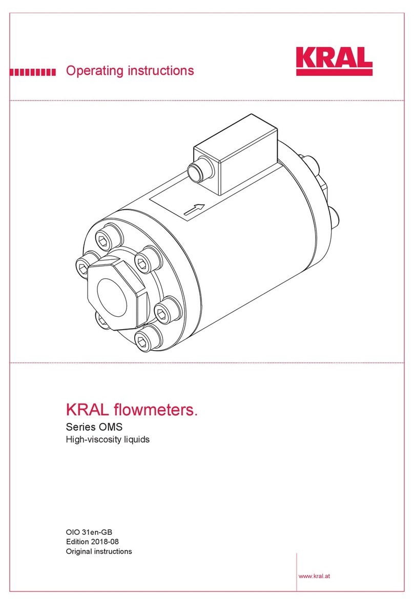
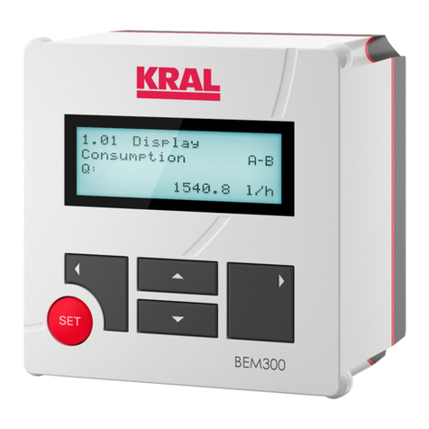
KRAL BEM 300 Series User manual

Operating Instructions
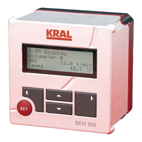
KRAL Electronics - BEM 300 Series.
OIE 15en
Edition 2019-12 HW 2.0/SW 2.0

2 OIE 15en Edition 2019-12 HW 2.0/SW 2.0 Operating Instructions
Table of Contents
KRAL Electronics – BEM 300 Series
About this document
□Target groups 4
□Symbols 4
□Danger levels 5
□Further applicable documents 5
□Safety instructions 5
Function description
□Volume measurement 6
□Mass calculation 6
□Averaging 6
□Flow direction detection 6
□Electronic evaluation 7
□Bus connection 7
□Applications of the KRAL electronic unit 8
▪Single-line measurement 8
▪Differential measurement 9
Transportation, storage and maintenance
□Unpacking and checking
the state of delivery 10
□Transportation 10
□Storage 10
□Disposal 10
▪Safety instruction for disposal 10
▪Disposing of the electronic unit 10
□Maintenance 10
□Cleaning 10
Installation and removal
□Safety instructions on installation,
removal and connection 11
□Installation 11
▪Dimensions 11
▪Scope of delivery 11
▪Installation in the control cabinet 12
▪Wall mounting 13
▪Pipe mounting / mounting on volumeter 13
□Removal 14
▪Removing the electronic unit
from the control cabinet 14
▪Removing the electronic unit
from the wall 14
▪Removing the electronic unit
from the pipe/volumeter 14
Electrical connection
□Terminal panel of the electronic unit 15
□Technical data of connections 16
▪Power supply 16
▪Tension spring terminals 16
▪Pulse inputs 16
▪Analog, pulse and relay outputs 16
▪Analog input display background
illumination 17
▪Display 17
▪Modbus interface 17
▪Ambient conditions 18
□Connection assignments 19
▪Pick ups 19
▪Analog outputs 19
▪Pulse outputs 19
▪Power supply 24 V DC 19
▪Serial interface 19
▪Analog input background illumination 20
□Connecting cables 20
▪Safety instructions for electrical
installation 20
▪Connecting cables to the tension
spring terminals 21
▪Connecting the sensors 22
▪Connecting analog and pulse outputs 22
▪Connecting the power supply 22
Commissioning
□Safety instructions for commissioning 23
□Checking the electronic unit 23
□Taking the electronic unit out of operation 23
Operation of the basic functions
□Key assignment 24
□Operation at a glance 25
▪General operating steps 25
▪Operating the basic functions 26
□Abbreviations, quantities and units 27
▪Abbreviations used 27
▪Quantities and units 27
▪Pulse signals 27
Menu description
□Menu structure 28
□Start 29
▪Start message 29
□Shortcut pages 29
▪1.07 Language selection 29
▪1.12 Help operation 29
▪Menu 7: Alarms 29
□Menu 1: Display 29
▪1.01 Volumeter A 29
▪1.02 Volumeter A Total with resetting 29
▪1.03 Reset collective error message 30
▪1.04 Information 30
▪1.05 Setting display brightness 30
▪1.06 Setting display contrast 30
▪1.07 Setting select language 30
Operating Instructions OIE 15en Edition 2019-12 HW 2.0/SW 2.0 3
Table of Contents
KRAL Electronics – BEM 300 Series
□Menu 2: Settings 30
▪2.01 Enable password 30
▪2.02 Select unit rate 31
▪2.03 Select unit total 31
▪2.04 Select unit density 31
▪2.05 Function analog output 31
▪2.06 Scale analog output 1 31
▪2.07 Averaging analog output 31
▪2.08 Scale pulse output 1 32
▪2.09 Start message 32
▪2.10 Address modbus 32
▪2.11 Function sensor 32
▪2.12 Averaging display rate 32
▪2.13 Function pulse input 33
▪2.14 Reset to factory setting 33
▪2.15 Decimal places 33
□Menu 3: K-factors Volumeter A 33
▪3.01 K-factor Volumeter A Point 1 33
□Menu 4: Density table 1 33
▪4.01 Density table 1 Point 1 33
□Menu 7: Alarms 33
Troubleshooting
□Information about faults 34
□Alarms 34
□Further faults 35
Accessories
□Accessories mounting 37
▪Universal mount fixing kit 37
▪Fixing kit for pipe mounting /
mounting on OMG 37
▪Fixing kit OME 38
▪Adapter set for conversion
of BEM 4U to BEM 300/500 38
□Accessories electrical connection 39
▪Rack mounting power
supply unit EEN 12 39
▪Plug-in power supply unit EEN 13 40
□Data acquisition accessories 41
▪Data logger BEA 60 and BEA 61 41
□Display accessories 42
▪Remote display BEA 59 42
Appendix
□Glossary 43
□Notes 45

4 OIE 15en Edition 2019-12 HW 2.0/SW 2.0 Operating Instructions
Target groups
About this document
About this doc ument The operating instructions form part of the BEM 500 electronic unit and must be kept for future
reference. Furthermore please observe the associated applicable documents.
Target groups
Symbols
Target group Tasks
Operator-owner □Keep these instructions available at the installation site for future
reference.
□Ensure that employees read and observe these instructions and the
associated documents, in particular the safety instructions and
warnings.
□Observe additional system-specific directives and regulations.
Specialist personnel, fitters □Read, observe and follow these instructions and the associated
documents, in particular the safety instructions and warnings.
Symbol Meaning
Warning personal injury
Note
Procedures installation and removal
Procedures electrical installation
Check or fault table
Operating steps for electronic unit
Faults in the electronic unit
Faults in the KRAL Volumeter
Faults in the system
Input errors
Request for action

Operating Instructions OIE 15en Edition 2019-12 HW 2.0/SW 2.0 5
Danger levels
About this document
Danger levels
Further applicable documents
Safety instructions
Warning Danger level Consequences of non-observances
Danger Immediate threat of danger Serious personal injury, death
Warning Possible threat of danger Serious personal injury, invalidity
Caution Potentially dangerous situation Slight personal injury
Caution Potentially dangerous situation Material damage
Declaration of conformity as per EU Directive 2014/30/EU
Corresponding operating instructions for the Volumeter
Corresponding operating instructions for the sensor
Calibration certificate
Worksheet
The following general safety instructions must be observed:
□No liability is accepted for damage arising through non-observance of the operating instructions.
▪Read the operating instructions carefully and observe them.
▪The operator-owner is responsible for the observance of the operating instructions.
▪Installation, removal and installation work may only be carried out by specialist personnel.
□Implement all the supply lines without faults.
□Observe the general regulations for the prevention of accidents as well as the local safety and
operating instructions.
□Observe the valid national and international standards and specifications of the installation
location.

6 OIE 15en Edition 2019-12 HW 2.0/SW 2.0 Operating Instructions
Volume measurement
Function description
Function descript ion With its functional scope the KRAL electronic unit covers a wide range of functions. The electronic unit is
optimized for use together with KRAL Volumeters. KRAL Volumeters generate a specific number of
pulses per flow volume unit - depending on the size and working point. This device-specific characteri-
stic is called the K-factor (unit: Pulses/Liter) and is listed in the enclosed calibration report.
The pulse signals of one volumeter can be evaluated. The following signals are available:
□PNP
□Namur
□NPN
For push-pull pick ups either PNP or NPN can be selected.
In addition the devices can also be equipped with further pick ups for flow direction detection. The elec-
tronic unit is supplied with settings in accordance with the customer requirements.
Together with diverse options for signal transfer with analog, pulse and bus outputs this means that an
extensive scope of performance is available that offers the following main possibilities:
Volume measurement
The instantaneous value of the volume flow (volume per time unit) is calculated from the measured
value of the incoming pulses per time unit and the stored mean K-factor and is displayed. Furthermore
the total number of measured pulses can be used to display the total flow (volume) as a total value since
the device was last reset. Rate values represent the current instantaneous values, total values corres-
pond to the sums since the last resetting.
Mass calculation
The instantaneous value of the mass flow (mass per time unit) is calculated from the measured value of
the incoming pulses per time unit and the stored values of mean K-factor and mean density and is dis-
played. Furthermore the total number of measured pulses can be used to display the total flow (mass)
as a total value since the device was last reset.
Rate values represent the current instantaneous values, total values correspond to the sums since the
last resetting.
Averaging
A strongly fluctuating flow rate causes a jumping display or as a result a fluctuating analog output. The
averaging function reduces this effect by generating a mean value across several measured values. The
number of measured values for averaging can be set, see "2.07 Averaging analog output", page 31, and
see "2.12 Averaging display rate", page 32.
Flow direction detection
In extreme cases the flow direction can change through pulsations, meaning through liquid waves in the
piping system. By using two pick ups which generate square wave signals out of phase by 90° (square
wave encoder signals) a reversal in the flow direction is recognized and taken into account when calcu-
lating the total value.
The electronic unit offers incremental encoding inputs for each volumeter. This means that the flow
direction can be determined without additional components and taken into account in the calculation at
any time.

Operating Instructions OIE 15en Edition 2019-12 HW 2.0/SW 2.0 7
Electronic evaluation
Function description
Electronic evaluation
The electronic unit receives signals from the pick ups and calculates the measured values which are
indicated in the display unit and which can be called up at the analog output or at the bus interface.
Possibilities of the electronic unit:
□Language selection
□Display of the measured values in different units (volumes, masses and temperatures)
□Averaged display values
□A density for conversion to mass
□Information message at faults or invalid inputs
□1 scaleable and assignable analog output 0 - 10V / 4 - 20 mA
□1 scaleable and assignable pulse output
Bus connection
The electronic unit can be connected to the system by means of a Modbus interface and can thus be
integrated optimally into existing systems. This ensures that simple, reliable and rapid data exchange
can be implemented.

8 OIE 15en Edition 2019-12 HW 2.0/SW 2.0 Operating Instructions
Applications of the KRAL electronic unit
Function description
Applications of the KRAL electronic unit
Different extension stages of the electronic unit are presented on the basis of the following examples.
This allows the required functional scope to be selected in accordance with the requirements.
Single-line measurement
Tab. 1 Extension stages single-line measurement
Extension stage Components Functions
Fig. 1 Basic
□1 Volumeter
□1 Pick up
□1 BEM 300 electronic unit
□Electronic evaluation
□Volume measurement
□1 Analog output
□1 Pulse output
Fig. 2 Basic +
Temperature
compensation
□1 Volumeter
□1 Pick up
□1 Temperature sensor
□1 BEM 500 electronic unit
□Electronic evaluation
□Volume measurement
□Temperature compensation
□Mass flow measurement
□Temperature compensation
□2 Relay outputs
□2 Analog outputs
□2 Pulse outputs
□Batching
Fig. 3 Basic +
Flow direction detection
□1 Volumeter
□2 Pick ups
□1 BEM 300 electronic unit
□Electronic evaluation
□Volume measurement
□Flow direction detection
□1 Analog outputs
□1 Pulse output
Fig. 4 Basic +
Flow direction detection +
Temperature
compensation
□1 Volumeter
□2 Pick ups
□1 Temperature sensor
□1 BEM 500 electronic unit
□Electronic evaluation
□Volume measurement
□Flow direction detection
□Mass flow measurement
□Temperature compensation
□2 Relay outputs
□2 Analog outputs
□2 Pulse outputs
□Batching

Operating Instructions OIE 15en Edition 2019-12 HW 2.0/SW 2.0 9
Applications of the KRAL electronic unit
Function description
Differential measurement
Tab. 2 Extension stages differential measurement
Extension stage Components Functions
Fig. 5 Basic
□2 Volumeters
□1 Pick up each
□1 BEM 500 electronic unit
□Electronic evaluation
□Differential measurement
□2 Relay outputs
□2 Analog outputs
□2 Pulse outputs
Fig. 6 Basic +
Temperature
compensation
□2 Volumeters
□1 Pick up each
□1 Temperature sensor each
□1 BEM 500 electronic unit
□Electronic evaluation
□Differential measurement
□Mass flow measurement
□Temperature compensation
□2 Relay outputs
□2 Analog outputs
□2 Pulse outputs
Fig. 7 Basic +
Flow direction detection
□2 Volumeters
□2 Pick ups each
□1 BEM 500 electronic unit
□Electronic evaluation
□Differential measurement
□Flow direction detection
□2 Relay outputs
□2 Analog outputs
□2 Pulse outputs
Fig. 8 Basic +
Flow direction detection +
Temperature
compensation
□2 Volumeters
□2 Pick ups each
□1 Temperature sensor each
□1 BEM 500 electronic unit
□Electronic evaluation
□Differential measurement
□Flow direction detection
□Mass flow measurement
□Temperature compensation
□2 Relay outputs
□2 Analog outputs
□2 Pulse outputs

10 OIE 15en Edition 2019-12 HW 2.0/SW 2.0 Operating Instructions
Unpacking and checking the state of delivery
Transportation, storage and maintenance
Transportation , storage and ma in tenance Unpacking and checking the state of delivery
1. On delivery unpack the electronic unit and check for damage during transportation.
2. Report damage during transportation immediately to the manufacturer.
3. Dispose of packing material in accordance with the locally applicable regulations.
Transportation
► If possible, transport the electronic unit in the original packaging, while observing the ambient condi-
tions, see "Ambient conditions", page 18.
Storage
► If possible, store the electronic unit in original packaging in a cool and dry place, while observing the
ambient conditions, see "Ambient conditions", page 18.
Disposal
Safety instruction for disposal
Disposing of the electronic unit
► As electronic waste the electronic unit has to be disposed of properly.
Maintenance
The electronic unit is maintenance-free.
Cleaning
In order to clean the electronic unit wipe the housing with a soft cloth. In case of stronger soiling moisten
the cloth with water that has a common detergent added. Only wipe the surface off lightly with a moist
cloth. Under no circumstances may water penetrate the inside of the electronic unit!
The following safety instruction must be observed during disposal:
► Observe the local regulations on disposal.

Operating Instructions OIE 15en Edition 2019-12 HW 2.0/SW 2.0 11
Safety instructions on installation, removal and connection
Installation and removal
Installation and removal Safety instructions on installation, removal and connection
Installation
Dimensions
Scope of delivery
The following components belong to the scope of delivery of the electronic unit:
□Operating Instructions
□Password
□Worksheet
□Mounting frame including screws and lock washers
□Terminal tool
□KRAL tool set
The following safety instructions must be observed:
□All installation and removal work may only be carried out by qualified personnel.
▪Read the operating instructions and observe the relevant instructions.
□The electronic unit is a precision instrument.
▪Ensure cleanliness and take care during installation and removal.
▪Do not take apart the electronic unit.
□The following qualifications are required for the electrical connection:
▪Practical electrotechnical training
▪Knowledge of the safety guidelines at the workplace
▪Knowledge of the electrotechnical safety guidelines
Fig. 1 Dimensions of BEM 300 electronic unit
1Height:
2Width:
3Depth:
116 mm
116 mm
116 mm
1
2
3

12 OIE 15en Edition 2019-12 HW 2.0/SW 2.0 Operating Instructions
Installation
Installation and removal
Installation in the control cabinet
The electronic unit can be mounted in control cabinets having a sheet thickness of 0.5 – 5 mm by using
the supplied mounting frame. The mounting frame consists of a front frame 2 and a sealing frame 4, see
Fig. 2, page 12.
When the space is limited, mounting is also possible without a housing cover 6 and gasket with cable
entries 5, see Fig. 2, page 12.
Required minimum mounting depth: 80 mm
Dimensions of front frame:
□Height: 145 mm
□Width: 145 mm
□Depth: 12 mm
Aids:
□KRAL tool set
1Electronic unit
2Front frame
3Control cabinet
4Sealing frame
5Seal with cable
entries
6Housing cover
Fig. 2 Control cabinet mounting BEM 500
a117 mm
b117 mm
Fig. 3 Control cabinet section
1
2
3
4
5
6
a
b

Operating Instructions OIE 15en Edition 2019-12 HW 2.0/SW 2.0 13
Installation
Installation and removal
1. Create a control cabinet section, see Fig. 3, page 12.
2. When the space is limited, remove the housing cover 6 and gasket with cable entries 5.
3. Slide the front frame 2 from behind onto the electronic unit 1.
4. Place the electronic unit with the front frame from the front into the control cabinet section, see
Fig. 3, page 12.
5. Slide the sealing frame 4 from behind onto the electronic unit, whereby the sealing surface has to
point to the front.
6. Fasten the front frame and sealing frame using the 4 supplied screws and lock washers. Tighten the
screws carefully.
Tightening torque: 1 Nm
The electronic unit is ready for the connection of the cables.
Wall mounting
A universal mount, that is available as an accessory, is used for wall mounting see "Accessories moun-
ting", page 37.
Prerequisite:
□Universal mount is mounted to the wall
□All cables have been cut to length and connected
Aids
□KRAL tool set
1. Slide the electronic unit 1 into the universal mount 2.
2. Fasten the electronic unit using the supplied screws, washers and wedge lock washers.
The electronic unit is ready to operate after the power supply has been switched on.
Pipe mounting / mounting on volumeter
The electronic unit can be mounted to the pipe or on the volumeter by means of the universal mount and
the corresponding mounting set. The required mounting set is available as an accessory, see "Accesso-
ries mounting", page 37.
DANGER
Risk of death resulting from electric shock.
► Ensure that the power supply is disconnected.
► The electronic unit may only be connected by an authorized electrician.
1Electronic unit
2Universal mount
Fig. 4 Universal mount for wall mounting
1
2

14 OIE 15en Edition 2019-12 HW 2.0/SW 2.0 Operating Instructions
Removal
Installation and removal
Prerequisite:
□All cables have been cut to length and connected
Aids
□KRAL tool set
1. Mount the universal mount 2 on the mounting set 3.
2. Mount the mounting set including universal mount to the pipe/volumeter.
3. Slide the electronic unit into the universal mount.
4. Fasten the electronic unit using the supplied screws, washers and wedge lock washers.
The electronic unit is ready to operate after the power supply has been switched on.
Removal
Prerequisite:
□Power supply switched off
Aids:
□KRAL tool set
□Terminal tool
Removing the electronic unit from the control cabinet
1. Disconnect all the wires
2. Unscrew the connecting screws between the front and sealing frames.
3. Pull off the sealing frame to the rear.
4. Pull the electronic unit with front frame from the front out of the control cabinet.
5. Press the front frame to the rear and pull it off the electronic unit.
Removing the electronic unit from the wall
1. Unscrew the connecting screws between the electronic unit and the universal mount.
2. Slide the electronic unit out of the universal mount.
Removing the electronic unit from the pipe/volumeter
1. Unscrew the connecting screws between the electronic unit and the universal mount.
2. Slide the electronic unit out of the universal mount.
Fig. 5 Fixing kit for pipe mounting /
KRAL Volumeter OMG series
Fig. 6 Fixing kit for KRAL Volumeter OME
series
1Electronic unit
2Universal mount
3Fixing kit for pipe mounting/OMG
1Electronic unit
2Universal mount
3Fixing kit OME
1
2
3
1
2
3

Operating Instructions OIE 15en Edition 2019-12 HW 2.0/SW 2.0 15
Terminal panel of the electronic unit
Electrical connection
Electrical connection Terminal panel of the electronic unit
The bus is connected via terminals. The assignment of the terminals is shown in the terminal diagram.
The bus interface address can be selected per software, see "2.10 Address modbus", page 32.
Fig. 1 Terminal panel of the BEM 300 electronic unit
1 Power supply 24 V DC
2 Analog output 4 ... 20 mA
3 Analog output 0 ... 10 V
4 Serial interface RS232
5 Bus interface RS485
6 Pick up 1
7 Pick up 2
8 Analog input 0 ... 10 V
Background illumination
9 Pulse output
1
2
3
4
5
6
7
8
9
000766
1
2
3
4567
89
10
11
12 13 14 15 16 17 18 19 20 21
A+A+
B-B-

16 OIE 15en Edition 2019-12 HW 2.0/SW 2.0 Operating Instructions
Technical data of connections
Electrical connection
Technical data of connections
Power supply
Tension spring terminals
Pulse inputs
Analog, pulse and relay outputs
Designation Data
Power supply □range 24 V DC ± 20%
Power consumption max. □0,5 A
Insulation voltage □< 500 V
Cable type Terminating range
Strand □0.08 – 2.5 mm2
Litz wires □0.08 – 2.5 mm2
Wire end ferrule □0.08 – 1.5 mm2
Component Data
Pulse inputs □minimum limit frequency 0,5 Hz
□maximum limit frequency 20 kHz
□powers supply 24 V DC or Namur 8.2 V
Component Data
Analog output 4 - 20 mA □active voltage sources
□short-circuit proof
□load < 500 Ω
□electrical isolation: 500 Veff
□resolution: 1 μA
□scalable
□temperaturdrift: ±0,1 %
□calibration tolerance: ±0,1 %
□reaction time: 20 ms x smoothing value
Analog output 0 - 10 V □active voltage sources
□short-circuit proof
□load > 500 Ω
□resolution: 1 mV
□scalable
□temperaturdrift: ±0,1 %
□calibration tolerance: : ±0,1 %
□cycle time: 20 ms

Operating Instructions OIE 15en Edition 2019-12 HW 2.0/SW 2.0 17
Technical data of connections
Electrical connection
Analog input display background illumination
Display
Modbus interface
Pulse output □active pulse sources (PNP transistor switches power
supply)
□maximum output current: 20 mA
□short-circuit proof
□load > 1 kΩ
□scalable
□signal level at 24 V DC power supply:
▪high > 20 V DC
▪low < 1 V DC
□flow direction detection possible in "Encoder" mode
□pulse width (high) settable from 2–200 ms
□max. output frequency at pulse width 2 ms: 250 Hz
Component Data
Analog input 0 - 10 V □input impedance: 3,4 kΩ
□adjustable via menu only for U = 0 V
Designation Data
Text display □4 lines / 20 characters
Updating rate □100 ms
Background illumination □20 levels, can be adjusted via software or analog input
Contrast □20 levels, can be adjusted via software
Language selection □german
□english
□french
□spanish
Designation Data
Interface type □RS 232 (SLAVE)
□RS 485 (SLAVE)
Baud rate □9600 bauds
Data format □8N1 (8 data bit, no parity, 1 stop bit)
Protocol □Modbus RTU
Processor cycle time □20 ms
Component Data

18 OIE 15en Edition 2019-12 HW 2.0/SW 2.0 Operating Instructions
Technical data of connections
Electrical connection
The following variables are available at the Modbus:
Tab. 1 Variables at the Modbus
Example for Total TA1:
Send command: 010341000002D037
Result: 0103040001609E025B
The double word begins with the fourth byte (=00) and ends with the seventh byte (=9E).
Calculation of the value: 1*2^16+6*2^12+9*2^4+14*2^0=90270
Note: A change in the decimal places in the electronic unit must be taken into consideration when
evaluating data via the Modbus! The variable values are transferred without decimal point. The
conversion has to be taken into consideration during further processing.
The Modbus address is set in Menu 2.22, see "2.10 Address modbus", page 32.
Note: Data exchange via the bus connection is not password-protected! Write access deletes existing
values. Therefore we only recommend reading of the data.
Ambient conditions
Variable
designation
HEX
address
Length Designation Quan-
tity
Command
Serial number 0x4012 DW DOUBLE WORD 32 bit –
Software 0x4020 WWORD 16 bit –
Hardware 0x410A WWORD 16 bit –
Display Volumeter A QA 0x4006 DW DOUBLE WORD 32 bit 01034006000231CA
Display Volumeter A Total TA1 0x4100 DW DOUBLE WORD 32 bit 010341000002D037
Display Volumeter A Total TA2 0x4102 DW DOUBLE WORD 32 bit 01034102000271F7
Criterion Data
Storage temperature □Range -20° – +80 °C
Operating temperature □Range -20° – +70 °C
Humidity □97% relative humidity, non-condensing
EMC emitted interference and immu-
nity to interference
□EN 61326
Vibration □EN 60068–2–47
□EN 60068–2–64
Shock □EN 61373
Isolation □> 500 V
Degree of protection □IP 65

Operating Instructions OIE 15en Edition 2019-12 HW 2.0/SW 2.0 19
Connection assignments
Electrical connection
Connection assignments
Pick ups
Analog outputs
The data logger can be connected to the analog outputs 4–20 mA, see "Data acquisition accessories",
page 41.
Pulse outputs
The data logger can be connected to these connections, see "Data acquisition accessories", page 41.
Power supply 24 V DC
Different power supply units are available as accessories, see "Accessories electrical connection",
page 39. These are connected here.
Serial interface
Connection Function Terminal
Pick up 1 U+24 V DC 12
Signal 13
Gnd 14
Pick up 2
(+ 90°)
U+24 V DC 15
Signal 16
Gnd 17
Connection Function Terminal
Analog output 1 4–20 mA Signal 3
Gnd 4
Analog output 1 0–10 V Signal 5
Gnd 6
Connection Function Terminal
Pulse output 1 Signal 20
Gnd 21
Connection Terminal
+24 V DC 1
Gnd 2
Interface Function Terminal
RS 485 A10
B11
RS 232 TxD 7
RxD 8
Gnd 9

20 OIE 15en Edition 2019-12 HW 2.0/SW 2.0 Operating Instructions
Connecting cables
Electrical connection
Analog input background illumination
Connecting cables
Safety instructions for electrical installation
Connection Function Terminal
LCD Control In 0–10 V 18
Gnd 19
The following safety instructions must be observed during the electrical installation:
□The following qualifications are required for the electrical connection:
▪Practical electrotechnical training
▪Knowledge of the safety guidelines at the workplace
▪Knowledge of the electrotechnical safety guidelines
□The connecting lines of the sensor connections are to be shielded and laid separately from
the supply and measuring lines.
□Ensure that the power supply is correct (24 V DC).
Table of contents
Other KRAL Measuring Instrument manuals

KRAL
KRAL OMH Series User manual

KRAL
KRAL BEM 100 User manual

KRAL
KRAL OME Series User manual

KRAL
KRAL BEM 300 User manual

KRAL
KRAL Volumeter OMG 13 User manual

KRAL
KRAL OMS Series User manual

KRAL
KRAL Volumeter OMG Series User manual

KRAL
KRAL OMP Series User manual

KRAL
KRAL BEM 200 User manual

KRAL
KRAL OMG Series User manual
Popular Measuring Instrument manuals by other brands

Extech Instruments
Extech Instruments EX810 user manual

Rosemount
Rosemount 6888Xi Reference manual

D-Link
D-Link mydlink DSP-W215 user manual

LB Altimeters
LB Altimeters ARES II manual

ProMinent
ProMinent DULCOMETER Installation and configuration manual

Ashcroft
Ashcroft DG25 Installation and operating instructions