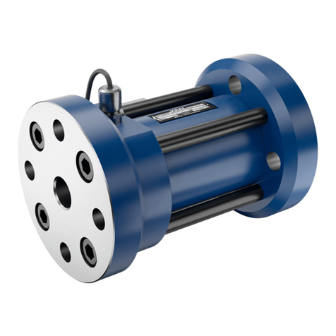
KRAL OME Compact Series User manual

Operating instructions
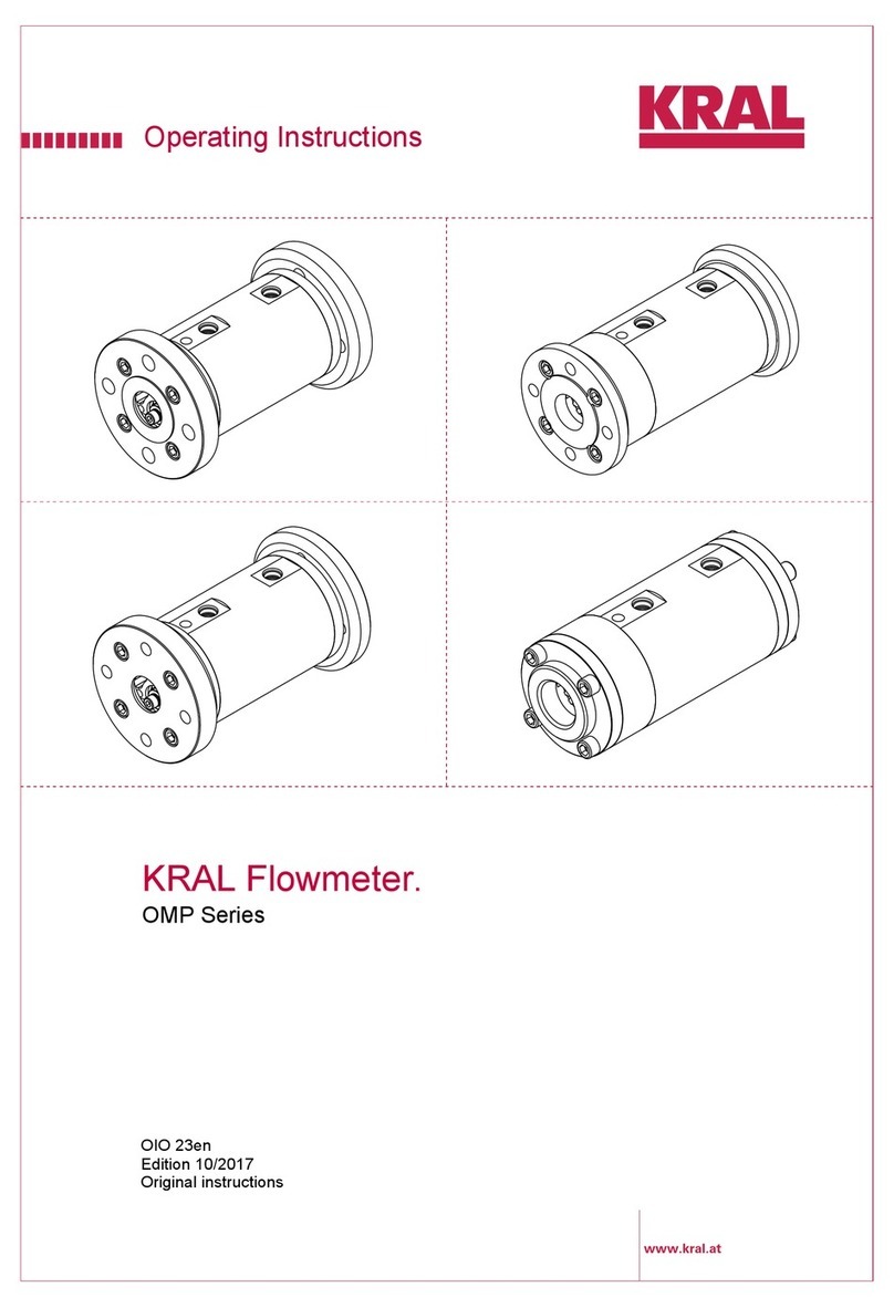
KRAL flowmeters.
OME Compact series
OIO 20en-GB
Edition 2022-01
Original instructions
www.kral.at

Table of contents
1 About this document ..................................................... 4
1.1 General information .......................................................4
1.2 Target groups ................................................................4
1.3 Symbols.........................................................................4
1.3.1 Danger levels ....................................................4
1.3.2 Danger signs.....................................................4
1.3.3 Symbols in this document .................................5
1.4 Associated documents ..................................................5
2 Safety .............................................................................. 5
2.1 Proper use .....................................................................5
2.2 Foreseeable misuse ......................................................5
2.3 Obligations of the operator-owner .................................6
2.4 Safety instructions .........................................................6
2.4.1 Fundamental safety instructions .......................6
3 Identification................................................................... 7
3.1 Type code......................................................................7
3.2 Rating plate ...................................................................7
4 Technical data ................................................................ 8
4.1 Operating limits..............................................................8
4.2 Pressure pulsation.........................................................8
4.3 Maximum values............................................................8
4.4 Substitute operating data...............................................9
4.5 Sound pressure level.....................................................9
4.6 Dimensions and weights................................................9
4.6.1 OME with compact sensor (BSPP thread)........9
4.6.2 OME with Smart Solution electronic unit
(BSPP thread).................................................10
4.6.3 OME with compact sensor (DIN flange)..........10
4.6.4 OME with Smart Solution electronic unit
(DIN flange).....................................................11
4.7 Compact sensor specification......................................12
4.8 Smart Solution electronic unit specification .................12
5 Function description.................................................... 13
5.1 Structure ......................................................................13
5.2 Functional principle......................................................13
5.3 Rolling bearings...........................................................13
5.4 Signal generation.........................................................13
5.5 Linearization ................................................................14
5.6 Compact sensor ..........................................................14
5.7 Smart Solution electronic unit......................................14
6 Transportation, storage............................................... 14
6.1 Dangers during transportation .....................................14
6.2 Dangers during storage ...............................................14
6.3 Unpacking and checking the state of delivery .............14
6.4 Transporting flowmeters ..............................................15
6.5 Storing the flowmeter...................................................15
7 Preservation ................................................................. 16
7.1 Preservation table........................................................16
7.2 Preserving the inner surfaces......................................16
7.3 Preserving the outer surfaces......................................16
7.4 Removing the preservation..........................................16
8 Installation, removal .................................................... 17
8.1 Dangers during installation ..........................................17
8.2 Dangers during removal ..............................................17
8.3 Installing the flowmeter ................................................17
8.3.1 Protecting the flowmeter against soiling ..........17
8.3.2 Installation types..............................................18
8.3.3 Installation recommendation............................19
8.3.4 Installing the flowmeter....................................20
8.4 Removing the flowmeter ..............................................20
9 Connection.....................................................................21
9.1 Dangers during connection work .................................21
9.2 Connecting the flowmeter to the pipe system ..............21
9.3 Connecting the flow meter electrically .........................22
10 Operation........................................................................22
10.1 Dangers during operation ............................................22
10.2 Commissioning ............................................................22
10.2.1 Cleaning the pipe system ................................22
10.2.2 Checking the function ......................................23
10.2.3 Commissioning the flowmeter .........................23
10.3 Decommissioning.........................................................24
10.3.1 Switching off the flowmeter..............................24
10.4 Recommissioning.........................................................24
10.4.1 Recommissioning the flowmeter......................24
11 Maintenance...................................................................24
11.1 Required maintenance.................................................24
11.2 Maintaining flowmeters ................................................25
11.3 Recalibration of the flowmeter .....................................25
12 Servicing ........................................................................25
12.1 Dangers during servicing .............................................25
12.2 Flowmeter ....................................................................26
12.2.1 Removing seals and ball bearings...................26
12.2.2 Installing seals and ball bearings.....................27
12.3 Compact sensor...........................................................28
12.3.1 Removing the sensor insert.............................28
12.3.2 Installing the sensor insert...............................28
12.3.3 Check the function of the compact sensor ......29
12.4 Smart Solution electronic unit ......................................30
12.4.1 Removing the Smart Solution electronics unit
.........................................................................30
12.4.2 Installing the Smart Solution electronics unit...31
12.4.3 Testing the Smart Solution electronics unit .....31
13 Disposal..........................................................................32
13.1 Dangers during disposal ..............................................32
13.2 Dismantling and disposing of the flowmeter ................32
14 Troubleshooting ............................................................32
14.1 Possible faults..............................................................32
14.2 Troubleshooting ...........................................................33
15 Spare parts.....................................................................35
15.1 Maintenance kit OME 13 - 52 ......................................35
15.2 Sensor insert for compact sensor ................................35
15.3 Smart Solution electronic unit ......................................36
16 Accessories ...................................................................36
16.1 Trace heating ...............................................................36
17 Appendix ........................................................................37
17.1 Tightening torques for screws with metric screw
threads with and without wedge lock washers.............37
2OIO 20en-GB Edition 2022-01 Operating instructions
1 About this document
1.1 General information
1 About this document
1.1 General information
These instructions form part of the product and must be kept for future reference. Furthermore please
observe the associated documents.
1.2 Target groups
The instructions are intended for the following persons:
oPersons who work with the product
oOperator-owners who are responsible for the use of the product
Persons who work with the product must be qualified. The qualification ensures that possible dangers
and material damage that are connected to the activity are detected and avoided. These persons are
qualified personnel who carry out the work properly due to their training, knowledge and experience
and on the basis of the relevant provisions.
Information on the required qualification of the personnel is provided separately at the beginning of the
individual chapters in these instructions. The following table provides an overview.
Target group Activity Qualification
Transport personnel Transporting,
unloading, setting up
Qualified personnel for transport, mobile crane operators,
crane operators, forklift operators
Fitter Mounting,
connection
Qualified personnel for mounting
Electrician Electrical connection Qualified personnel for electric installation
Trained personnel Delegated task Personnel trained by the operator-owner who know the
task delegated to them and the possible dangers arising
through improper behaviour.
Tab.1: Target groups
1.3 Symbols
1.3.1 Danger levels
Signal word Danger level Consequences of non-observance
DANGER Immediate threat of danger Serious personal injury, death
WARNING Possible threat of danger Serious personal injury, invalidity
CAUTION Potentially dangerous situation Slight personal injury
ATTENTION Potentially dangerous situation Material damage
1.3.2 Danger signs
Meaning Source and possible consequences of non-observance
Electrical voltage Electrical voltage causes serious physical injury or death.
Raised load Falling objects can result in serious physical injury or death.
kg
Heavy load Heavy loads can result in serious back problems.
4OIO 20en-GB Edition 2022-01 Operating instructions
2 Safety
1.4 Associated documents
Meaning Source and possible consequences of non-observance
Risk of slipping Discharging pumped liquid and oils on the foundation or tread surfaces
can cause falls with serious physical injury or death.
Flammable sub-
stances
Discharging pumped liquid and oils can be easily inflammable and can
result in serious burns.
Hot surface Hot surfaces can cause burns.
1.3.3 Symbols in this document
Meaning
Warning personal injury
Safety instruction
Request for action
1.
2.
3.
Multi-step instructions for actions
Action result
Cross-reference
1.4 Associated documents
oCalibration certificate
oDeclaration of Conformity according to EU Directive 2006/42/EC
oManufacturer's declaration according to EU Directive 2014/68/EU
oRelevant operating instructions for attachments (e.g. pick up, temperature sensor, electronics)
2 Safety
2.1 Proper use
oFlowmeter solely for flow measurement of lubricating liquids that are chemically neutral and that do
not contain gas or solid components.
oFlowmeters require operation with clean liquids. If coarse soiling, solid particles in the liquid or ab-
rasive fine particles occur during operation, the flowmeter must be protected additionally by a cor-
respondingly dimensioned operating filter in the pipe system.
oUse the flowmeter only within the operating limits specified on the rating plate and in the chapter
"Technical data". Deviating operating data can result in damage to the flowmeter. If the operating
data does not match the specifications on the rating plate, please contact the manufacturer.
oStrong changes in the flow rate (for example rapid shutdown, pulsations, etc.) cause marked pres-
sure differences in the flowmeter and can damage the measuring unit. The pressure loss of the
flowmeter must not exceed the values shown in the chapter "Technical data".
2.2 Foreseeable misuse
oAny use that extends beyond the proper use or any other use is misuse.
oThe product is not suitable for pumping liquids outside the operational limits.
oAny bypassing or deactivation of safety equipment during operation is prohibited.
Operating instructions OIO 20en-GB Edition 2022-01 5

2 Safety
2.3 Obligations of the operator-owner
The operator-owner is the person who operates the product commercially or permits a third party to
use it and who bears the legal responsibility for the product, the protection of the personnel and third
parties during its operation.
The product is used in industrial applications. The operator-owner is therefore subject to the statutory
obligations concerning occupational health and safety.
In addition to the safety instructions in these instructions, the regulations on safety, accident prevention
and environmental protection respectively valid for the range of application of the product are to be ob-
served.
2.4 Safety instructions
2.4.1 Fundamental safety instructions
The following safety instructions must be strictly observed:
oRead and observe these operating instructions carefully.
oRead the operating instructions for the electronic unit and the sensors carefully and observe them.
oWork must only be carried out by qualified/trained personnel.
oWear personal protective equipment and work carefully.
oPumped liquids can be subject to high pressure and can result in personal injury and damage to
property in case of incorrect operation or damaged components.
oPumped liquids can be hot, poisonous, combustible and caustic.
oObserve the associated data sheets and safety regulations when handling dangerous materials.
oAvoid skin contact with system parts carrying liquids at operating temperatures exceeding 60°C.
oCollect any discharging pumped liquid safely and dispose of it in an environmentally compatible
manner in accordance with the applicable local regulations. Neutralise residues.
oKeep the mounting surfaces, scaffolding, ladders, lifting platforms and tools clean in order to pre-
vent slipping or stumbling.
oIf pressurised or energised components are damaged, shut down the flow meter immediately. Re-
place the components or flow meter.
oHousing and flanges of the OME series KRAL flow meter are anodised. When installing the flow
meter in a pipeline, electrical interruptions to the earthed pipeline system cannot be ruled out. A
possible interruption of the earthing must therefore be taken into account by the operator.
6OIO 20en-GB Edition 2022-01 Operating instructions
3 Identification
3.1 Type code
3 Identification
3.1 Type code
OME-020.JDAAFD.0001
3
4
5
2
7
68
9
1
Fig.1: Type code
1Series
2Size
3Sensor equipment (pick up)
4Function of the sensor equipment
5Bearing material
6Seal material
7Mechanical connection
8Electrical connection
9Version index
Item Designation Description
1Series OME Economy
2Size Corresponds to the diameter of the measuring screw large in [mm]
3Sensor equipment
(pick up)
J BEG 60-62 (compact sensor)
X Special design
4Function of the
sensor equipment
D With flow direction recognition, with temperature compensation
X Special design
5Bearing material A Steel
X Special design
6Seal material A FPM (FKM)
B FFPM (FFKM)
C Low-temperature FPM
D EPDM
X Special design
7Mechanical
connection
A Thread connection BSPP
B Flange connection DIN
C Thread connection NPT
D Flange connection ANSI
X Special design
8Electrical
connection
C Cable gland compact sensor
D Fixing kit for display and processing unit
E Smart Solution version
X Special design
9Version index For internal administration
Tab.2: Type code
3.2 Rating plate
1 2 3
4567
Fig.2: Rating plate
1Serial number
2Construction year
3K-factor
4Preferred flow direction
5Max. temperature
6Series
7Max. pressure
Operating instructions OIO 20en-GB Edition 2022-01 7

4 Technical data
4.1 Operating limits
4 Technical data
4.1 Operating limits
The values specified on the rating plate and the calibration certificate apply. The permissible operating
limits of individual values influence each other so that every application is checked individually by the
manufacturer when selecting the flowmeter.
If no operating data are provided by the orderer, standardized substitute operating data are used.
4.2 Pressure pulsation
10 3020 40 t [ms]
30
10
20
0
p
[bar]
Fig.3: Pressure pulses
Strong pressure pulsations in the system can
reduce the service life of the flowmeter.
4.3 Maximum values
The following table shows the respective maximum values that, however, may not occur simultan-
eously. In addition, the operating limits of the corresponding completion, of the sealing material and of
the compact sensor or Smart Solution electronic unit must be observed.
Size
Parameter Unit 13 20 32 52
Flow rate
oQmax [l/min] 15 45 150 525
oQrated [l/min] 10 30 100 350
oQmin [l/min] 0.1 0.3 1.0 3.5
Max. pressure [bar] 40
Min.-max. temperature [°C] -20...+125
Min.-max. viscosity [mm2/s] 1–1000000
Measuring chamber volume [ml/U] 1.65 6.24 25.6 112.8
Speed
on (Qmax)[min-1] 9120 7260 5850 4658
on (Qrated)[min-1] 6060 4830 3900 3105
on (Qmin)[min-1] 61 48 39 31
Number of poles K1 2
K factor K1 [P/l] 1214 321 78 17.73
Millilitres/pulse K1 [ml/P] 0.824 3.12 12.8 56.4
Pulse frequency
of1 (Qmax)[Hz] 304 242 195 155
of1 (Qrated)[Hz] 202 161 130 104
of1 (Qmin)[Hz] 2.0 1.6 1.3 1.0
8OIO 20en-GB Edition 2022-01 Operating instructions
4 Technical data
4.4 Substitute operating data
The following table shows standardised values for the flow rate, temperature and viscosity. These val-
ues can be used at the same time as maximum values without impairing the service life of the flow-
meter. In addition, the operating limits of the corresponding completion, of the sealing material and of
the compact sensor or Smart Solution electronic unit must be observed.
Size
Parameter Unit 13 20 32 52
Flow rate
oQmax [l/min] 10 30 100 350
oQrated [l/min] 10 30 100 350
oQmin [l/min] 0.2 0.6 2.0 7.0
Max. pressure [bar] 40
Min.–max. temperature [°C] -20...+125
Min. –max. viscosity [mm2/s] 1–50
Tab.3: Substitute operating data
4.5 Sound pressure level
The sound pressure level of the flowmeters amounts to less than 70 dB(A).
4.6 Dimensions and weights
4.6.1 OME with compact sensor (BSPP thread)
G
D
L1
H
L2
DK
Fig.4: Scale drawing of OME with compact sensor
and pipe thread connection
DK Cable diameter
GPipe thread
DExternal dimensions without
compact sensor
L1 Total length
L2 Length of the flowmeter
without connections
HOverall height
Size
Parameter Unit 13 20 32 52
DK [mm] 5–13 5–13 5–13 5–13
G [inch] 1/2 3/4 1 1 1/2
Pressure stage [bar] 40 40 40 40
D [mm] 45x45 55x55 70x70 110x110
L1 [mm] 110 145 200 310
L2 [mm] 65 95 140 225
H [mm] 82 92 107 147
Weight [kg] 0.7 1.2 3.0 9.0
Tab.4: Dimensions and weights - OME with compact sensor and pipe thread connection
Operating instructions OIO 20en-GB Edition 2022-01 9

4 Technical data
4.6 Dimensions and weights
4.6.2 OME with Smart Solution electronic unit (BSPP thread)
G
H
D
L1
L2
Fig.5: Scale drawing OME with Smart Solution
electronic unit and pipe thread connection
GPipe thread
DExternal dimensions without
Smart Solution
L1 Total length
L2 Length of the flowmeter
without connections
HOverall height
Size
Parameter Unit 13 20 32 52
G [inch] 1/2 3/4 1 1 1/2
Pressure stage [bar] 40 40 40 40
D [mm] 45x45 55x55 70x70 110x110
L1 [mm] 110 145 200 310
L2 [mm] 65 95 140 225
H [mm] 69 79 94 134
Weight [kg] 0.7 1.2 3.0 9.0
Tab.5: Dimensions and weights - OME with Smart Solution electronic unit and pipe thread connection
4.6.3 OME with compact sensor (DIN flange)
DN
D
L1
H
L2
DK
Fig.6: Scale drawing OME with compact sensor
and DIN flange connection
DK Cable diameter
DN Flange nominal diameter
DOuter diameter
L1 Total length
L2 Length of the flowmeter
without connections
HOverall height
Size
Parameter Unit 13 20 32 52
DK [mm] 5–13 5–13 5–13 5–13
DN 15 20 25 40
Pressure stage [bar] 40 40 40 40
D [mm] 95 105 115 150
L1 [mm] 105 135 185 325
L2 [mm] 65 95 140 225
H [mm] 107.0 117.0 129.5 167.0
Mass [kg] 1.2 1.7 3.0 11.8
Tab.6: Dimensions and weights - OME with compact sensor and DIN flange connection
10 OIO 20en-GB Edition 2022-01 Operating instructions
4 Technical data
4.6 Dimensions and weights
4.6.4 OME with Smart Solution electronic unit (DIN flange)
DN
L1
D
L2
H
Fig.7: Scale drawing OME with Smart Solution
electronic unit and DIN flange connection
DN Flange nominal diameter
DOuter diameter
L1 Total length
L2 Length of the flowmeter without
connections
HOverall height
Size
Parameter Unit 20 32 52
DN 20 25 40
Pressure stage [bar] 40 40 40
D [mm] 105 115 150
L1 [mm] 135 185 325
L2 [mm] 95 140 225
H [mm] 79 94 134
Mass [kg] 1.7 3.0 11.8
Tab.7: Dimensions and weights - OME with Smart Solution electronic unit and DIN flange connection
Note The OME flowmeter with DIN flange is not available in size 13 in the Smart Solution version.
Operating instructions OIO 20en-GB Edition 2022-01 11

4 Technical data
4.7 Compact sensor specification
Specification Unit Data
Double pick up
oOperating principle Magneto-resistive
oOutput circuit Push-pull
oShort-circuit protection Yes
oReverse polarity protection Yes
oMax. output current per signal [mA] 20
oFrequency range [kHz] 0–25
oSupply voltage [VDC] 10–30
oMax. supply current [mA] 50
oVoltage drop [V] <1
oElectrical phase shift 90°±20°
Temperature sensor
oSensor type Pt100, IEC751
oAccuracy class B
oCircuit 3-wire
Mechanical specification
oProtection class IP65
oOperating temperature [°C] -40...+125
oPressure on front face [bar] 40
oCable diameter [mm] 5–13
oCore cross-section [mm] 0.1–1.5
oCompact sensor housing material Anodised aluminium
4.8 Smart Solution electronic unit specification
For the specification of the Smart Solution electronic unit, see the relevant operating instructions.
12 OIO 20en-GB Edition 2022-01 Operating instructions
5 Function description
5.1 Structure
5 Function description
5.1 Structure
1
2
3 1
4564
Fig.8: Flowmeter structure
1Connection 4Ball bearing
2Compact sensor/Smart Solution electronic unit 5Measuring housing
3Small measuring screw 6Large measuring screw
5.2 Functional principle
Flowmeters belong to the group of rotating displacement meters as screw meters. The pumped liquid
makes the measuring unit rotate. The displacement effect results from the continuous filling, axial dis-
placement and discharge of the volumes that are formed by the measuring housing and measuring
unit. The measured pumped liquid flows around and lubricates all the rotating parts. Thanks to the dis-
placement principle, the flowmeter does not require inlet sections and smoothing sections at the feed
line and outlet.
Depending on the customer requirements, the flowmeters can be equipped with suitable end connec-
tions for connection to various flanges.
5.3 Rolling bearings
Thanks to precision rolling bearings the measuring unit operates contact-free and with low friction in
the flowmeter housing. Single row deep groove ball bearings are used for OME series flowmeters.
5.4 Signal generation
The measuring pulses are sampled by the pick up directly at the screw and - depending on the size
and operating point - result in a certain number of pulses per volume unit of flow. This device-specific
characteristic is called the K factor (unit: pulses/litre) and is specified on the rating plate as well as the
enclosed calibration certificate.
oThe compact sensor forwards the generated pulses per volume unit unprocessed.
oWith the Smart Solution electronic unit, the generated pulses per volume unit are immediately con-
verted into a reading. For more information, see the relevant operating instructions for the Smart
Solution electronic unit.
The installation method of the compact sensor or the Smart Solution electronic unit allows for assembly
without contacting the medium to be measured.
The preferred flow direction is specified on the flowmeter rating plate. This preferred direction ensures
that the compact sensor or Smart Solution electronic unit delivers positive signal sequences during nor-
mal operation.
Operating instructions OIO 20en-GB Edition 2022-01 13

6 Transportation, storage
5.5 Linearization
5.5 Linearization
The calibration certificate of the flowmeter contains a mean K-factor that has been determined for the
flow range 10:1 and that can therefore be used across a wide flow range. However, the K-factor shows
slightly different values at different flow rates. These are also documented in the enclosed calibration
certificate. If highest measuring precision is required, it is therefore advisable, especially at strongly
varying flow rates, to take these different values into consideration by means of a "Linearization". The
K-factors are therefore stored in a suitable electronic unit by means of several interpolation values of
the flow rate. The K-factor relevant for the flow rate being measured is then determined by means of
linear interpolation between the two nearest interpolation values.
The viscosity dependence of the K-factors must also be taken into account. These are determined dur-
ing calibration at a viscosity of approximately 4.2 mm²/s. The influence of the flow rate on the K-factor
decreases at higher viscosities so that the mean K-factor can then also be used in a considerably lar-
ger flow range without noteworthy errors.
5.6 Compact sensor
The signals from the sensors are converted into square-wave pulses in the robust compact sensor.
The flow direction can be determined via the phase-shifted signal and the incremental encoder posi-
tions available in an external KRALelectronic unit, and then taken into account when calculating the
total values. The compact sensor is also equipped with a temperature sensor. The current density of
the medium flowing through can be calculated with the help of a density table stored in the electronics.
This allows standardised volume measurement in which the readings are converted to a reference tem-
perature that can be selected freely. This ensures that measuring errors caused by changes in the
density due to temperature variations are avoided.
5.7 Smart Solution electronic unit
The Smart Solution electronic unit combines the functions of the compact sensor and an external elec-
tronic unit in one compact device. For more information, see the relevant operating instructions for the
Smart Solution electronic unit.
6 Transportation, storage
6.1 Dangers during transportation
The following safety instructions must be observed:
oHave all work only carried out by authorized transport personnel.
oUse intact and correctly dimensioned hoisting equipment.
oEnsure that the means of transport is in a flawless state.
oEnsure that the centre of gravity of the load is taken into consideration.
oDo not stand under raised loads.
6.2 Dangers during storage
The following safety instructions must be observed:
oObserve the storage conditions.
6.3 Unpacking and checking the state of delivery
1. Upon delivery unpack the flowmeter and check it for damage during transportation.
2. Report damage during transportation immediately to the manufacturer.
3. Store the supplied sensors for the installation.
4. Dispose of packaging material in accordance with the locally applicable regulations.
14 OIO 20en-GB Edition 2022-01 Operating instructions

6 Transportation, storage
6.4 Transporting flowmeters
WARNING
Risk of injury and damage to equipment through falling and toppling parts.
► Use intact and correctly dimensioned hoisting equipment in accordance with the total weight to be
transported.
► Select the lift points for the hoisting equipment in accordance with the centre of gravity and the
weight distribution.
► Use at least two load ropes.
► Do not stand under raised loads.
ATTENTION
Damage to equipment through improper transportation.
► Protect the flowmeter against damage, heat, sunlight, dust and moisture.
Requirement:
üSufficiently dimensioned hoisting equipment
üThe used hoisting equipment corresponding to the local rules and regulations for the prevention of
accidents
Fig.9: Fastening of hoisting equipment - principle diagram
1. Fasten hoisting equipment on the flowmeter.
2. Transport the flowmeter to the installation location or temporary storage site.
6.5 Storing the flowmeter
As a result of the calibration, the internal components of the flowmeter are wetted with calibration liquid
that has a preservative effect. In addition, a special anticorrosive agent is sprayed onto the interior of
the flowmeter before being dispatched. The connections of the flowmeter are fitted with protective cov-
ers. The preservation applied at the factory will protect the flowmeter for up to six weeks, if it is stored
in a dry and clean location. The manufacturer optionally offers a long-term preservation for storage
times of up to 60 months. The flowmeter is additionally packed in hermetically sealing anti-corrosion
paper.
ATTENTION
Damage to equipment and corrosion if stored improperly and during longer standstills.
► Protect the flowmeter against damage, heat, sunlight, dust and moisture.
► Protect against corrosion during longer standstill.
► Observe measures for storing and preservation.
1. Store cool and dry and protect against sunlight.
2. Observe the information on preservation.
Operating instructions OIO 20en-GB Edition 2022-01 15

7 Preservation
7.1 Preservation table
7 Preservation
7.1 Preservation table
Preservation has to be carried out additionally under the following conditions:
Type of delivery Condition
Standard delivery oStorage time exceeding six weeks
oUnfavourable storage conditions such as high humidity,
salty air, etc.
Delivery with long-term preservation oOpened or damaged packaging
Tab.8: Conditions for additional preservation
Note After a longer storage time the manufacturer recommends that you have the flowmeter recalibrated
Ä Maintenance,Page24.
7.2 Preserving the inner surfaces
Personnel qualification: oTrained personnel
Personal protective equipment: oWork clothing
oProtective gloves
oSafety boots
Aids: oPreservative (acid-free and resin-free oil)
1. Close a connection of the flowmeter with a blind flange.
2. Position the flowmeter vertically.
3. Fill non-corrosive and resin-free oil into the pressure connection up to approx. 1cm under the
flange at the top while turning the measuring unit slowly, so that the measuring unit is also wet-
ted.
4. Close the upper connection with a blind flange.
5. After about six months storage check the filling level of the oil and if necessary top up.
7.3 Preserving the outer surfaces
Personnel qualification: oTrained personnel
Personal protective equipment: oWork clothing
oProtective gloves
oSafety boots
Aids: oCastrol Rustilo DWX 33 or other preservative offering compar-
able protection
1. Paint or spray the preservative onto all plain and unpainted parts.
2. At intervals of about six months check the preservation and if necessary repeat.
7.4 Removing the preservation
Personnel qualification: oTrained personnel
Personal protective equipment: oWork clothing
oProtective gloves
oSafety boots
Aids: oSolvent
oCollection tank
16 OIO 20en-GB Edition 2022-01 Operating instructions

8 Installation, removal
8.1 Dangers during installation
CAUTION
Risk of injury through discharging preservative.
► Wear personal protective equipment during all the work.
► Collect any discharging preservative safely and dispose of it in an environmentally compatible
manner in accordance with the applicable local regulations.
1. Remove one of the blind flanges.
2. Drain the flowmeter, collecting the preservative oil in a suitable vessel.
3. Remove the second blind flange.
4. Either remove the residual oil with solvent or flush the flowmeter with pumped liquid.
8 Installation, removal
8.1 Dangers during installation
The following safety instructions must be strictly observed:
oHave all work carried out by authorised qualified personnel only.
oDo not take the flowmeter apart.
oWhen installing a trace heating system, keep the compact sensor or Smart Solution electronic unit
and associated cables free of thermal insulation Ä Accessories,Page36.
8.2 Dangers during removal
The following safety instructions must be observed strictly:
oHave all work only carried out by authorized qualified personnel.
oEnsure that the collection tank for emitted liquids is sufficiently large.
oCollect any discharging pumped liquid safely and dispose of it in an environmentally compatible
manner in accordance with the applicable local regulations.
8.3 Installing the flowmeter
8.3.1 Protecting the flowmeter against soiling
Note Soiling in the pipe system impairs the service life of the flowmeter. In order to protect the flowmeter
against soiling the manufacturer generally recommends the installation of an operating filter.
Personnel qualification: oFitter
Personal protective equipment: oWork clothing
oProtective gloves
oSafety boots
ATTENTION
Damage to device through solid particles in the pipe system.
► During welding work attach protective covers in front of the connecting flanges.
► Ensure when welding that welding beads and abrasive dust cannot get into the pipe system and
the flowmeter.
► Ensure that an operating filter is installed when the pipe system is flushed and cleaned using the
flowmeter.
1. Install the operating filter in front of the flowmeter, mesh width Ä Commissioning,Page22.
2. After the connecting work clean the pipe system thoroughly Ä Commissioning,Page22.
Operating instructions OIO 20en-GB Edition 2022-01 17

8 Installation, removal
8.3 Installing the flowmeter
8.3.2 Installation types
Flowmeters can be operated in different installation positions.
Both flow directions are possible. The preferred flow direction is indicated on the rating plate by means
of an arrow Ä Identification,Page7.
12
3
4
Fig.10: Installation types
The arrow with dashed line identifies the preferred flow direction when an operating filter is used.
Installation type Properties
1oWithout bypass
oWith or without operating filter
oSmall space requirements
oFlowmeter can only be disassembled by
interrupting operation
2oManual bypass
oWith or without operating filter
oManual opening of the bypass
oFlowmeter can only be disassembled by
interrupting operation
3oBypass with 3shut-off valves for flange
connection
oWith or without operating filter
oFlowmeter can be disassembled without
interrupting operation
4oBypass with 3shut-off valves for pipe
thread connection
oWith or without operating filter
oFlowmeter can be disassembled without
interrupting operation
oMinimal higher pressure loss
Tab.9: Installation types
18 OIO 20en-GB Edition 2022-01 Operating instructions

8 Installation, removal
8.3 Installing the flowmeter
8.3.3 Installation recommendation
In order to avoid measuring errors observe the following recommendations of the manufacturer when
installing the flowmeter in the pipe system.
X
X
X
Preferred installation variant:
- Install the flowmeter vertically.
- Route the flow from the bottom upwards.
Recommendations for alternative installation variants
Alternative installation variant:
- Install the flowmeter vertically.
- Route the flow from the top downwards.
- Route the piping at the outlet upwards.
Source for measuring error:
- Lack of counter-pressure at the outlet through
downward routing of the piping.
Alternative installation variant:
- Install the flowmeter horizontally.
- Route the piping at the outlet upwards.
Source for measuring error:
- Formation of an air pocket through the installation
of the flowmeter at the highest point of the piping.
Recommendation:
- Carefully vent the pipe system during
commissioning.
Source for measuring error:
- Gas inclusions in the pipe system
Operating instructions OIO 20en-GB Edition 2022-01 19

8 Installation, removal
8.4 Removing the flowmeter
8.3.4 Installing the flowmeter
Personnel qualification: oFitter
Personal protective equipment: oWork clothing
oProtective gloves
oSafety boots
ATTENTION
Measuring error through air pocket in the flowmeter.
► During installation ensure that the flowmeter is not installed at the highest point in the pipe system.
ATTENTION
Measuring error through a lack of counter-pressure.
► During the installation ensure that the piping at the outlet of the flowmeter runs upwards or that the
pipe diameter is reduced through a reducer so that the liquid generates a counter-pressure.
During the installation of the flowmeter observe the recommendations for the installation variants
and avoid error sources.
8.4 Removing the flowmeter
Personnel qualification: oFitter
oElectrician
Personal protective equipment: oWork clothing
oFace protection
oProtective gloves
oSafety boots
Aids: oCollection tank
DANGER
Risk of death resulting from electric shock.
► Ensure that the electrical power supply is de-energized and is secured against being switched
back on.
► Observe the operating instructions of the electrical components.
DANGER
Risk of death through emitted pumped liquid.
Pumped liquids can be hot, poisonous, combustible and caustic and can spray out under high pres-
sure.
► Wear personal protective equipment during all the work. Ensure face protection.
► Before beginning work, let the flowmeter cool down to the ambient temperature.
► Ensure that the flowmeter is depressurized.
► Collect any discharging pumped liquid safely and dispose of it in an environmentally compatible
manner in accordance with the applicable local regulations.
20 OIO 20en-GB Edition 2022-01 Operating instructions
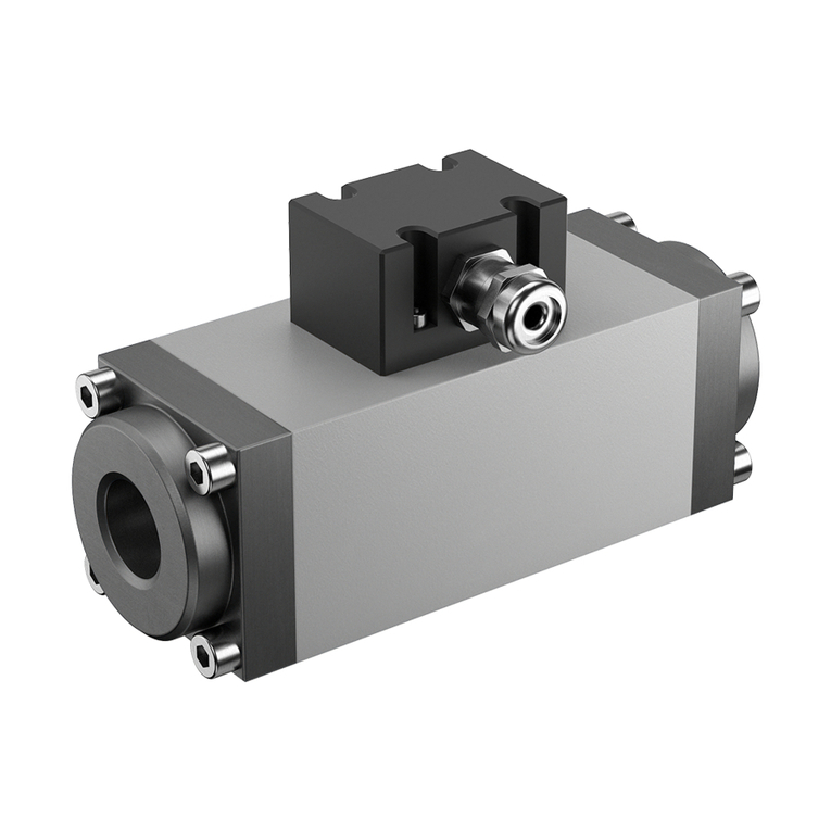
Table of contents
Other KRAL Measuring Instrument manuals

KRAL
KRAL OME Series User manual

KRAL
KRAL OME Series User manual

KRAL
KRAL OMG Series User manual

KRAL
KRAL BEM 200 User manual

KRAL
KRAL OMS Series User manual

KRAL
KRAL Volumeter OMG Series User manual

KRAL
KRAL OMP Series User manual

KRAL
KRAL BEM 150 User manual

KRAL
KRAL BEM 300 Series User manual

KRAL
KRAL Volumeter OMG 13 User manual