KRAL OMS Series User manual

Operating instructions
KRAL flowmeters.
Series OMS
High-viscosity liquids
OIO 31en-GB
Edition 2018-08
Original instructions
www.kral.at

Table of contents
1 About this document ..................................................... 3
1.1 General information .......................................................3
1.2 Target groups ................................................................3
1.3 Symbols.........................................................................3
1.3.1 Danger levels ....................................................3
1.3.2 Danger signs.....................................................4
1.3.3 Symbols in this document .................................4
1.4 Associated documents ..................................................4
2 Safety .............................................................................. 5
2.1 Proper use .....................................................................5
2.2 Foreseeable misuse ......................................................5
2.3 Obligations of the operator-owner .................................5
2.4 Dangers during transportation .......................................6
2.5 Dangers during storage .................................................6
2.6 Dangers during installation ............................................6
2.7 Dangers during removal ................................................6
2.8 Dangers during connection work ...................................6
2.9 Dangers during operation ..............................................6
2.10 Dangers during servicing...............................................7
2.11 Dangers during disposal................................................7
3 Identification................................................................... 8
3.1 Type code......................................................................8
3.2 Rating plate ...................................................................8
4 Technical data ................................................................ 9
4.1 Operating limits..............................................................9
4.2 Pressure pulsation.........................................................9
4.3 Maximum values............................................................9
4.4 Pick up...........................................................................9
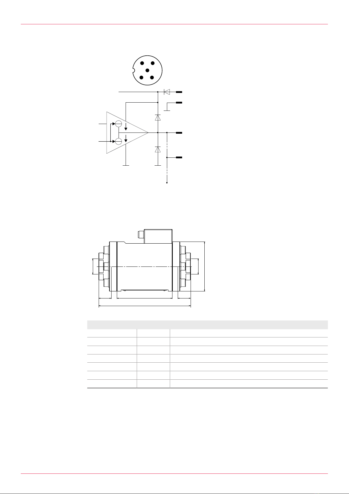
4.5 Pin assignment / Connection diagram.........................10
4.6 Dimensions and weights..............................................10
4.6.1 Pipe thread (BSPP thread) .............................10
5 Function description.................................................... 11
5.1 Structure ......................................................................11
5.2 Functional principle......................................................11
5.3 Signal generation.........................................................11
5.4 Recognition of flow direction........................................12
5.5 Temperature compensation (optional).........................12
6 Transportation, storage............................................... 12
6.1 Dangers during storage ...............................................12
6.2 Unpacking and checking the state of delivery .............12
6.3 Transporting flowmeters ..............................................12
6.4 Storing the flowmeter...................................................12
7 Installation, removal .................................................... 13
7.1 Dangers during installation ..........................................13
7.2 Dangers during removal ..............................................13
7.3 Installing the flowmeter................................................13
7.3.1 Protecting the flowmeter against soiling .........13
7.3.2 Installation types .............................................14
7.3.3 Installation recommendation ...........................15
7.3.4 Installing the flowmeter ...................................16
7.4 Installing the trace heating (optional)...........................16
7.5 Removing the flowmeter..............................................17
8 Connection ................................................................... 18
8.1 Dangers during connection work .................................18
8.2 Connecting the flowmeter to the pipe system ..............18
8.3 Connecting the pick up ................................................19
9 Operation........................................................................20
9.1 Dangers during operation ............................................20
9.2 Commissioning ............................................................20
9.2.1 Cleaning the pipe system ................................20
9.2.2 Checking the function ......................................20
9.2.3 Commissioning the flowmeter .........................20
9.3 Decommissioning.........................................................21
9.3.1 Switching off the flowmeter..............................21
9.4 Recommissioning.........................................................21
9.4.1 Recommissioning the flowmeter......................21
10 Maintenance...................................................................22
10.1 Required maintenance.................................................22
10.2 Recalibration of the flowmeter .....................................22
11 Disposal..........................................................................22
11.1 Dangers during disposal ..............................................22
11.2 Dismantling and disposing of the flowmeter ................22
12 Troubleshooting ............................................................24
12.1 Possible faults..............................................................24
12.2 Troubleshooting ...........................................................24
13 Appendix ........................................................................26
13.1 Tightening torque for screws with metric screw threads
and head contact surfaces...........................................26
13.2 Tightening torques for screw plugs with thread meas-
ured in inches and elastomer seal ...............................26
13.3 Contents of the Declaration of Conformity ...................26
2OIO 31en-GB Edition 2018-08 Operating instructions

1 About this document
1.1 General information
1 About this document
1.1 General information
These instructions form part of the product and must be kept for future reference. Furthermore please
observe the associated documents.
1.2 Target groups
The instructions are intended for the following persons:
oPersons who work with the product
oOperator-owners who are responsible for the use of the product
Information on the required qualification of the personnel is provided separately at the beginning of the
individual chapters in these instructions. The following table provides an overview.
Target group Activity Qualification
Transport per-
sonnel
Transportation,
unloading
Transport personnel are qualified personnel who carry out the trans-
portation of products properly due to their training, knowledge and
experience and on the basis of the relevant provisions. Transport
personnel recognize and avoid possible dangers and damage to
property that are connected with this activity.
Mobile crane
operators,
crane operat-
ors, forklift oper-
ators
Unloading, pos-
itioning
Mobile crane operators, crane operators and forklift operators are
qualified personnel who carry out work with cranes and forklifts
properly due to their training, knowledge and experience and on the
basis of the relevant provisions. Mobile crane operators, crane op-
erators and forklift operators recognize and avoid possible dangers
and damage to property that are connected with this activity.
Fitter Mounting, con-
nection
Fitters are qualified personnel who carry out the mounting work
properly due to their training, knowledge and experience and on the
basis of the relevant provisions. Fitters recognize and avoid pos-
sible dangers and damage to property that are connected with this
activity.
Electrician Electrical con-
nection
Electricians are qualified personnel who carry out work on electrical
equipment and installations properly due to their training, know-
ledge and experience and on the basis of the relevant provisions.
Electricians recognize and avoid possible dangers and damage to
property that are connected with this activity.
Trained person-
nel
Delegated task Trained personnel were instructed by the operator-owner in the task
delegated to them and the possible dangers arising through im-
proper behaviour.
Tab.1: Target groups
1.3 Symbols
1.3.1 Danger levels
Signal word Danger level Consequences of non-observance
DANGER Immediate threat of danger Serious personal injury, death
WARNING Possible threat of danger Serious personal injury, invalidity
CAUTION Potentially dangerous situation Slight personal injury
ATTENTION Potentially dangerous situation Material damage
Operating instructions OIO 31en-GB Edition 2018-08 3

1 About this document
1.4 Associated documents
1.3.2 Danger signs
Meaning Source and possible consequences of non-observance
Electrical voltage Electrical voltage causes serious physical injury or death.
Raised load Falling objects can result in serious physical injury or death.
kg
Heavy load Heavy loads can result in serious back problems.
Risk of slipping Discharging pumped liquid and oils on the foundation or
tread surfaces can cause falls with serious physical injury
or death.
Flammable substances Discharging pumped liquid and oils can be easily inflam-
mable and can result in serious burns.
Hot surface Hot surfaces can cause burns.
1.3.3 Symbols in this document
Meaning
Warning personal injury
Safety instruction
Request for action
1.
2.
3.
Multi-step instructions for actions
Action result
Cross-reference
1.4 Associated documents
oCalibration certificate (optional)
oDeclaration of conformity according to EU Directive 2006/42/EC
oManufacturer's declaration according to EU Directive 2014/68/EU
oCorresponding operating instructions for accessories
4OIO 31en-GB Edition 2018-08 Operating instructions

2 Safety
2.1 Proper use
2 Safety
2.1 Proper use
oUse the flowmeter solely for measuring the flow of liquids that do not contain any gas components
or solid particles.
oIf coarse soiling, solid particles in the liquid or abrasive fine particles occur during operation, the
flowmeter has to be protected additionally by a correspondingly dimensioned operating filter in the
pipe system.
oUse the flowmeter only within the operating limits specified on the rating plate and in the chapter
"Technical data". Deviating operating data can result in damage to the flowmeter. In the case of op-
erating data that do not agree with the specifications on the rating plate, please contact the manu-
facturer.
oStrong changes in the flow rate (for example rapid shutdown, pulsations, etc.) cause marked pres-
sure differences in the flowmeter and can damage the measuring unit. The pressure loss of the
flowmeter must not exceed the values shown in the chapter "Technical data".
2.2 Foreseeable misuse
oAny use that extends beyond the proper use or any other use is misuse.
oThe product is not suitable for pumping liquids outside the operational limits.
oAny bypassing or deactivation of safety equipment during operation is prohibited.
2.3 Obligations of the operator-owner
The operator-owner is the person who operates the product commercially or permits a third party to
use it and who bears the legal responsibility for the product, the protection of the personnel and third
parties during its operation.
The product is used in industrial applications. The operator-owner is therefore subject to the statutory
obligations concerning occupational health and safety.
In addition to the safety instructions in these instructions, the regulations on safety, accident prevention
and environmental protection respectively valid for the range of application of the product are to be ob-
served.
This results in the following obligations for the operator-owner:
oObserve the rules and regulations such as national standards, international standards and provi-
sions applicable at the site of use.
oObserve the obligations arising from occupational safety and from safety, accident protection and
environmental protection.
oDraw up a hazard assessment for the utilization of the product at the site of use.
oDraw up the operating guidelines for the operation of the product on the basis of the hazard assess-
ment.
oKeep the operating guidelines up-to-date during the entire operating life of the product, by ensuring
that the current version of the applicable rules and regulations are integrated.
oEnsure the qualification, instruction, information on dangers as well as regular training of the per-
sonnel.
oSpecify clear responsibilities for all work on the product, for example for the installation, operation,
maintenance, troubleshooting.
oKeep the operating instructions available at the site of use - also for future use.
oEnsure that the operating instructions as well as the associated documents are read, understood
and observed by the personnel.
oObserve the safety regulations for handling dangerous pumped liquids and comply with the safety
data sheets. Pumped liquids can, for example, be hot, poisonous, combustible and caustic.
oMake personal protective equipment available and instruct their use.
oEquip systems with an increased potential of danger with protective equipment and/or alarm equip-
ment. The failure of a component may not result in injury and/or damage to property.
oMaintain and check protective equipment and alarm equipment regularly.
oEnsure the technically flawless state of the product during its entire operating life.
Operating instructions OIO 31en-GB Edition 2018-08 5

2 Safety
2.4 Dangers during transportation
The following safety instructions must be observed:
oHave all work only carried out by authorized transport personnel.
oUse intact and correctly dimensioned hoisting equipment.
oEnsure that the means of transport is in a flawless state.
oEnsure that the centre of gravity of the load is taken into consideration.
oDo not stand under raised loads.
2.5 Dangers during storage
The following safety instructions must be observed:
oObserve the storage conditions.
2.6 Dangers during installation
The following safety instructions must be observed strictly:
oHave all work only carried out by authorized qualified personnel.
oDo not take apart the flowmeter.
2.7 Dangers during removal
The following safety instructions must be observed strictly:
oHave all work only carried out by authorized qualified personnel.
oEnsure that the collection tank for emitted liquids is sufficiently large.
oCollect any discharging pumped liquid safely and dispose of it in an environmentally compatible
manner in accordance with the applicable local regulations.
2.8 Dangers during connection work
The following safety instructions must be observed strictly:
oHave all the work on the flowmeter and pipe system only carried out by authorized qualified per-
sonnel.
oEnsure that solid particles cannot get into the flowmeter and pipe system.
oEnsure that mechanical connections are mounted free of stress.
oObserve the tightening torques.
oHave all the work on the electrical equipment only carried out by electricians.
oBefore beginning work on the flowmeter ensure that the electrical power supply is deenergized
and is secured against being switched back on.
oIf the insulation of the electrical cables or wires is damaged, disconnect the power supply immedi-
ately.
oThe connecting line of the pick up/temperature sensor connection is to be shielded and laid separ-
ately from the supply lines.
2.9 Dangers during operation
The following safety instructions must be observed strictly:
oHave all work only carried out by authorized qualified personnel.
oEnsure that the flowmeter is only operated within the operating limits.
oEnsure that during cooling down or heating up the flowmeter is only subjected to slow temperat-
ure changes.
oEnsure that existing safety equipment is not bypassed or activated during operation.
6OIO 31en-GB Edition 2018-08 Operating instructions

2 Safety
2.10 Dangers during servicing
The following safety instructions must be observed strictly:
oHave all work only carried out by authorized qualified personnel.
oTo ensure the measuring precision, the measuring unit may only be replaced by the manufac-
turer.
oBefore beginning work, let the flowmeter cool down slowly to the ambient temperature. Avoid
rapid temperature changes.
oPumped liquids can be hot, poisonous, combustible and caustic.
oObserve the tightening torques Ä Appendix,Page26.
oObserve the operating instructions and data sheets of the sensors.
2.11 Dangers during disposal
The following safety instructions must be observed strictly:
oCollect any discharging pumped liquid safely and dispose of it in an environmentally compatible
manner in accordance with the applicable local regulations.
oEnsure that the collection tank for emitted liquids is sufficiently large.
oNeutralize residues.
Operating instructions OIO 31en-GB Edition 2018-08 7

3 Identification
3.1 Type code
3 Identification
3.1 Type code
OMS-020.XBXXAX.0001
1
2
3
4
5
68
7 9
Fig.1: Type code
1Series
2Size
3Sensor equipment (pick up)
4Function of the sensor equipment
5Material of bearing
6Material of seal
7Mechanical connection
8Electrical connection
9Version index
Item Designation Description
1Series OMS Stainless steel
2Size Corresponds to the diameter of the large measur-
ing screw in [mm]
3Sensor equipment (pick up) X Special design
4Function of the sensor equipment B With recognition of flow direction
D With recognition of flow direction, with temperat-
ure compensation
X Special design
5Material of bearing X Special design
6 Material of seal X Special design
7 Mechanical connection A Thread connection BSPP
B Flange connection DIN
C Thread connection NPT
D Flange connection ANSI
E Flange connection JIS
F Flange connection SAE
X Special design
8Electrical connection X Special design
9Version index For internal administration
Tab.2: Type code
3.2 Rating plate
R
1 2 3
4567
Fig.2: Rating plate
1Serial number
2Construction year
3K-factor
4Preferred flow direction
5Max. temperature
6Series
7Max. pressure
8OIO 31en-GB Edition 2018-08 Operating instructions

4 Technical data
4.1 Operating limits
4 Technical data
4.1 Operating limits
The values specified on the rating plate apply, as well as the values on the calibration certificate if the
optional calibration of the flowmeter was ordered.
The permissible operating limits of individual values influence each other so that every application is
checked individually by the manufacturer when selecting the flowmeter.
If no operating data are provided by the orderer, standardized substitute operating data are used.
4.2 Pressure pulsation
p
[bar]
10 3020 40 t [ms]
30
10
20
0
p
[bar]
Fig.3: Pressure pulses
Strong pressure pulsations in the system can reduce the service life of the flowmeter.
4.3 Maximum values
The following table shows the respective maximum values that, however, may not occur simultan-
eously. In addition, the operating limits of the corresponding completion, of the sealing material and of
the pick up are to be observed.
Unit OMS-020
Flow rate
Qrated [l/min] 10
Qmin [l/min] 0.04
Max. pressure [bar] 400
Temperature
min - max [°C] -20 ... +80
Viscosity
min - max [mm2/s] 102 – 106
K-factor [P/l] 66000
Tab.3: Maximum values
4.4 Pick up
Unit OMS-020
Supply voltage UB[VDC] 10 – 29
Closed current [mA] < 20
Frequency range [Hz] 44 – 11000 (with K-factor 66000 P/l)
Electrical connection M12 socket connector, 5-pole, A-coding
Output Push-pull, driver stages
Short-circuit-proof Yes
Output current limiting [mA] 30 (per output)
Output low level [V] < 0.5 (@ 1mA),
1 (@10mA)
Output high level [V] Uhigh > 22.5 (@Ub = 24V, 1mA)
Uhigh > 22.0 (@Ub = 24V, 10mA)
Degree of protection IP 67
Tab.4: Pick up
Operating instructions OIO 31en-GB Edition 2018-08 9

4 Technical data
4.5 Pin assignment / Connection diagram
1
2 3
4
5
1
2/4
3
5
Fig.4: Pin assignment / Connection diagram
1+UB
2fB (signal OUT (push-pull))
3GND (0 V)
4fA (signal OUT (push-pull))
5Not connected
4.6 Dimensions and weights
4.6.1 Pipe thread (BSPP thread)
T T
L2
L1
D
G
G
Fig.5: Dimensional drawing pipe thread
GPipe thread
DOuter diameter
L1 Total length
L2 Length of the flowmeter without
connections
TMax. screw-in depth
Unit OMS-020
G [inch] 3/4
Pressure stage [bar] 400
D [mm] 84
L1 [mm] 156
L2 [mm] 94
T [mm] 21
Weight [kg] 6.0
Tab.5: Dimensions and weights - pipe thread connection
10 OIO 31en-GB Edition 2018-08 Operating instructions

5 Function description
5.1 Structure
5 Function description
5.1 Structure
1 42
5785
13
6
Fig.6: Structure of the flowmeter
1Connection mechanical 5O-ring
2Measuring housing 6Pole wheel
3Connection electrical 7Measuring screw large
4Pick-up 8Measuring screw small
5.2 Functional principle
Flowmeters belong to the group of rotating displacement meters as screw meters. The pumped liquid
makes the measuring unit rotate. The displacement effect results from the continuous filling, axial dis-
placement and discharge of the volumes that are formed by the measuring housing and measuring
unit. The measured pumped liquid flows around and lubricates all the rotating parts. Thanks to the dis-
placement principle, the flowmeter does not require inlet sections and smoothing sections at the feed
line and outlet.
Depending on the customer requirements, the flowmeters can be equipped with suitable end connec-
tions for connection to various flanges.
5.3 Signal generation
A pole wheel6 whose pole is sampled by a pick up4 is affixed at the end of the large measuring
screw7. This pick up generates a specific number of pulses per flow volume unit - depending on the
size and working point. This device-specific characteristic is called the K-factor (unit: Pulse/litre) and is
specified on the rating plate as well as the optional calibration certificate.
The preferred flow direction is specified on the rating plate and on the measuring housing2 of the flow-
meter. When this flow direction is observed, the pick up is located on the low-pressure end (outlet) in
the case of blocking.
Operating instructions OIO 31en-GB Edition 2018-08 11

6 Transportation, storage
5.4 Recognition of flow direction
In the case of systems with pressure pulsation a reversal of the flow direction can occur briefly. In order
to recognize the flow direction the flowmeter is equipped with a two-channel pick up. The flow direction
can be determined by means of the additional phase-shifted signal and then taken into account for the
calculation of the total values.
5.5 Temperature compensation (optional)
Flowmeters of the series OMS can additionally be equipped with a temperature sensor. The current
density of the flowing liquid can be calculated from the measured values of the temperature sensor by
using a density table stored in an external evaluation electronic unit. This allows standardised volume
measurement in which the displayed values are converted to a reference temperature that can be se-
lected freely. This ensures that measuring errors caused by changes in the density due to temperature
variations are avoided.
6 Transportation, storage
6.1 Dangers during storage
The following safety instructions must be observed:
oObserve the storage conditions.
6.2 Unpacking and checking the state of delivery
1. Upon delivery unpack the flowmeter and check it for damage during transportation.
2. Report damage during transportation immediately to the manufacturer.
3. Dispose of packaging material in accordance with the locally applicable regulations.
6.3 Transporting flowmeters
ATTENTION
Damage to equipment through improper transportation.
► Protect the flowmeter against damage, heat, sunlight, dust and moisture.
Transport the flowmeter in the original packaging.
6.4 Storing the flowmeter
The connections of the flowmeter are fitted with protective covers before being dispatched.
ATTENTION
Damage to equipment and corrosion if stored improperly and during longer standstills.
► Protect the flowmeter against damage, heat, sunlight, dust and moisture.
► Observe measures for storage.
Store cool and dry and protect against sunlight.
12 OIO 31en-GB Edition 2018-08 Operating instructions

7 Installation, removal
7.1 Dangers during installation
7 Installation, removal
7.1 Dangers during installation
The following safety instructions must be observed strictly:
oHave all work only carried out by authorized qualified personnel.
oDo not take apart the flowmeter.
7.2 Dangers during removal
The following safety instructions must be observed strictly:
oHave all work only carried out by authorized qualified personnel.
oEnsure that the collection tank for emitted liquids is sufficiently large.
oCollect any discharging pumped liquid safely and dispose of it in an environmentally compatible
manner in accordance with the applicable local regulations.
7.3 Installing the flowmeter
7.3.1 Protecting the flowmeter against soiling
Notice Soiling in the pipe system impairs the service life of the flowmeter. In order to protect the flowmeter
against soiling the manufacturer generally recommends the installation of an operating filter.
Personnel qualification: oFitter
Personal protective equipment: oWork clothing
oProtective gloves
oSafety boots
ATTENTION
Damage to device through solid particles in the pipe system.
► During welding work attach protective covers in front of the connecting flanges.
► Ensure when welding that welding beads and abrasive dust cannot get into the pipe system and
the flowmeter.
► Ensure that an operating filter is installed when the pipe system is flushed and cleaned using the
flowmeter.
1. Install the operating filter in front of the flowmeter, mesh width Ä Commissioning,Page20.
2. After the connecting work clean the pipe system thoroughly Ä Commissioning,Page20.
Operating instructions OIO 31en-GB Edition 2018-08 13

7 Installation, removal
7.3 Installing the flowmeter
7.3.2 Installation types
Flowmeters can be operated in different mounting positions.
Both flow directions are possible. The preferred flow direction is indicated on the rating plate by means
of a bright arrow Ä Identification,Page8.
12
3
4
Fig.7: Installation types
The arrow with dashed line identifies the preferred flow direction when an operating filter is used.
Installation type Properties
1oWithout bypass
oWith or without operating filter
oSmall space requirements
oDismantling of the flowmeter only with
operation interruption
2oManual bypass
oWith or without operating filter
oManual opening of the bypass
oDismantling of the flowmeter only with
operation interruption
3oBypass with 3 shut-off valves for flange
connection
oWith or without operating filter
oDismantling of the flowmeter without op-
eration interruption
4oBypass with 3 shut-off valves for pipe
thread connection
oWith or without operating filter
oDismantling of the flowmeter without op-
eration interruption
oMinimal higher pressure loss
Tab.6: Installation types
14 OIO 31en-GB Edition 2018-08 Operating instructions

7 Installation, removal
7.3 Installing the flowmeter
7.3.3 Installation recommendation
In order to avoid measuring errors observe the following recommendations of the manufacturer when
installing the flowmeter in the pipe system.
X
X
X
Preferred installation variant:
- Install the flowmeter vertically.
- Route the flow from the bottom upwards.
Recommendations for alternative installation variants
Alternative installation variant:
- Install the flowmeter vertically.
- Route the flow from the top downwards.
- Route the piping at the outlet upwards.
Source for measuring error:
- Lack of counter-pressure at the outlet through
downward routing of the piping.
Alternative installation variant:
- Install the flowmeter horizontally.
- Route the piping at the outlet upwards.
Source for measuring error:
- Formation of an air pocket through the
installation of the flowmeter at the highest point
of the piping.
Recommendation:
- Carefully vent the pipe system during
commissioning.
Source for measuring error:
- Gas inclusions in the pipe system
Operating instructions OIO 31en-GB Edition 2018-08 15

7 Installation, removal
7.4 Installing the trace heating (optional)
7.3.4 Installing the flowmeter
Personnel qualification: oFitter
Personal protective equipment: oWork clothing
oProtective gloves
oSafety boots
ATTENTION
Measuring error through air pocket in the flowmeter.
► During installation ensure that the flowmeter is not installed at the highest point in the pipe system.
ATTENTION
Measuring error through a lack of counter-pressure.
► During the installation ensure that the piping at the outlet of the flowmeter runs upwards or that the
pipe diameter is reduced through a reducer so that the liquid generates a counter-pressure.
During the installation of the flowmeter observe the recommendations for the installation variants
and avoid error sources.
7.4 Installing the trace heating (optional)
The flowmeter can optionally be equipped with a trace heating system provided by the customer. The
manufacturer recommends a heating system at high-viscosity liquids that do not flow sufficiently if not
heated.
Notice Before installing trace heating provided by the customer, contact the manufacturer.
Personnel qualification: oFitter
Personal protective equipment: oWork clothing
oProtective gloves
oSafety boots
ATTENTION
Defective components through the maximum temperature being exceeded.
► Do not heat the pick ups, socket connectors and connecting cables above the maximum permiss-
ible temperature Ä Technical data,Page9.
1
1
3
4
2
5
X
Fig.8: Flowmeter with trace heating
1Thermal insulation
2Flowmeter
3Pick up
4Heating line
5Piping
XArea necessarily without thermal
insulation
Wind the heating line4 around the piping5. Ensure that the pick up3, junction box and associ-
ated cables are not thermally insulated. The areaX must remain free of thermal insulation.
16 OIO 31en-GB Edition 2018-08 Operating instructions

7 Installation, removal
7.5 Removing the flowmeter
Personnel qualification: oFitter
oElectrician
Personal protective equipment: oWork clothing
oFace protection
oProtective gloves
oSafety boots
Aids: oCollection tank
DANGER
Risk of death resulting from electric shock.
► Ensure that the electrical power supply is de-energized and is secured against being switched
back on.
► Observe the operating instructions of the electrical components.
DANGER
Risk of death through emitted pumped liquid.
Pumped liquids can be hot, poisonous, combustible and caustic and can spray out under high pres-
sure.
► Wear personal protective equipment during all the work. Ensure face protection.
► Before beginning work, let the flowmeter cool down to the ambient temperature.
► Ensure that the flowmeter is depressurized.
► Collect any discharging pumped liquid safely and dispose of it in an environmentally compatible
manner in accordance with the applicable local regulations.
Requirement:
üSystem switched off
üDisconnect the system from the power supply and secure it against being switched back on
üFlowmeter cooled down to the ambient temperature
1. Drain the pipe system or divert the pumped liquid via bypass.
2. Remove the flowmeter.
3. Attach protective covers in front of connecting flanges.
4. For storage of the flowmeter Ä Transportation, storage,Page12.
Operating instructions OIO 31en-GB Edition 2018-08 17

8 Connection
8.1 Dangers during connection work
8 Connection
8.1 Dangers during connection work
The following safety instructions must be observed strictly:
oHave all the work on the flowmeter and pipe system only carried out by authorized qualified per-
sonnel.
oEnsure that solid particles cannot get into the flowmeter and pipe system.
oEnsure that mechanical connections are mounted free of stress.
oObserve the tightening torques.
oHave all the work on the electrical equipment only carried out by electricians.
oBefore beginning work on the flowmeter ensure that the electrical power supply is deenergized
and is secured against being switched back on.
oIf the insulation of the electrical cables or wires is damaged, disconnect the power supply immedi-
ately.
oThe connecting line of the pick up/temperature sensor connection is to be shielded and laid separ-
ately from the supply lines.
8.2 Connecting the flowmeter to the pipe system
Personnel qualification: oFitter
Personal protective equipment: oWork clothing
oProtective gloves
oProtective helmet
oSafety boots
Aids: oHoisting equipment
ATTENTION
Damage to device through mechanical stress.
► Ensure that the flowmeter is mounted free of mechanical stresses in the pipe system.
► Observe the tightening torques.
ATTENTION
Damage to device through solid particles in the pipe system.
► During welding work attach protective covers in front of the connecting flanges.
► Ensure when welding that welding beads and abrasive dust cannot get into the pipe system and
the flowmeter.
► Ensure that an operating filter is installed when the pipe system is flushed and cleaned using the
flowmeter.
ATTENTION
Damage to device when the pipe threading is screwed in too far.
► Observe the thread length of the flowmeter.
► Use a standard cutting ring screw connection.
18 OIO 31en-GB Edition 2018-08 Operating instructions

8 Connection
8.3 Connecting the pick up
Notice The screw-in length of the piping may not exceed the threaded length of the flowmeter, since the flow
cross-section is narrowed and internal components can be damaged.
1. Remove the protective covers and store them.
2. Place the piping in position and support the weight of the piping.
3. Install the flowmeter stress-free into the pipe system. In the process take the preferred flow direc-
tion into account and ensure that the connections of the pick up remain accessible.
4. Check the linear offset, lateral offset and angular offset and correct if necessary. If the screws
tighten easily, this is a sure sign that the installation is stress-free.
5. Tighten the connecting screws crosswise with torque Ä Appendix,Page26.
8.3 Connecting the pick up
The flowmeter is equipped with a two-channel pick up.
1. Connect the pick up with a 5-pin socket connector. Take the pin assignment into account Ä
Technical data,Page9.
2. Tighten the fastening screw at socket connector only hand-tight.
3. Earth the flowmeter carefully.
Operating instructions OIO 31en-GB Edition 2018-08 19

9 Operation
9.1 Dangers during operation
9 Operation
9.1 Dangers during operation
The following safety instructions must be observed strictly:
oHave all work only carried out by authorized qualified personnel.
oEnsure that the flowmeter is only operated within the operating limits.
oEnsure that during cooling down or heating up the flowmeter is only subjected to slow temperat-
ure changes.
oEnsure that existing safety equipment is not bypassed or activated during operation.
9.2 Commissioning
9.2.1 Cleaning the pipe system
Notice Soiling in the pipe system impairs the service life of the flowmeter. In order to protect the flowmeter
against soiling the manufacturer generally recommends the installation of an operating filter.
ATTENTION
Damage to device through usage of an incorrect flushing liquid.
► Under no circumstances may water or superheated steam be used to flush the pipe system.
Flushing via bypass:
Close the shut-off devices before and after the flowmeter.
- or -
Flushing via flowmeter:
Install the operating filter before the flowmeter. In this case select the mesh width of the operating
filter in accordance with the pumped liquid.
9.2.2 Checking the function
1. Check the flow direction of the flowmeter.
2. Check the installation of the pick up and optional temperature sensor.
3. Check for leaks at the pipe thread/connecting flange.
4. Check the electrical installation.
5. Check the power supply.
9.2.3 Commissioning the flowmeter
ATTENTION
Increased wear and/or blockade through solid particles or abrasive fine particles in the liquid.
► Protect the flowmeter through correspondingly dimensioned operating filters in the pipe system.
ATTENTION
Measuring error when the pressure drops below the minimum pressure outlet at the outlet.
► Ensure that sufficient counter-pressure exists at the outlet by routing the piping upwards.
ATTENTION
Measuring error through gas inclusion in the pipe system.
► Before commissioning, make sure that the flowmeter is filled.
► Vent the pipe system.
20 OIO 31en-GB Edition 2018-08 Operating instructions
Other manuals for OMS Series
1
This manual suits for next models
2
Table of contents
Other KRAL Measuring Instrument manuals

KRAL
KRAL BEM 300 Series User manual

KRAL
KRAL BEM 100 User manual

KRAL
KRAL OMH Series User manual

KRAL
KRAL Volumeter OMG Series User manual

KRAL
KRAL BEM 150 User manual

KRAL
KRAL OMP Series User manual

KRAL
KRAL BEM 500 Series User manual

KRAL
KRAL OME Compact Series User manual

KRAL
KRAL OME Series User manual

KRAL
KRAL BEM 200 User manual