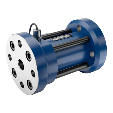
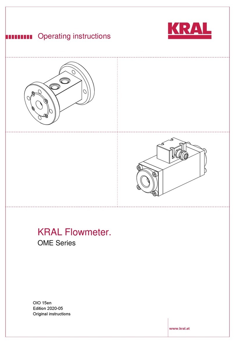
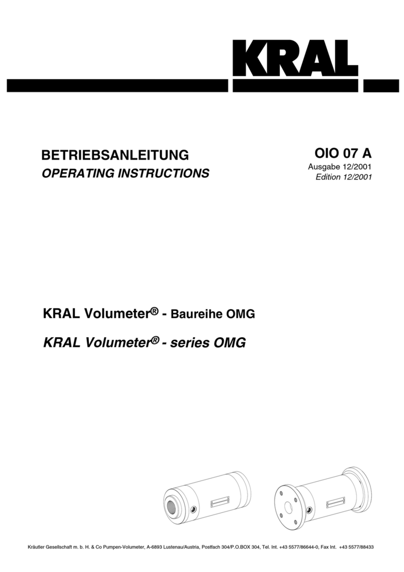
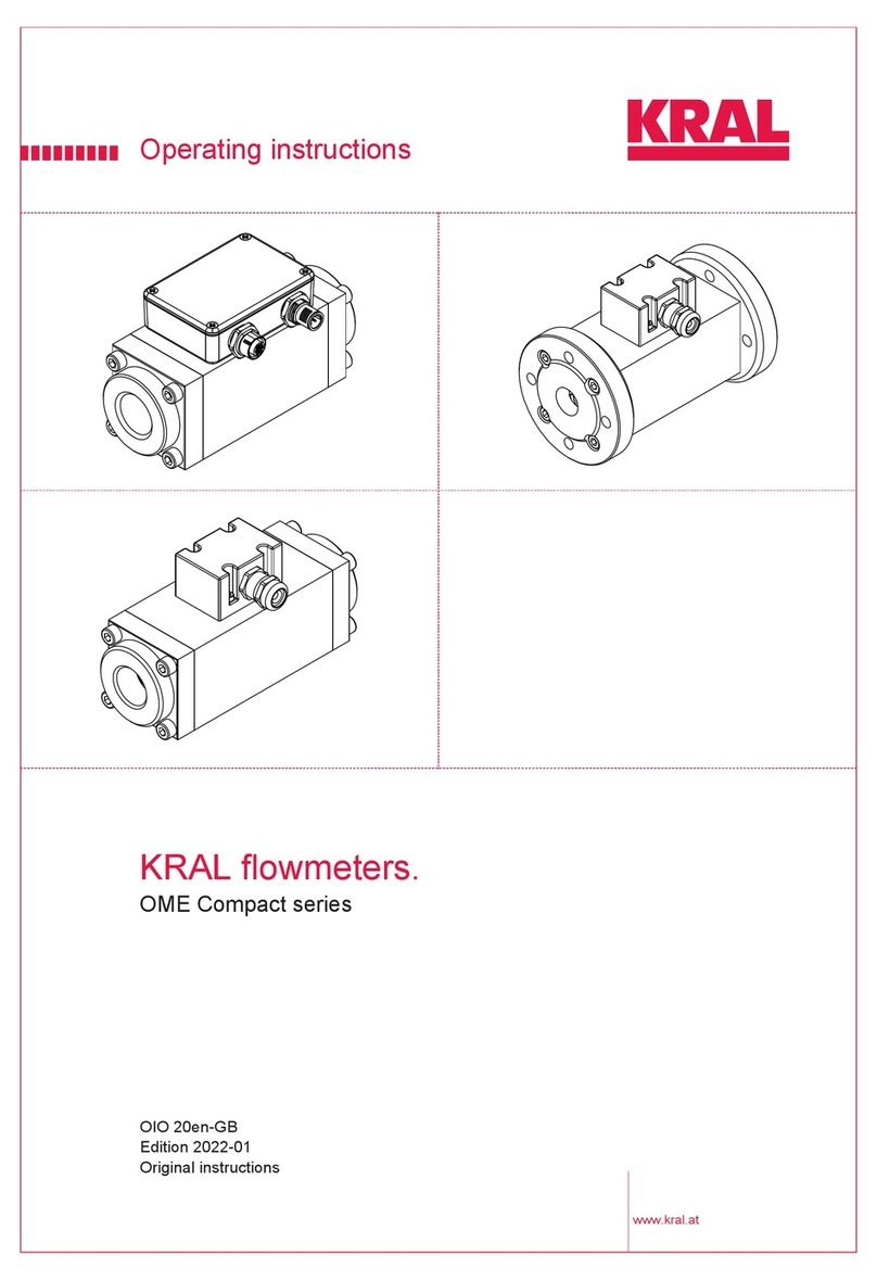
KRAL Volumeter OMG 13 User manual

www.kral.at
Operating Instructions
KRAL Flowmeter.
OMG Series
OIO 14en
Edition 07/2017
Original instructions

2 OIO 14en Edition 07/2017 Operating Instructions
Table of contents
KRAL Flowmeter – OMG Series
About this document
□General information 3
□Target groups 3
□Symbols 3
□Danger levels 3
□Associated documents 4
Safety
□Proper use 5
□Safety information 5
Labelling
□Type code 6
□Rating plate 7
Technical data
□Operational limits 8
▪Load due to pressure pulsation 8
▪Maximum values 8
▪Substitute operating data 10
□Sound pressure level 10
□Dimensions and weights 10
▪OMG with BSPP thread 10
▪OMG with DIN flange 11
□Load-bearing capacity 12
▪Load-bearing capacity OMG 13 12
▪Load-bearing capacity OMG 20 13
▪Load-bearing capacity OMG 32 14
▪Load-bearing capacity OMG 52 15
▪Load-bearing capacity OMG 68 16
▪Load-bearing capacity OMG100 17
▪Load-bearing capacity OMG140 18
Heating system
□Electric heating system 19
□Fluid heating system 20
□Trace heating system 20
Function description
□Description 21
□Roller bearings 22
□Signal generation 22
□Linearization 22
□Temperature compensation 23
□Flow direction detection 23
□Junction box 23
Transportation, storage and disposal
□Unpacking and checking the state of
delivery 24
□Lifting the flowmeter 24
□Storage 24
□Preservation 25
▪Preserving the flowmeter 25
▪Removing the preservation 25
□Disposal 26
Installation, removal and connection
□Safety instructions for installation and
removal 27
□Installing the flowmeter 27
▪Installation types 27
▪Preferred installation variant 28
▪Recommendations for alternative
installation variants 28
▪Protect the flowmeter against soiling 29
▪Connecting the flowmeter to the pipe
system 29
□Electrical connection 30
▪Safety instructions for electrical
installation 30
▪Connection for the pick ups 30
□Removing the flowmeter 30
Operation
□Commissioning 32
▪Cleaning the pipe system 32
▪Checking the function 32
▪Commissioning the flowmeter 32
□Switching off the flowmeter 33
▪Safety instruction for switching off the
flowmeter 33
▪Switching off the flowmeter 33
□Recommissioning the flowmeter 33
Maintenance
□Safety instructions on maintenance 34
□Required maintenance 34
□Re-calibration of the flowmeters 34
□Mounting instructions OMG 13 35
▪Removing seals and bearings 35
▪Installing seals and bearings 36
□Mounting instructions OMG 20/32 37
▪Removing seals and bearings 37
▪Installing seals and bearings 38
□Mounting instructions OMG 52/68 39
▪Removing seals and bearings 39
▪Installing seals and bearings 41
□Mounting instructions OMG100/140 42
▪Removing seals and bearings 42
▪Installing seals and bearings 43
Troubleshooting
□Possible faults 44
□Troubleshooting 44
Appendix
□General drawings 46
□Parts list 50
□Accessories 51
▪Junction box 51
▪Mounting and connecting the
junction box 52
▪Connecting the extension cable 53
□Tightening torques 53
□Contents of the EC Declaration of
Conformity 54
□Notes 55
Operating Instructions OIO 14en Edition 07/2017 3
General information
About this document
About this doc ument General information
The operating instructions form part of the KRAL Flowmeter and must be kept for future reference.
Furthermore please observe the associated documents.
Target groups
Symbols
Danger levels
Target group Tasks
Operator-owner □Keep these instructions available at the site of use for future
reference.
□Ensure that employees read and observe these instructions and the
associated documents, in particular the safety instructions and
warnings.
□Observe additional system-specific directives and regulations.
Specialist personnel, fitters □Read, observe and follow these instructions and the associated
documents, in particular the safety instructions and warnings.
Symbol Meaning
Warning personal injury
Notice
Action steps mechanical installation
Action steps electrical installation
Check or fault table
Request for action
Warning Danger level Consequences of non-observance
Danger Immediate threat of danger Serious personal injury, death
Warning Possible threat of danger Serious personal injury, invalidity
Caution Potentially dangerous situation Slight personal injury
Caution Potentially dangerous situation Material damage

4 OIO 14en Edition 07/2017 Operating Instructions
Associated documents
About this document
Associated documents
Calibration certificate
Declaration of conformity according to EU Directive 2006/42/EC
Manufacturer's declaration as per EU Directive 2014/34/EU
ATEX supplementary instructions for operation in areas at risk of explosions
Manufacturer's declaration as per EU Directive 2014/68/EU
Corresponding operating instructions for pick ups
Corresponding operating instructions for temperature sensor
Corresponding operating instructions for electronic equipment

Operating Instructions OIO 14en Edition 07/2017 5
Proper use
Safety
Safety Proper use
□Use flowmeters of the OMG series solely for flow measurement of lubricating liquids that are
chemically neutral and do not contain any gas or solids content.
□Flowmeters require the operation with clean liquids. If coarse soiling, solid particles in the liquid or
abrasive fine particles occur during operation, the flowmeter has to be protected additionally by a
correspondingly dimensioned operating filter in the pipe system, see "Cleaning the pipe system",
page 32.
□Only use flowmeters within the operational limits specified on the rating plate and in the "Technical
data" section. Deviating operating data can result in damage to the flowmeter. In the case of
operating data that does not agree with the specifications on the rating plate, please contact the
manufacturer.
□Strong changes to the flow rate (e.g. rapid shutdown, pulsations ...) cause marked pressure
differences on the flowmeter and can damage the measuring unit.
▪The pressure loss of the flowmeter must not exceed the values given in the chapter "Technical
data", see "Load-bearing capacity", page 12.
Safety information
The following safety instructions must be observed:
□No liability is accepted for damage arising through non-observance of the operating
instructions.
▪Read the operating instructions carefully and observe them.
▪The operator-owner is responsible for the observance of the operating instructions.
▪Installation, removal and installation work may only be carried out by specialist personnel.
□Flowmeters wear to different degrees depending on the respective operating conditions
(pulsations, temperature, …).
▪Do not continue to use flowmeters that are operated contrary to specifications or after damage.
▪Check the flowmeters regularly.
▪Shut down damaged flowmeters and replace worn flowmeters immediately.
□In order for the warranty to remain valid, corrective maintenance carried out during the
warranty period requires the express permission of the manufacturer.
□Observe the general regulations for the prevention of accidents as well as the local safety
and operating instructions.
□Observe the valid national and international standards and specifications of the installation
location.
□In case of systems with an increased potential of danger to humans and/or machines the
failure of a flowmeter may not lead to injuries or damage to property.
▪Always equip systems with an increased potential of danger with alarm equipment and/or
bypass.
▪Maintain and check the protective/alarm equipment regularly.
□The pumped liquids can be dangerous (e.g. hot, dangerous to health, poisonous,
combustible). Observe the safety conditions for handling dangerous materials.
□Pumped liquids can be subject to pressure and can cause damage and/or personal injury
should leaks occur.

6 OIO 14en Edition 07/2017 Operating Instructions
Type code
Labelling
Labelling Type code
1Series
2Size
3Sensor technology
4Function of sensor technology
5Material of bearing
6Material of seal
7Mechanical connection
8Electrical connection
9Version index
Fig. 1 Type code
Item Designation Description
1Series OMG: Universal
2Size Corresponds to the diameter of the measuring screw large in [mm]
3Sensor technology B: BEG 43
C: BEG 44
D: BEG 45
E: BEG 45 + BEV 13
F: BEG 47
G: BEG 53
H: BEG 54
X: Special design
4Function of sensor
technology
A: Without flow direction detection
B: With flow direction detection
C: Without flow direction detection, with temperature compensation
D: With flow direction detection, with temperature compensation
X: Special design
5Material of bearing A: Steel
B: Hybrid
X: Special design
6Material of seal A: FPM (FKM)
B: FFPM
C: Low temperature FPM
D: EPDM
X: Special design
7Mechanical
connection
A: Pipe thread connection BSPP
B: Flange connection DIN
C: Pipe thread connection NPT
D: Flange connection ANSI
E: Flange connection JIS
F: Flange connection SAE
X: Special design
OMG-020.CABABA.0001
3
4
5
2
7
68
9
1

Operating Instructions OIO 14en Edition 07/2017 7
Rating plate
Labelling
Rating plate
8Electrical
connection
A: Loose cable head
B: Cable gland junction box
X: Special design
9Version index For internal administration
1Serial number
2Construction year
3K-factor
4Preferred flow direction
5Maximum temperature
6Type
7Maximum pressure
Fig. 2 Rating plate
Item Designation Description
R
123
4
5
6
7
®

8 OIO 14en Edition 07/2017 Operating Instructions
Operational limits
Technical data
Technic al data Operational limits
The values specified on the rating plate and the calibration certificate apply. The permissible operational
limits of individual values influence each other so that every application is checked individually by the
manufacturer when selecting the flowmeter.
If no operating data are provided by the orderer, standardized substitute operating data are used.
Load due to pressure pulsation
Maximum values
The following table shows the respective maximum values that, however, may not occur simultaneously.
In addition, the operational limits of the corresponding end connection, of the sealing material of the pick
up and of the temperature sensor are to be observed.
Tab. 1 Maximum values
Tab. 2 Additional maximum values when BEG 43D is used
Strong pressure pulses in the system can reduce the lifetime of
the flowmeter.
Fig. 1 Pressure pulses
OMG 13 OMG 20 OMG 32 OMG 52 OMG 68 OMG100 OMG140
Flow rate
Qmax [l/min] 15 45 150 525 1050 3000 7 500
Qnom 10 30 100 350 700 2000 5000
Qmin 0.1 0.3 13.5 720 50
Pressure max. [bar] 250 160 100 40
Temperature
min.–max. [° C] -20...+200
Viscosity
min.–max. [mm2/s] 1 – 1000000
Measuring
chamber
volume
[ml/U] 1.64 6.25 25.6 112.7 251.3 833.3 2259.9
Rotation speed
n (Qmax)[min-1]9120 7 200 5850 4658 4182 3600 3 318
n (Qnom)6090 4 800 3900 3105 2784 2400 2214
n (Qmin)61 48 39 31 28 24 22
K1 OMG 13 OMG 20 OMG 32 OMG 52 OMG 68 OMG100 OMG140
Pole number 246810 14 20
K-factor [P/l] 1216 640 234 71.0 39.8 16.8 8.85
Milliliters/pulse [ml/P] 0.822 1.56 4.27 14.08 25.13 59.52 112.99
Pulse frequency
f1 (Qmax)[Hz] 304 480 585 621 697 840 1106
f1 (Qnom)203 320 390 414 464 560 738
f1 (Qmin)2.0 3.2 3.9 4.1 4.6 5.6 7.4
10 3020 40 t [ms]
30
10
20
0
p
[bar]

Operating Instructions OIO 14en Edition 07/2017 9
Technical data
Tab. 3 Additional maximum values when BEG 44 is used
Tab. 4 Additional maximum values when BEG 45 is used
Tab. 5 Additional maximum values when BEG 47D is used
Tab. 6 Additional maximum values when BEG 53A or BEG 54A is used
K2 OMG 13 OMG 20 OMG 32 OMG 52 OMG 68 OMG100 OMG140
Pole number 4812 16 20 28 40
K-factor [P/l] 2432 1280 468 142 79.6 33.6 17.7
Milliliters/pulse [ml/P] 0.411 0.782 2.14 7.04 12.56 29.76 56.50
Pulse frequency
f2 (Qmax)[Hz] 608 960 1170 1243 1393 1680 2213
f2 (Qnom)405 640 780 828 929 1120 1475
f2 (Qmin)4.1 6.4 7.8 8.3 9.3 11.2 14.8
K3 OMG 13 OMG 20 OMG 32 OMG 52 OMG 68 OMG100 OMG140
Pole number 12 16 26 34 42 48 50
K-factor [P/l] 7296 2560 1014 302 167 57.6 22.1
Milliliters/pulse [ml/P] 0.137 0.391 0.99 3.31 5.98 17.36 45.20
Pulse frequency
f3 (Qmax)[Hz] 1824 1920 2535 2640 2927 2880 2763
f3 (Qnom)1216 1280 1690 1760 1949 1920 1842
f3 (Qmin)12.2 12.8 16.9 17.6 19.5 19.2 18.4
Observe the flow range: If the value lies below Qmin, refer to the
operating instructions of the corresponding pick-up
K1 OMG 13 OMG 20 OMG 32 OMG 52 OMG 68 OMG100 OMG140
Pole number 246810 14 20
K-factor [P/l] 1216 640 234 71.0 39.8 16.8 8.85
Milliliters/pulse [ml/P] 0.822 1.56 4.27 14.08 25.13 59.52 112.99
Pulse frequency
f1 (Qmax)[Hz] 304 480 585 621 697 840 1106
f1 (Qnom)203 320 390 414 464 560 738
f1 (Qmin)2.0 3.2 3.9 4.1 4.6 5.6 7.4
K4 OMG 13 OMG 20 OMG 32 OMG 52 OMG 68 OMG100 OMG140
Pole number 12 16 26 34 42 73 102
K-factor [P/l] 7296 2560 1014 302 167 87.6 45.1
Milliliters/pulse [ml/P] 0.137 0.391 0.986 3.311 5.988 11.416 22.173
Pulse frequency
f4 (Qmax)[Hz] 1824 1920 2535 2643 2923 4380 5638
f4 (Qnom)1216 1280 1690 1762 1948 2920 3758
f4 (Qmin)12.2 12.8 16.9 17.6 19.5 29.2 37.6

10 OIO 14en Edition 07/2017 Operating Instructions
Sound pressure level
Technical data
Substitute operating data
The following table shows standardized values for the flow rate, temperature and viscosity. These
values can be used at the same time as maximum values without impairing the service life of the
flowmeter. In addition, the operational limits of the corresponding end connection, of the sealing material
of the pick up and of the temperature sensor are to be observed.
Tab. 7 Substitute operating data
Sound pressure level
The sound pressure level of the flowmeter amounts to less than 70 dB(A).
Dimensions and weights
OMG with BSPP thread
Tab. 8 Dimensions and weights – pipe thread connection
OMG 13 OMG 20 OMG 32 OMG 52 OMG 68 OMG100 OMG140
Flow rate
Qmax [l/min] 10 30 100 350 700 2000 5 000
Qnom 10 30 100 350 700 2000 5000
Qmin 0.2 0.6 2 7 14 40 100
Pressure max. [bar] 250 160 100 40
Temperature
min.–max. [° C] -20...+120
Viscosity
min.–max. [mm2/s] 1 – 200
G
M18x1
G1/4"
D
L1
L2
T
Pipe thread
Pick up hole
Temperature sensor
hole
Outer diameter
Total length
Flowmeter length
without connections
Screw-in depth max.
Fig. 2 Dimensioned drawing OMG with pipe thread
OMG 13 OMG 20 OMG 32 OMG 52 OMG 68 OMG100 OMG140
G[inch] 1/2 3/4 11 1/2 2 4 6
Pressure
stage
[bar] 250 250 250 160 100 40 40
D[mm] 90 74 104 118 138 188 267
L1 [mm] 145 145 215 295 355 480 645
L2 [mm] 94 145 215 240 295 400 537
T[mm] 16 16 18 27.5 30 40 54
Weight [kg] 4.6 4.1 11 18 29 70 180
L1
L2
D
G
M18x1
G1/4"
T T

Operating Instructions OIO 14en Edition 07/2017 11
Dimensions and weights
Technical data
OMG with DIN flange
* Screw-in depth is not equal to L3, but rather amounts to 17 mm
Tab. 9 Dimensions and weights – DIN flange connection
DN
M18x1
G1/4"
D
L1
L2
L3
TK
Nominal diameter
flange
Pick up hole
Temperature sensor
hole
Outer diameter
Total length
Flowmeter length
without connections
Flange thickness
Pitch circle
Fig. 3 Dimensioned drawing OMG with DIN flange
OMG 13 OMG 20 OMG 32
DN 15 15 15 20 15 15 32 25 25
Pressure
stage
[bar] 40 160 250 40 160 250 40 160 250
D[mm] 95 105 130 105 105 130 140 140 150
L1 [mm] 145 145 145 185 185 195 265 265 275
L2 [mm] 94 94 94 145 145 145 215 215 215
L3 [mm] 25.5* 25.5* 25.5 20 20 25 25 25 30
TK [mm] 65 75 90 75 75 90 100 100 105
Weight [kg] 4.7 4.8 6.0 6.0 6.0 8.1 16 16 19
OMG 52 OMG 68 OMG100 OMG140
DN 40 40 50 50 100 100 150 150
Pressure
stage
[bar] 40 160 40 100 16 40 16 40
D[mm] 150 170 165 195 220 235 285 300
L1 [mm] 285 295 340 355 450 460 600 610
L2 [mm] 240 240 295 295 400 400 537 537
L3 [mm] 22.5 27.5 22.5 30 25 30 31.5 36.5
TK [mm] 110 125 125 145 180 190 240 250
Weight [kg] 21 23 31 37 65 70 170 180
L3
D
TK
G1/4"
DN
M18x1
L3 L2
L1

12 OIO 14en Edition 07/2017 Operating Instructions
Load-bearing capacity
Technical data
Load-bearing capacity
Load-bearing capacity OMG 13
The values apply for lubricating liquids at temperatures of up to 120 °C. Abrasive and aggressive liquids
reduce the durability.
AShort-time operation
BContinuous operation
CPressure loss
DFlow rate
EQnom
20
18
16
14
12
2
4
6
8
10
0
A
B
1000 h
30000 h
10000 h
5000 h
100000
5
10
50
200
500
1000
2000
5000
10000
50000
100
[mm2/s]
C
[bar]
[bar]
C2
3
0
1
100000
5000
10000
50000
5
10
50
200
500
1000
2000
100
[mm2/s]
234 109
8
7
65
0,1 115
14
13
12
11
E
D
[l/min]
10050 150
D
[l/min]
50
45
40
30
25
20
1510
51 35
3,52,5
1,50,5
0,1 4,5 5
1 2 3 4
[%] [%]
1

Operating Instructions OIO 14en Edition 07/2017 13
Load-bearing capacity
Technical data
Load-bearing capacity OMG 20
The values apply for lubricating liquids at temperatures of up to 120 °C. Abrasive and aggressive liquids
reduce the durability.
AShort-time operation
BContinuous operation
CPressure loss
DFlow rate
EQnom
20
18
16
14
12
2
4
6
8
10
0
A
B
1000 h
30000 h
10000 h
5000 h
100000
5
10
50
200
500
1000
2000
5000
10000
50000
100
[mm2/s]
C
[bar]
[bar]
C
2
3
0
1
100000
5000
10000
50000
5
10
50
200
500
1000
2000
100
[mm2/s]
6912 3027
24
21
1815
0,3 345
42
39
36
33
E
D
[l/min]
10050 150
D
[l/min]
50
45
40
30
25
20
1510
51 35
10,57,5
4,51,5
0,3 13,5 15
3 6 9 12
[%] [%]
1

14 OIO 14en Edition 07/2017 Operating Instructions
Load-bearing capacity
Technical data
Load-bearing capacity OMG 32
The values apply for lubricating liquids at temperatures of up to 120 °C. Abrasive and aggressive liquids
reduce the durability.
AShort-time operation
BContinuous operation
CPressure loss
DFlow rate
EQnom
20
18
16
14
12
2
4
6
8
10
0
A
B
1000 h
30000 h
10000 h
5000 h
100000
5
10
50
200
500
1000
2000
5000
10000
50000
100
[mm2/s]
C
[bar]
[bar]
C
2
3
0
1
100000
5000
10000
50000
5
10
50
200
500
1000
2000
100
[mm2/s]
20 30 40 10090
80
70
6050
110 150
140
130
120
110
E
D
[l/min]
10050 150
D
[l/min]
50
45
40
30
25
20
1510
51 35
3525
155
1 45 50
10 20 30 40
[%] [%]
1

Operating Instructions OIO 14en Edition 07/2017 15
Load-bearing capacity
Technical data
Load-bearing capacity OMG 52
The values apply for lubricating liquids at temperatures of up to 120 °C. Abrasive and aggressive liquids
reduce the durability.
AShort-time operation
BContinuous operation
CPressure loss
DFlow rate
EQnom
20
18
16
14
12
2
4
6
8
10
0
A
B
1000 h
30000 h
10000 h
5000 h
100000
5
10
50
200
500
1000
2000
5000
10000
50000
100
[mm2/s]
C
[bar]
[bar]
C2
3
0
1
100000
5000
10000
50000
5
10
50
200
500
1000
2000
100
[mm2/s]
70 105 140 350315
280
245
210175
3,5 35 525
490
455
420
385
E
D
[l/min]
10050 150
D
[l/min]
50
45
40
30
25
20
1510
51 35
122,587,5
52,517,5
3,5 157,5 175
35 70 105 140
[%] [%]
1

16 OIO 14en Edition 07/2017 Operating Instructions
Load-bearing capacity
Technical data
Load-bearing capacity OMG 68
The values apply for lubricating liquids at temperatures of up to 120 °C. Abrasive and aggressive liquids
reduce the durability.
AShort-time operation
BContinuous operation
CPressure loss
DFlow rate
EQnom
20
18
16
14
12
2
4
6
8
10
0
A
B
1000 h
30000 h
10000 h
5000 h
100000
5
10
50
200
500
1000
2000
5000
10000
50000
100
[mm2/s]
C
[bar]
[bar]
C
2
3
0
1
100000
5000
10000
50000
5
10
50
200
500
1000
2000
100
[mm2/s]
140 210 280 700630
560
490
420350
770 1050
980
910
840
770
E
D
[l/min]
10050 150
D
[l/min]
50
45
40
30
25
20
1510
51 35
245175
10535
7 315 350
70 140 210 280
[%] [%]
1

Operating Instructions OIO 14en Edition 07/2017 17
Load-bearing capacity
Technical data
Load-bearing capacity OMG100
The values apply for lubricating liquids at temperatures of up to 120 °C. Abrasive and aggressive liquids
reduce the durability.
AShort-time operation
BContinuous operation
CPressure loss
DFlow rate
EQnom
20
18
16
14
12
2
4
6
8
10
0
A
B
1000 h
30000 h
10000 h
5000 h
100000
5
10
50
200
500
1000
2000
5000
10000
50000
100
[mm2/s]
C
[bar]
[bar]
C
2
3
0
1
100000
5000
10000
50000
5
10
50
200
500
1000
2000
100
[mm2/s]
400 600 800 20001800
1600
1400
12001000
20 200 3000
2800
2600
2400
2200
E
D
[l/min]
10050 150
D
[l/min]
50
45
40
30
25
20
1510
51 35
700500
300100
20 900 1000
200 400 600 800
[%] [%]
1

18 OIO 14en Edition 07/2017 Operating Instructions
Load-bearing capacity
Technical data
Load-bearing capacity OMG140
The values apply for lubricating liquids at temperatures of up to 120 °C. Abrasive and aggressive liquids
reduce the durability.
AShort-time operation
BContinuous operation
CPressure loss
DFlow rate
EQnom
20
18
16
14
12
2
4
6
8
10
0
A
B
1000 h
30000 h
10000 h
5000 h
100000
5
10
50
200
500
1000
2000
5000
10000
50000
100
[mm2/s]
C
[bar]
[bar]
C
2
3
0
1
100000
5000
10000
50000
5
10
50
200
500
1000
2000
100
[mm2/s]
1000 1500 2000 50004500
4000
3500
30002500
50 500 7500
7000
6500
6000
5500
E
D
[l/min]
10050 150
D
[l/min]
50
45
40
30
25
20
1510
51 35
17501250
750250
50 2250 2500
500 1000 1500 2000
[%] [%]
1

Operating Instructions OIO 14en Edition 07/2017 19
Electric heating system
Heating system
Heating system Flowmeters of the OMG series can be equipped optionally with a heating system. The manufacturer
recommends heating systems for high-viscosity liquids that do not flow sufficiently if not heated,
because bearing damage and destruction of the device may otherwise result.
Types:
□Electrical or fluid heating system
□Trace heating system by customer
Electric heating system
The electrical heating system for the flowmeter consists of a coiled tubing element. The coiled tubing
element consists of a heating sleeve that encloses the flowmeter housing.
Operating data:
□Voltage: 230 V AC
□Frequency: 50 Hz
□Wire cross-section: 3 x 0.75 mm2
□Cable length for coiled tubing element: 1 m
If a coiled tubing element is used, the manufacturer recommends that the flowmeter and heating be
insulated in order to avoid radiation losses.
Fig. 1 Coiled tubing element with heating sleeve
Size [[ Heating output
OMG 13 [W] 180
OMG 20 – 32 [W] 180
OMG 52 [W] 800
OMG 68 – 100 [W] 2000
OMG140 [W] on request

20 OIO 14en Edition 07/2017 Operating Instructions
Fluid heating system
Heating system
Fluid heating system
Fluid heating systems are available for the sizes OMG 20 – 140.
The fluid heating system consists of a heating jacket with pipe thread connections.
Operating data:
□Pressure max.: 16 bars
□Liquid temperature max.: 200 °C
Trace heating system
Contact the manufacturer before installing a trace heating system.
► Ensure that pick up 7, temperature sensor 2, junction box 6 and corresponding cables are not heat
insulated. The area X has to be free of heat insulation, see Fig. 2, page 20.
CAUTION
Damage to the device if water or steam id used as a heating fluid.
► Use a suitable heating fluid such as heat transfer oil.
1Heat insulation
2Temperature sensor
with connecting cable
3Trace heating
4Flowmeter
5Piping
6Junction box
7Pick up with
connecting cable
XArea stringently without
heat insulation
Fig. 2 Flowmeter with trace heating system
X
2
1
34
1
5
6
5
7
CAUTION
Defective pick up, temperature sensor or cabling due to exceeding of the maximum temperature.
► Do not heat the pick up, temperature sensor, junction box and corresponding cables above the
temperature specified in the associated operating instructions.
This manual suits for next models
7
Table of contents
Other KRAL Measuring Instrument manuals

KRAL
KRAL BEM 100 User manual

KRAL
KRAL BEM 200 User manual

KRAL
KRAL OMS Series User manual

KRAL
KRAL OMH Series User manual

KRAL
KRAL OMS Series User manual

KRAL
KRAL OMG Series User manual

KRAL
KRAL Volumeter OMG Series User manual

KRAL
KRAL BEM 500 Series User manual

KRAL
KRAL BEM 300 Series User manual

KRAL
KRAL OME Compact Series User manual