KRAL BEM 300 User manual

Operating instructions
KRAL display and processing unit
BEM 300
SW 2.004
OIE 15en-GB
Edition 2020-03
Original instructions
www.kral.at

Table of contents
1 About this document ..................................................... 3
1.1 General information .......................................................3
1.2 Target groups ................................................................3
1.3 Associated documents ..................................................3
1.4 Symbols.........................................................................3
1.4.1 Danger levels ....................................................3
1.4.2 Danger signs.....................................................4
1.4.3 Symbols in this document .................................4
2 Safety .............................................................................. 4
2.1 Proper use .....................................................................4
2.2 Foreseeable misuse ......................................................4
2.3 Fundamental safety instructions....................................4
3 Technical data ................................................................ 5
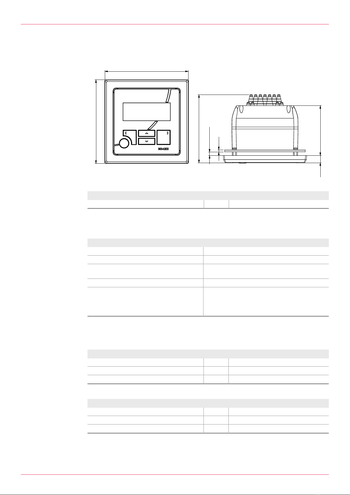
3.1 Dimensional drawing .....................................................5
3.2 Display...........................................................................5
3.3 Connection data ............................................................5
3.3.1 Power supply ....................................................5
3.3.2 Tension spring terminals...................................5
3.3.3 Pulse input and analog input.............................6
3.3.4 Analog output and pulse output ........................6
3.3.5 Modbus interface ..............................................6
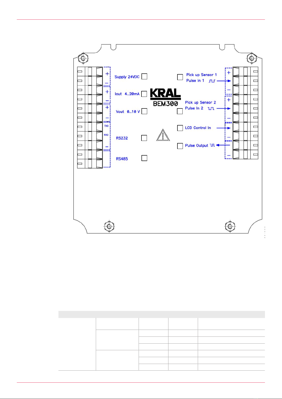
3.4 Connection field.............................................................7
3.5 Pin assignment ..............................................................7
3.6 Ambient conditions ........................................................8
3.7 Accessories ...................................................................8
4 Function description...................................................... 8
4.1 Functional principle........................................................8
4.1.1 Usage................................................................8
4.1.2 Volume measurement.......................................9
4.1.3 Mass calculation ...............................................9
4.1.4 Averaging..........................................................9
4.1.5 Flow direction detection ....................................9
4.1.6 Electronic evaluation.........................................9
4.1.7 Modbus connection...........................................9
4.1.8 Applications.......................................................9
4.2 Modbus interface .........................................................11
5 Transportation, storage............................................... 12
5.1 Scope of delivery .........................................................12
5.2 Unpacking and checking the state of delivery .............12
6 Installation, removal .................................................... 12
6.1 Dangers during installation, removal ...........................12
6.2 Installing the electronic unit in the control cabinet .......12
6.3 Mounting the electronic unit to the wall .......................13
6.4 Mounting the electronic unit at the pipe/flowmeter ......13
7 Connection ................................................................... 14
7.1 Dangers during connection work .................................14
7.2 Connecting cables to the tension spring terminals ......14
7.3 Connecting the pick up ................................................15
7.4 Connecting analog outputs and pulse inputs...............15
7.5 Connecting the power supply ......................................16
8 Commissioning ............................................................ 16
8.1 Checking the electronic unit ........................................16
9 Decommissioning ........................................................ 17
9.1 Taking the electronic unit out of operation...................17
10 Operation........................................................................17
10.1 Abbreviations, units and signals ..................................17
10.1.1 Abbreviations...................................................17
10.1.2 Units ................................................................17
10.1.3 Pulse signals ...................................................17
10.2 Key assignment ...........................................................18
10.3 Operation at a glance...................................................18
11 Menu description...........................................................20
11.1 Start .............................................................................20
11.2 Menu structure .............................................................20
11.3 Menu0: Settings (protected)........................................20
11.4 Menu 1: Display ...........................................................21
11.5 Menu 2: General settings.............................................21
11.6 Menu 3: K-factors flowmeterA.....................................23
11.7 Menu 4: Density table1 ...............................................23
11.8 Menu 7: Alarms............................................................23
12 Maintenance...................................................................24
12.1 Required maintenance.................................................24
12.2 Cleaning the electronic unit..........................................24
13 Disposal..........................................................................24
13.1 Disposing of the electronic unit ....................................24
14 Troubleshooting ............................................................24
14.1 Fault table ....................................................................24
15 Accessories ...................................................................26
15.1 Installation....................................................................26
15.1.1 Fixing kits.........................................................26
15.1.2 Universal mount fixing kit.................................26
15.1.3 Fixing kit for pipe mounting/mounting on OMG
.........................................................................27
15.1.4 Fixing kit mounting on OME ............................27
15.1.5 Adapter set for conversion of BEM4U to
BEM300/BEM500 ........................................27
15.2 Electrical connection ....................................................28
15.2.1 Different voltage ..............................................28
15.2.2 Rack mounting power supply unit EEN12 ......28
15.2.3 Plug-in power supply unit EEN13 ...................30
16 Appendix ........................................................................30
16.1 Glossary.......................................................................30
2OIE 15en-GB Edition 2020-03 Operating instructions

1 About this document
1.1 General information
1 About this document
1.1 General information
These instructions form part of the product and must be kept for future reference. Furthermore please
observe the associated documents.
Notice In these operating instructions the designation "Electronic unit" is used for the "Display and processing
unit".
1.2 Target groups
The instructions are intended for the following persons:
oPersons who work with the product
oOperator-owners who are responsible for the use of the product
Persons who work with the product must be qualified. The qualification ensures that possible dangers
and damage to property that are connected to the activity are detected and avoided. These persons
are qualified personnel who carry out the work properly due to their training, knowledge and experience
and on the basis of the relevant provisions.
Information on the qualification of the personnel is provided separately at the beginning of the indi-
vidual chapters in these instructions. The following table provides an overview.
Target group Activity Qualification
Fitter Mounting,
connection
Qualified personnel for mounting
Electrician Electrical
connection
Qualified personnel for electric installation
Trained personnel Delegated task Personnel trained by the operator-owner who know the
task delegated to them and the possible dangers arising
through improper behaviour.
Tab.1: Target groups
1.3 Associated documents
oDeclaration of conformity according to EU Directive 2014/30/EU
oCorresponding operating instructions of the flowmeter
oCorresponding operating instructions of the sensor
oCalibration certificate
oWork sheet
oWiring diagram
1.4 Symbols
1.4.1 Danger levels
Signal word Danger level Consequences of non-observance
DANGER Immediate threat of danger Serious personal injury, death
WARNING Possible threat of danger Serious personal injury, invalidity
CAUTION Potentially dangerous situation Slight personal injury
ATTENTION Potentially dangerous situation Material damage
Operating instructions OIE 15en-GB Edition 2020-03 3

2 Safety
2.1 Proper use
1.4.2 Danger signs
Meaning Source and possible consequences of non-observance
Electrical voltage Electrical voltage causes serious physical injury or death.
1.4.3 Symbols in this document
Meaning
Warning personal injury
Safety instruction
Request for action
1.
2.
3.
Multi-step instructions for actions
Action result
Cross-reference
2 Safety
2.1 Proper use
oThe electronic unit is provided for usage with a KRAL flowmeter.
oUse the electronic unit only within the operating limits specified in the "Technical data" chapter.
2.2 Foreseeable misuse
oAny use that extends beyond the proper use or any other use is misuse.
2.3 Fundamental safety instructions
The following safety instructions must be observed:
oRead the operating instructions carefully and observe them.
oHave work only carried out by qualified personnel/trained personnel.
oWear personal protective equipment and work carefully.
oObserve the operating instructions of the flowmeter and of the sensors.
4OIE 15en-GB Edition 2020-03 Operating instructions

3 Technical data
3.1 Dimensional drawing
3 Technical data
3.1 Dimensional drawing
145
145
118
86,5
12,5
0,5 - 5,0
4
Fig.1: Dimensional drawing
Parameter Unit Value
H x W x D [mm] 145 x 145 x 118
Tab.2: Dimensions
3.2 Display
Criterion Data
Text display 4lines/20characters
Updating rate 100ms
Background illumination 20levels, can be adjusted via software or analog
input
Contrast 20levels, can be adjusted via software
Language selection oGerman
oEnglish
oFrench
oSpanish
3.3 Connection data
3.3.1 Power supply
Parameter Unit Value
Power supply [VDC] 24±20%
Max. current consumption [mA] 0.5
Insulation voltage [V] <500
3.3.2 Tension spring terminals
Cable type Unit Terminating range
Strand [mm2] 0.08–2.5
Litz wires [mm2] 0.08–2.5
Wire end ferrule [mm2] 0.08–1.5
Operating instructions OIE 15en-GB Edition 2020-03 5

3 Technical data
3.3 Connection data
3.3.3 Pulse input and analog input
Component Designation Unit Value
Pulse input Limit frequency min.-max. [Hz] 0.5–
20000
Power supply for pick up NPN/PNP [VDC] 24
Namur [V] 8.2
Input impedance NPN/PNP [kΩ] 3.2
Namur [kΩ] 1
Can be configured for counter mode or encoder mode
Analog input
0–10V (background
illumination)
Input resistance [kΩ] 3.4
Only possible for U=0V setting in the menu
3.3.4 Analog output and pulse output
Component Designation Unit Value
Analog output
4–20mA
Active current source
Short-circuit proof
Scalable
Load [Ω] <500
Electrical isolation [Veff] 500
Resolution [μA] 1
Temperature drift [%] ±0.1
Calibration tolerance [%] ±0.1
Reaction time: 0.15s x smoothing value
Analog output
0–10V
Active voltage source
Short-circuit proof
Scalable
Load [Ω] >500
Resolution [mV] 1
Temperature drift [%] ±0.1
Calibration tolerance [%] ±0.1
Reaction time: 0.15s x smoothing value
Pulse output Active pulse sources (PNP transistor switches power supply)
Output current max. [mA] 20
Short-circuit proof
Load [kΩ] >1
Scalable
Signal level at 24VDC power supply High [VDC] >20
Low [VDC] <1
Pulse width adjustable High [ms] 2–200
Flow direction detection in the Encoder mode possible
Max. output frequency at pulse width 2ms [Hz] 250
3.3.5 Modbus interface
Designation Unit Data/value
Interface type oRS 232 (SLAVE)
oRS 485 (SLAVE)
Baud rate [Bd] 9600
Data format 8N1 (8 data bits, no parity, 1 stop bit)
Protocol Modbus RTU
Processor cycle time [ms] 20
6OIE 15en-GB Edition 2020-03 Operating instructions

3 Technical data
3.4 Connection field
1
2
3
4
5
6
7
8
9
000766
1
2
3
4567
89
10
11
12 13 14 15 16 17 18 19 20 21
A+
B-
Fig.2: Termination panel electronic unit
1Power supply (24VDC) 6Pick up1
2Analog output (4-20mA) 7Pick up2
3Analog output (0–10V) 8Analog input (0–10V)background illumination
4Serial interface (RS232) 9Pulse output
5Modbus interface (RS485)
The Modbus connection takes place via terminals. The assignment of the terminals is shown in the wir-
ing diagram. The address of the electronic unit at the Modbus can be selected per software, see 2.10
Modbus address.
3.5 Pin assignment
Component Connection/function Terminal
Pick up NPN/PNP
Push-pull
Namur
Pick up1 U+24VDC U+8.2VDC 12
Signal Signal 13
Gnd – 14
Pick up2 (+90°) U+24VDC U+8.2VDC 15
Signal Signal 16
Gnd – 17
Operating instructions OIE 15en-GB Edition 2020-03 7

4 Function description
3.6 Ambient conditions
Component Connection/function Terminal
Analog output 4–20mA 0–10V
Signal 3 5
Gnd 4 6
Pulse output Signal 20
Gnd 21
Analog input Background illumination
0–10V 18
Gnd 19
Serial interface RS485 B 10
A 11
RS232 TxD 7
RxD 8
Gnd 9
Power supply Different power supply units are available as accessories Ä Accessories,Page26.
+24VDC 1
Gnd 2
Tab.3: Pin assignment
3.6 Ambient conditions
Parameter Unit Data/value
Storage temperature min.–max. [°C] -20...+80
Operating temperature min.–max. [°C] -20...+70
Humidity (relative humidity, non-condensing) [%] 97
EMC emitted interference/immunity to interference EN 61326
Vibration oEN60068–2–47
oEN60068–2–64
Shock EN 61373
Isolation min. [V] 500
Degree of protection IP 65
Tab.4: Ambient conditions
3.7 Accessories
Notice The technical data of the accessories are specified separately Ä Accessories,Page26.
4 Function description
4.1 Functional principle
4.1.1 Usage
The electronic unit is provided for usage with a KRAL flowmeter.
Flowmeters generate a specific number of pulses per flow volume unit - depending on the size and
working point. This device-specific characteristic is called the K-factor (unit: pulses/liter) and is spe-
cified on the calibration certificate.
The pulse signals of one flowmeter can be evaluated. A pulse input for pick up with the following func-
tions is available:
oNPN
oPNP
oNamur
8OIE 15en-GB Edition 2020-03 Operating instructions

4 Function description
4.1 Functional principle
Either NPN or PNP can be selected for push-pull pick ups. In addition the flowmeter can also be
equipped with pick ups for flow direction detection. The electronic unit is supplied with settings in ac-
cordance with the customer requirements.
4.1.2 Volume measurement
Each positive edge of the pulse signal starts a period measurement and at the same time stops the
previous measurement. The flow rate is then calculated via the frequency (= inverse of the period dura-
tion) and the K-factor. The inverse of the K-factor is the pulse value in I/P. This is retroactively added to
the total sums for each positive edge of the signal.
4.1.3 Mass calculation
The volume can be converted into mass via a configurable fixed density value (menu4).
4.1.4 Averaging
A strongly fluctuating flow rate causes a jumping display or as a result a fluctuating analog output. The
averaging function reduces this effect by generating a averaging across several measured values. The
number of measured values for averaging can be set. See 2.07Averaging analog output and see
2.12Averaging display rate.
4.1.5 Flow direction detection
In extreme cases the flow direction can change through pulsations, meaning through liquid waves in
the pipe system. Through the use of two pick ups that supply signals out of phase by 90° (square wave
encoder signals), a reversal in the flow direction is recognized by means of the flow direction sensor
and taken into account when calculating the total value. The electronic unit offers incremental encoding
inputs for each flowmeter. This means that the flow direction can be determined without additional
components and taken into account in the calculation at any time.
4.1.6 Electronic evaluation
The electronic unit receives signals from the pick ups and calculates the measured values which are in-
dicated in the display unit and which can be called up at the analog output or at the Modbus interface.
Possibilities of the electronic unit:
oLanguage selection
oDisplay of the measured values in different units (volumes, masses and temperatures)
oAveraged display values
oA density for conversion to mass
oInformation message at faults or invalid inputs
o1 scalable and assignable analog output 0-10V or 4-20mA
o1 scalable and assignable pulse output
o1 analog input 0–10V for background illumination
4.1.7 Modbus connection
The electronic unit can be connected to the system by means of a Modbus interface and can thus be
integrated into existing systems. This ensures simple, reliable and rapid data exchange.
4.1.8 Applications
Different extension stages of the electronic unit are presented on the basis of the following examples.
This allows the required functional scope to be selected in accordance with the requirements.
Single-line measurement
Extension stage Components Functions
000135
Basic
o1 flowmeter
o1 pick up
o1 BEM 300 electronic unit
oElectronic evaluation
oVolume measurement
o1 analog output
o1 pulse output
Operating instructions OIE 15en-GB Edition 2020-03 9

4 Function description
4.1 Functional principle
Extension stage Components Functions
000136
Basic + temperature compensation
o1 flowmeter
o1 pick up
o1 temperature sensor Pt100
o1 BEM500 electronic unit
oElectronic evaluation
oVolume measurement
oMass flow measurement
oTemperature compensation
o2 relay outputs
o2 analog outputs
o2 pulse outputs
oFilling
000137
Basic + flow direction detection
o1 flowmeter
o2 pick ups
o1 BEM 300 electronic unit
oElectronic evaluation
oVolume measurement
oFlow direction detection
o1 analog output
o1 pulse output
000138
Basic + flow direction detection +
temperature compensation
o1 flowmeter
o2 pick ups
o1 temperature sensor Pt100
o1 BEM 500 electronic unit
oElectronic evaluation
oVolume measurement
oFlow direction detection
oMass flow measurement
oTemperature compensation
o2 relay outputs
o2 analog outputs
o2 pulse outputs
oFilling
Tab.5: Extension stages single-line measurement
Notice The BEM 500 electronic unit can also be used for two separate single-line measurements.
Differential measurement
Extension stage Components Functions
000139
Basic
o2 flowmeters
o1 pick up each
o1 BEM500 electronic unit
oElectronic evaluation
oDifferential measurement
o2 relay outputs
o2 analog outputs
o2 pulse outputs
000140
Basic + temperature compensation
o2 flowmeters
o1 pick up each
o1 temperature sensor Pt100
each
o1 BEM500 electronic unit
oElectronic evaluation
oDifferential measurement
oMass flow measurement
oTemperature compensation
o2 relay outputs
o2 analog outputs
o2 pulse outputs
000141
Basic + flow direction detection
o2 flowmeters
o2 pick up each
o1 BEM500 electronic unit
oElectronic evaluation
oDifferential measurement
oFlow direction detection
o2 relay outputs
o2 analog outputs
o2 pulse outputs
10 OIE 15en-GB Edition 2020-03 Operating instructions

4 Function description
4.2 Modbus interface
Extension stage Components Functions
000142
Basic + flow direction detection +
temperature compensation
o2 flowmeters
o2 pick up each
o1 temperature sensor Pt100
each
o1 BEM500 electronic unit
oElectronic evaluation
oDifferential measurement
oFlow direction detection
oMass flow measurement
oTemperature compensation
o2 relay outputs
o2 analog outputs
o2 pulse outputs
Tab.6: Extension stages differential measurement
4.2 Modbus interface
Menu item
Variable
designation
Data
address
(HEX)
No. of
words
Raw data
(decimal)
Decimal
places
Explanation
of data
value
Data
reading
command
to BEM
(HEX)
1.01 QA rate 4006 2 +/-2 147 483 647 1...3 Unit rate 0103 4006 0002 31CA
1.02 Total A1 4100 2 +/-2 000 000 000 1...3 Unit total 0103 4100 0002 D037
Total A2 4102 2 +/-2 000 000 000 1...3 Unit total 0103 4102 0002 71F7
1.04 Serial number 4012 2 0...999 999 0 – 0103 4012 0002 71CE
Software 4020 1 0...65 535 3 – 0103 4020 0001 9000
Hardware 410A 1 0...65 535 3 – 0103 410A 0001 B034
Tab.7: Modbus variables
Data value Value Meaning Value Meaning Value Meaning
Unit rate 1 l/sec 9 lb/sec 17 galUK/h
2 l/min 10 lb/min 18 m³/min
3 l/h 11 lb/h 19 m³/h
4 kg/sec 12 galUS/sec 20 g/sec
5 kg/min 13 galUS/min 21 g/min
6 kg/h 14 galUS/h 22 ml/sec
7 t/min 15 galUK/sec 23 ml/min
8 t/h 16 galUK/min
Unit total 1 l 4 lb 7 m³
2 kg 5 galUS 8 g
3 t 6 galUK 9 ml
No. of decimal
places
1 1decimal place, this means all values with 1...3decimal places must be
divided by 10 (101) to get the actual value.
2 2decimal places, this means all values with 1...3decimal places must be
divided by 100 (102) to get the actual value.
3 3decimal places, this means all values with 1...3decimal places must be
divided by 1000 (103) to get the actual value.
Tab.8: Data values
Example for Total TA1 Data reading command to BEM (query): 0103 4100 0002 D037
Response from BEM: 0103 0400 0160 9E02 5B
Value Meaning
0103 0400 0160 9E... 01=Modbus device address1
0103 0400 0160 9E... 03=Read holding registers function
Operating instructions OIE 15en-GB Edition 2020-03 11

5 Transportation, storage
5.1 Scope of delivery
Value Meaning
0103 0400 0160 9E... 04=Response of BEM consists of 4 bytes:
00 0160 9E 1. Data byte 0 * 228 + 0 * 224 = 0
00 0160 9E 2. Data byte 0 * 220 + 1 * 216 = 65536
00 0160 9E 3. Data byte 6 * 212 + 0 * 28 = 24576
00 0160 9E 4. Data byte 9 * 24 + 14 * 20 = 158
The Modbus value therefore corresponds to the sum 90270
If the value of a data query of the data address is 4186 = 2 (see Tab. Data values number of decimal
places), the Modbus value has to be divided by 100. The result is then 902.7.
If the value of a data query of the data address is 4015 = 5 (see Tab. Data values unit total). The unit is
Total galUS.
The end result for TotalTA1 is therefore 902.7 galUS.
Notice The numbering of the register addresses starts at1, the data addressing at0. This is how e.g. when
reading register1 the data address0 is used.
Notice All units and the number of decimal places should be read out at least during initialization of the elec-
tronic unit, i.e. during switch-on, because these values can be modified manually.
Notice For parameter settings of the electronic unit via Modbus function 10(hex)=write holding registers (pre-
set multiple registers) can be used. Data exchange via the Modbus connection is not password-protec-
ted – avoid unintended overwriting of the total values or parameter addresses!
Notice All data can be read out or written in packages of up to 64words.
Reset of the total values via the Modbus:
oReset command TotalT1: 0110 4100 0002 0400 0000 00CF FC
oReset command TotalT2: 0110 4102 0002 0400 0000 004E 25
5 Transportation, storage
5.1 Scope of delivery
The following components belong to the scope of delivery of the electronic unit:
oOperating instructions
oPassword
oWork sheet
oMounting frame with screws and wedge lock washers
oTerminal tool
oKRAL tool set
5.2 Unpacking and checking the state of delivery
Personnel qualification: oTrained personnel
1. Upon delivery check the product for damage during transportation.
2. Report damage during transportation immediately to the manufacturer.
3. Dispose of packing material in accordance with the locally applicable regulations.
6 Installation, removal
6.1 Dangers during installation, removal
The following safety instructions must be strictly observed:
oHave all work only carried out by electricians.
oDo not take apart the electronic unit.
6.2 Installing the electronic unit in the control cabinet
Personnel qualification: oElectrician
Personal protective equipment: oWork clothing
Aids: oKRAL tool set
12 OIE 15en-GB Edition 2020-03 Operating instructions

6 Installation, removal
6.3 Mounting the electronic unit to the wall
Notice When the space is limited, mounting is also possible without a housing cover and without a seal with
cable entries.
1
2
3
4
5
6
117
117
3
117
117
1Electronic unit
2Front frame
3Control cabinet (section)
4Sealing frame
5Seal with cable entries
6Housing cover
Requirement:
üControl cabinet with plate thickness 0.5-5.0mm
üMounting depth min. 80mm
1. Create a control cabinet section.
2. If the space is limited, remove the housing cover6 and seal with cable entries5.
3. Slide the front frame2 from behind onto the electronic unit1.
4. Place the electronic unit with the front frame from the front into the control cabinet section.
5. Slide the sealing frame 4 from behind onto the electronic unit. In the process the sealing surface
must point to the front.
6. Fasten the front frame2 and sealing frame4 using the 4 supplied screws and wedge lock wash-
ers. Carefully tighten with 1Nm torque.
ðThe electronic unit is ready for the connection of the cables.
6.3 Mounting the electronic unit to the wall
Personnel qualification: oElectrician
Personal protective equipment: oWork clothing
Aids: oKRAL tool set
For wall mounting a universal mount is available as an accessory Ä Accessories,Page26.
2
1
1Electronic unit
2Universal mount
Requirement:
üUniversal mount mounted to the wall
üAll cables have been shortened and connected
1. Slide the electronic unit1 into the universal mount2.
2. Fasten the electronic unit using the supplied screws, washers and wedge lock washers.
ðThe electronic unit is ready to operate after the power supply has been switched on.
6.4 Mounting the electronic unit at the pipe/flowmeter
Personnel qualification: oElectrician
Personal protective equipment: oWork clothing
Aids: oKRAL tool set
Operating instructions OIE 15en-GB Edition 2020-03 13

7 Connection
7.1 Dangers during connection work
The electronic unit can be mounted to the pipe or on the flowmeter by means of the universal mount
and the corresponding fixing kit. The required fixing kit is available as an accessory. Ä Accessor-
ies,Page26
1
2
3
1
2
4
1Electronic unit
2Universal mount
3Fixing kit for mounting at pipe (for flowmeter OMG)
4Fixing kit for flowmeter (for flowmeter OME)
Requirement:
üAll cables have been shortened and connected
1. Mount the universal mount2 on the fixing kit3 or4.
2. Mount the fixing kit including universal mount to the pipe or flowmeter.
3. Slide the electronic unit into the universal mount.
4. Fasten the electronic unit using the supplied screws, washers and wedge lock washers.
ðThe electronic unit is ready to operate after the power supply has been switched on.
7 Connection
7.1 Dangers during connection work
The following safety instructions must be strictly observed:
oHave all work only carried out by electricians.
oThe connecting lines of the sensor connections are to be shielded and laid separately from the
supply and measuring lines.
oEnsure that the power supply is correct (24VDC).
7.2 Connecting cables to the tension spring terminals
Personnel qualification: oElectrician
Personal protective equipment: oWork clothing
Aids: oKRAL tool set
oDiagonal cutter
Requirement:
üCable shortened to correct length
üAll wires stripped to approx. 5mm
12
3
4
35
1. Remove the rear device cover1 and remove the terminal tool2.
14 OIE 15en-GB Edition 2020-03 Operating instructions

7 Connection
7.3 Connecting the pick up
2. Use the diagonal cutter4 to adapt the cable entry3 to the cable diameter.
3. Pull the cable5 through the cable entry3.
6
2 2
7
1
4. Hook the short arbour of the terminal tool2 into the tension spring terminal6 and press away
from the cable opening so that the cable opening opens.
5. Insert the wire7 into the cable opening and remove the terminal tool2.
6. Repeat Steps4 and5 for all the wires.
7. Replace the rear device cover1.
7.3 Connecting the pick up
Personnel qualification: oElectrician
Personal protective equipment: oWork clothing
Aids: oKRAL tool set
oDiagonal cutter
oWiring diagram
ATTENTION
Device damage through incorrect connection
► Observe pin assignment and connection data of the electronic unit Ä Technical data,Page5.
► Before connecting the electronic unit to the power supply, ensure that all consumers (sensors) are
connected correctly. See the wiring plan.
Requirement:
üPick up for flowmeter installed
1. Remove the rear device cover.
2. Use the diagonal cutter to adapt the cable entry to the cable diameter.
3. Pull the cables of the pick ups individually through the cable entries.
4. Connect the cables for pick ups of flowmeterA in accordance with the wiring diagram on the
electronic unit.
5. Replace the rear device cover.
7.4 Connecting analog outputs and pulse inputs
Personnel qualification: oElectrician
Personal protective equipment: oWork clothing
Aids: oKRAL tool set
oDiagonal cutter
oWiring diagram
Operating instructions OIE 15en-GB Edition 2020-03 15

8 Commissioning
7.5 Connecting the power supply
ATTENTION
Device damage through incorrect connection.
► Observe pin assignment and connection data of the electronic unit Ä Technical data,Page5.
► Do not supply voltage to the analog outputs or pulse outputs (active outputs!).
1. Remove the rear device cover.
2. Use the diagonal cutter to adapt the cable entry to the cable diameter.
3. Pull the cables for the analog outputs or pulse outputs individually through the cable entries.
4. Connect the cables for the analog outputs or pulse outputs in accordance with the terminal dia-
gram.
5. Route the cable for analog outputs or pulse outputs to the load and connect the load.
6. Replace the rear device cover.
7.5 Connecting the power supply
Personnel qualification: oElectrician
Personal protective equipment: oWork clothing
Aids: oKRAL tool set
oDiagonal cutter
oWiring diagram
ATTENTION
Device damage through incorrect connection
► Observe pin assignment and connection data of the electronic unit Ä Technical data,Page5.
► Before connecting the electronic unit to the power supply, ensure that all consumers (sensors) are
connected correctly. See the wiring plan.
Requirement:
üAll sensors correctly connected
üSystem in a deenergized state and secured against being switched on
1. Remove the rear device cover.
2. Use the diagonal cutter to adapt the cable entry to the cable diameter.
3. Pull the supply cable (24VDC) through the cable entry and connect.
4. Replace the rear device cover.
5. Connect the supply cable (24VDC) to the power supply of the system.
ðThe electronic unit is ready to operate.
8 Commissioning
8.1 Checking the electronic unit
Some basic checks must be performed before commissioning the electronic unit:
Test Procedure
Installation 1. Check that the electronic unit is seated firmly.
2. In case of wall mounting/pipe mounting or mounting on flowmeter:
Ensure that the rear device cover and cable entries seal properly.
Electrical installation 1. Ensure that the system is deenergized.
2. Remove the rear device cover.
3. Check that the wiring of the power supply at the termination panel is
firm.
4. Check the connection of the power supply to the system.
5. Check the numbering of the pick ups.
6. Check the assignment of the pick ups.
7. Check the pick up connections, see wiring diagram.
16 OIE 15en-GB Edition 2020-03 Operating instructions

9 Decommissioning
9.1 Taking the electronic unit out of operation
Test Procedure
Function test Electronic unit:
Switch on the power supply.
ðThe start message is displayed on the display unit.
ðThe following is displayed no later than 3 seconds:
1.01 Display Volumeter A.
9 Decommissioning
9.1 Taking the electronic unit out of operation
DANGER
Risk of death resulting from electric shock.
► The electronic unit may only be separated from the power supply by an authorized electrician.
Switch off the power supply of the system.
Notice All the settings and total values are retained when the electronic unit is switched off or the power sup-
ply fails. After recommissioning, instantaneous values (Q, T) can be recalculated.
10 Operation
10.1 Abbreviations, units and signals
10.1.1 Abbreviations
Abbreviation Meaning
Qnom Nominal flow rate
QA Current flow flowmeterA
∑A1 Total flow flowmeterA since last reset (without password protection)
∑A2 Total flow flowmeterA since last reset (with password protection)
Rho Density
f Frequency
K K-factor
10.1.2 Units
In order to make extensive conversions by the user superfluous, various country-specific units and
quantities of a unit are available for the display.
Abbreviations Meaning
Volume ml, l, galUS, galUK, m3
Masses g, kg, t, lb
Flow, volumetric ml/s, ml/min, l/s, l/min, l/h, galUS/s, galUS/min, galUS/h, galUK/s, galUK/min,
galUK/h, m3/min, m3/h
Flow, mass-specific g/s, g/min, kg/s, kg/min, kg/h, t/min, t/h, lb/s, lb/min, lb/h
Density kg/m3, lb/galUS, lb/galUK
Frequency Hz
K-factor P/l
10.1.3 Pulse signals
A pulse input for pick up with the following functions is available:
oNPN
oPNP
oNamur
Either NPN or PNP can be selected for push-pull pick ups, see 2.11 Setting Function Pick up.
Operating instructions OIE 15en-GB Edition 2020-03 17

10 Operation
10.2 Key assignment
10.2 Key assignment
The electronic unit is operated by means of five keys.
Button Function
oConfirm the entry
oReset the total values
oConfirm the selection
oSwitch to the following menu item
oSelect the previous unit
oIncrease the digit
oSwitch to the previous menu item
oSelect the next unit
oDecrease the digit
Navigate one menu higher
Navigate one menu lower
Menu items can be called up via key combinations.
Key combination Function
+ 1.12Help operation
+ 1.07Setting select language
+ Menu7: Alarms
+ 1.01Display VolumeterA
10.3 Operation at a glance
General operating steps
The following table describes the entry of the password as well as general operating steps, such as the
changing of values and units. The password is included in the scope of delivery and consists of four di-
gits.
Aim Operating steps
Enter the password,
see 2.01Setting
Enable Password
Deactivate password protection
1. Press .
ðThe password prompt is displayed.
ðFlashing cursor indicates the active input field.
2. With or change the position within the number input.
3. With or increase or decrease the digits.
4. Repeat Steps2 and3 for all the digits.
5. Press .
ðPassword protection is deactivated: The text No is displayed. Change of
settings possible. Password protection is reactivated automatically after
approx. 30 minutes.
Activate password protection
1. Press .
2. With or select Yes .
3. Press .
18 OIE 15en-GB Edition 2020-03 Operating instructions

10 Operation
10.3 Operation at a glance
Aim Operating steps
Change the value Requirement:
2.01Setting Enable Password Set to No .
1. Press .
ðFlashing cursor indicates the active input field.
2. With or change the position within the number input.
3. With or increase or decrease the digits.
4. Repeat Steps2 and3 for all the digits.
5. Press .
Change the unit Requirement:
2.01 Setting Enable Password Set to No .
1. Press .
ðFlashing cursor indicates the active input field.
2. Select with or .
3. Press .
Operating the basic functions
The following table describes the basic operating steps. They can be carried out in part without a pass-
word having to be entered.
Aim Operating steps
Read the load, see
1.01Display
VolumeterA
Call up menu item
Press + simultaneously.
Reset sum, see
1.02 Display
Volumeter A Total
Reset of the total values
1. Press .
ðTotal value 1 is selected.
2. Press for three seconds.
ðTotal value1 is reset.
3. Press .
ðTotal value2 is selected.
4. Press for three seconds.
ðEntry of password required.
5. Enter password and press .
ðTotal value2 is reset.
Select the lan-
guage, see
1.07Setting
language selection
Call up menu item
Press + simultaneously.
Select the language
1. Press .
ðFlashing cursor indicates the active input field.
2. With or select the language.
3. Press .
ðThe selected language is applied after a different menu item has been called
up.
Operating instructions OIE 15en-GB Edition 2020-03 19

11 Menu description
11.1 Start
Aim Operating steps
Call up help, see
1.12 Help
operation
Call up menu item
Press + simultaneously.
Navigate
1. Browse with or .
2. Press to exit the help.
11 Menu description
11.1 Start
Menu item Description
1.04Information = Start message with display of the serial number as well as version of the software and hardware.
After switching on the start message shows for three seconds that the electronic unit is ready to oper-
ate. After that the following is displayed 1.01Display Volumeter A
Note:
Activate or deactivate the start message, see 2.09Setting Display Start Message .
11.2 Menu structure
Menu Information
0 Settings (protected) o...
o0.09Pulse output pulse width setting
o...
1 Display o1.01Display Volumeter A
o1.02Display VolumeterA Total
o1.03Display Reset Group Error Message
o1.04Information
o1.05Setting Display Brightness
o1.06Setting Display Contrast
o1.07Setting select language
o1.12Help operation
o1.13Enter Password
2 Settings o2.01Setting Enable Password
o2.02Setting Select Unit Rate
o2.03Setting Select Unit Total
o2.04Setting Select Unit Density
o2.05Setting Function Analog Output
o2.06Setting Scale Analog Output1
o2.07Setting Averaging Analog Average
o2.08Setting Scale Pulse Output1
o2.09Setting Display Start Message
o2.10Setting Address Modbus
o2.11Setting Function Pick up
3 K-factors flowmeterA o3.01K-factor VolumeterA Point1
4 Density table1 o4.01Density table Point1
7 Alarms o7.01No alarm. The electronic unit works without problems.
o7.07Alarm 6 maximum flow is exceeded. Check the volumeter!
o...
o7.19Alarm 18 unit changed Correct the scale of pulse output!
11.3 Menu0: Settings (protected)
oProtected area (access only with system password)
oShould only be used by the user to the set the pulse width
o Ä Operation,Page17
20 OIE 15en-GB Edition 2020-03 Operating instructions
Table of contents
Other KRAL Measuring Instrument manuals

KRAL
KRAL OMS Series User manual

KRAL
KRAL OME Series User manual

KRAL
KRAL BEM 200 User manual

KRAL
KRAL Volumeter OMG Series User manual

KRAL
KRAL OMP Series User manual

KRAL
KRAL OMH Series User manual

KRAL
KRAL OMS Series User manual

KRAL
KRAL BEM 150 User manual

KRAL
KRAL OMG Series User manual

KRAL
KRAL Volumeter OMG 13 User manual