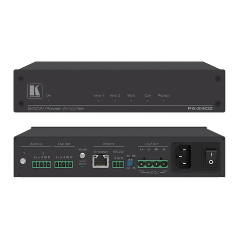
Kramer VP-200K User manual

Kramer Electronics, Ltd.
USER MANUAL
Models:
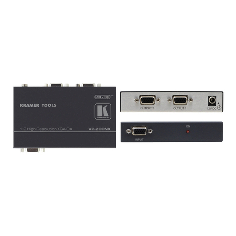
VP-200K, 1:2 High Resolution UXGA DA
VP-300K, 1:3 High Resolution UXGA DA
VP-400K, 1:4 High Resolution UXGA DA

Contents
i
Contents
1Introduction 1
2Getting Started 1
2.1 Quick Start 2
3Overview 3
3.1 DDC Support 3
3.2 Defining EDID 3
3.3 Recommendations for Best Performance 4
4Your High Resolution XGA DA 4
4.1 Your VP-200K 1:2 High Resolution UXGA DA 5
4.2 Your VP-300K 1:3 High Resolution UXGA DA 6
4.3 Your VP-400K 1:4 High Resolution UXGA DA 7
5Connecting the VP-300K 1:3 High Resolution UXGA DA 8
6Technical Specifications 10
Figures
Figure 1: VP-200K 1:2 High Resolution UXGA DA 5
Figure 2: VP-300K 1:3 High Resolution UXGA DA 6
Figure 3: VP-400K 1:4 High Resolution UXGA DA 7
Figure 4: Connecting the VP-300K 1:3 High Resolution UXGA DA 9
Tables
Table 1: VP-200K 1:2 High Resolution UXGA DA Features 5
Table 2: VP-300K 1:3 High Resolution UXGA DA Features 6
Table 3: VP-400K 1:4 High Resolution UXGA DA Features 7
Table 4: Technical Specifications of the High Resolution UXGA DA 10

Introduction
1
1 Introduction
Welcome to Kramer Electronics! Since 1981, Kramer Electronics has been
providing a world of unique, creative, and affordable solutions to the vast
range of problems that confront the video, audio, presentation, and
broadcasting professional on a daily basis. In recent years, we have
redesigned and upgraded most of our line, making the best even better! Our
1,000-plus different models now appear in 11 groups1
Congratulations on purchasing your Kramer TOOLS VP-200K1:2 High
Resolution UXGA DA and/or VP-300K1:3 High Resolution UXGA DA
and/or VP-400K1:4 High Resolution UXGA DA, which are ideal for:
that are clearly
defined by function.
•Dual monitor systems, stores, and points of sale
•Presentation systems
The package includes the following items:
•VP-200K 1:2 High Resolution UXGA DA and/or VP-300K 1:3
High Resolution UXGA DA and/or VP-400K 1:4 High Resolution
UXGA DA
•One 3' VGA Male/Male Cable2
•Power adapter (5V DC Input) and this user manual
3
2 Getting Started
We recommend that you:
•Unpack the equipment carefully and save the original box and
packaging materials for possible future shipment
•Review the contents of this user manual
•Use Kramer high performance high resolution cables4
1 GROUP 1: Distribution Amplifiers; GROUP 2: Switchers and Matrix Switchers; GROUP 3: Control Systems;
GROUP 4: Format/Standards Converters; GROUP 5: Range Extenders and Repeaters; GROUP 6: Specialty AV Products;
GROUP 7: Scan Converters and Scalers; GROUP 8: Cables and Connectors; GROUP 9: Room Connectivity;
GROUP 10: Accessories and Rack Adapters; GROUP 11: Sierra Products
2 Model name: C-GM/GM-3
3 Download up-to-date Kramer user manuals from the Internet at this URL: http://www.kramerelectronics.com
4 The complete list of Kramer cables is on our Web site at http://www.kramerelectronics.com

KRAMER: SIMPLE CREATIVE TECHNOLOGY
Getting Started
2
2.1 Quick Start
This quick start chart summarizes the basic setup and operation steps1.
1 This quick start also applies to the VP-200K, which has two outputs, and the VP-400K, which has four outputs

Overview
3
3 Overview
The Kramer TOOLS VP-200K,VP-300Kand VP-400Kare 1:2, 1:3 and 1:4
(respectively) distribution amplifiers for UXGA and higher resolution signals.
The VP-200K,VP-300Kand VP-400Kaccept one input, provide correct
buffering and isolation, and then distribute the signal to two, three or four
(respectively) identical outputs on high-density 15-pin HD connectors.
In particular, the High Resolution UXGA DA:
•Has a high video bandwidth exceeding 400MHz, ensuring that it
remains transparent even at high-resolution graphics modes such
as UXGA (1600x1200)
•Supports DDC (Display Data Channel) communication between
the input and output 1 high-density 15-pin HD connectors on pins
11, 12 and 15
•Supports EDID PassThru that passes EDID signals from source to
display
•Includes the Kramer innovative integrated sync processing;
KR-ISP™ technology, which lets you achieve a sharp, stable
image when the sync level is too low, by restoring the sync signal
waveform
•Includes an ID Bit control switch as well as polarity switches
•Is 5V DC fed and is housed in a DigiTOOLS®enclosure
3.1 DDC Support
When establishing a VGA connection between a PC or laptop and a display
device, a set of parameters known as EDID is exchanged between them,
which is carried over the DDC channel. In some PC graphic cards and
laptops, this information exchange is essential for proper VGA OUT
operation.
3.2 Defining EDID
The Extended Display Identification Data (EDID1
1 Defined by a standard published by the Video Electronics Standards Association (VESA)
) is a data-structure,
provided by a display, to describe its capabilities to a graphics card (that is
connected to the display’s source). The EDID enables the PC or laptop to
“know” what kind of monitor is connected to the output. The EDID
includes the manufacturer’s name, the product type, the timing data
supported by the display, the display size, luminance data and (for digital
displays only) the pixel mapping data.

KRAMER: SIMPLE CREATIVE TECHNOLOGY
Your High Resolution XGA DA
4
3.3 Recommendations for Best Performance
Achieving the best performance means:
•Connecting only good quality connection cables, thus avoiding
interference, deterioration in signal quality due to poor matching,
and elevated noise levels (often associated with low quality
cables)
•Avoiding interference from neighboring electrical appliances and
positioning your VP-200K,VP-300Kand VP-400Kaway from
moisture, excessive sunlight and dust
4 Your High Resolution XGA DA
This section defines the:
•VP-200K1:2 High Resolution UXGA DA (see section 4.1)
•VP-300K1:3 High Resolution UXGA DA (see section 4.2)
•VP-200K1:4 High Resolution UXGA DA (see section 4.3)

Your High Resolution XGA DA
5
4.1 Your VP-200K 1:2 High Resolution UXGA DA
Figure 1 and Table 1 define the VP-200K:
Figure 1: VP-200K 1:2 High Resolution UXGA DA
Table 1: VP-200K 1:2 High Resolution UXGA DA Features
#
Feature
Function
1 5V DC +5V DC connector for powering the unit
2 ID Bit Switch Slide down to set to ON1; up to set to OFF2
3
Vs (Vertical Sync) Switch Set both switches
3
to Hi-Z (TTL
4
4
) if the source is,
for example, a digital graphics card. Set both
switches to 75Ω(ANALOG) if the source is analog
based, for example, an RGBHV source with coaxial
cable for sync
Hs (Horizontal Sync) Switch
5 OUTPUT 1 15-pin HD Connector Connect to the computer graphics acceptor 1
6 OUTPUT 2 15-pin HD Connector Connect to the computer graphics acceptor 2
7 INPUT 15-pin HD Connector Connect to the computer graphics source
8 ON LED Illuminates when receiving power
1 Enabling the notebook or laptop to output a VGA signal to an external VGA monitor
2 When the source is not a laptop (for example, a PC)
3 Both the Hs and the Vs switches MUST be set identically (no harm will occur to the graphics source if the switches are set
to the wrong direction)
4 “Transistor-Transistor Logic” is a term used in digital electronics describing the ability of a device or circuit to be connected
directly to the input or output of digital equipment. Such compatibility eliminates the need for interfacing circuitry

KRAMER: SIMPLE CREATIVE TECHNOLOGY
Your High Resolution XGA DA
6
4.2 Your VP-300K 1:3 High Resolution UXGA DA
Figure 2 and Table 2 define the VP-300K:
Figure 2: VP-300K 1:3 High Resolution UXGA DA
Table 2: VP-300K 1:3 High Resolution UXGA DA Features
#
Feature
Function
1 5V DC +5V DC connector for powering the unit
2 ID Bit Switch Slide down to set to ON
1
; up to set to OFF
2
3
Vs (Vertical Sync) Switch Set both switches
3
to Hi-Z (TTL
4
4
) if the source is, for
example, a digital graphics card. Set both switches to 75Ω
(ANALOG) if the source is analog based, for example, an
RGBHV source with coaxial cable for sync
Hs (Horizontal Sync) Switch
5 OUTPUT 1 15-pin HD Connector Connect to the computer graphics acceptor 1
6 OUTPUT 2 15-pin HD Connector Connect to the computer graphics acceptor 2
7 INPUT 15-pin HD Connector Connect to the computer graphics source
8 OUTPUT 3 15-pin HD Connector Connect to the computer graphics acceptor 3
9 ON LED Illuminates when receiving power
1 Enabling the notebook or laptop to output a VGA signal to an external VGA monitor
2 When the source is not a laptop (for example, a PC)
3 Both the Hs and the Vs switches MUST be set identically (no harm will occur to the graphics source if the switches are set
to the wrong direction)
4 “Transistor-Transistor Logic” is a term used in digital electronics describing the ability of a device or circuit to be connected
directly to the input or output of digital equipment. Such compatibility eliminates the need for interfacing circuitry

Your High Resolution XGA DA
7
4.3 Your VP-400K 1:4 High Resolution UXGA DA
Figure 3 and Table 3 define the VP-400K:
Figure 3: VP-400K 1:4 High Resolution UXGA DA
Table 3: VP-400K 1:4 High Resolution UXGA DA Features
#
Feature
Function
1 5V DC +5V DC connector for powering the unit
2 ID Bit Switch Slide down to set to ON1; up to set to OFF2
3
Vs (Vertical Sync) Switch Set both switches
3
to Hi-Z (TTL
4
4
) if the source is, for
example, a digital graphics card. Set both switches to
75Ω(ANALOG) if the source is analog based, for
example, an RGBHV source with coaxial cable for sync
Hs (Horizontal Sync) Switch
5 OUTPUT 1 15-pin HD Connector Connect to the computer graphics acceptor 1
6 OUTPUT 2 15-pin HD Connector Connect to the computer graphics acceptor 2
7 INPUT 15-pin HD Connector Connect to the computer graphics source
8 OUTPUT 3 15-pin HD Connector Connect to the computer graphics acceptor 3
9 ON LED Illuminates when receiving power
10 OUTPUT 4 15-pin HD Connector Connect to the computer graphics acceptor 4
1 Enabling the notebook or laptop to output a VGA signal to an external VGA monitor
2 When the source is not a laptop (for example, a PC)
3 Both the Hs and the Vs switches MUST be set identically (no harm will occur to the graphics source if the switches are set
to the wrong direction)
4 “Transistor-Transistor Logic” is a term used in digital electronics describing the ability of a device or circuit to be connected
directly to the input or output of digital equipment. Such compatibility eliminates the need for interfacing circuitry

KRAMER: SIMPLE CREATIVE TECHNOLOGY
Connecting the VP-300K 1:3 High Resolution UXGA DA
8
5 Connecting the VP-300K 1:3 High Resolution UXGA DA
To connect your VP-300K1:3 High Resolution UXGA DA1, as the example
in Figure 4 illustrates, do the following2
1. Connect a computer graphics source to the INPUT 15-pin HD connector.
:
2. Connect the OUTPUT 15-pin HD connectors to up to three3
Connect the OUTPUT 1 connector to acceptor 1 (for example, a
projector)
acceptors,
as follows:
Connect the OUTPUT 2 connector to acceptor 2 (for example,
an LCD monitor)
Connect the OUTPUT 3 connector to acceptor 3 (for example, a
display)
3. Connect the 5V DC power adapter (wall transformer) to the 5V DC socket
and connect the transformer to the mains electricity.
4. If required, set the:
Hs and Vs switches
ID Bit switch to ON
1 From this section on, all the information is relevant to the VP-200K, VP-300K and VP-400K, unless noted otherwise
2 Switch OFF the power on each device before connecting it to your VP-300K. After powering up your VP-300K, switch on
the power on each device
3 Two for the VP-200K and four for the VP-400K

Connecting the VP-300K 1:3 High Resolution UXGA DA
9
Figure 4: Connecting the VP-300K 1:3 High Resolution UXGA DA

KRAMER: SIMPLE CREATIVE TECHNOLOGY
Technical Specifications
10
6 Technical Specifications
Table 4 includes the technical specifications:
Table 4: Technical Specifications1
of the High Resolution UXGA DA
VP-200K VP-300K VP-400K
INPUT: 1 UXGA on an 15-pin HD connector
OUTPUTS:
2 UXGA on 15-pin HD
connectors
3 UXGA on 15-pin HD
connectors
4 UXGA on 15-pin HD
connectors
MAX. OUTPUT LEVEL: 2.2Vpp
BANDWIDTH (-3dB): 400MHz
DIFF. GAIN: 0.03%
DIFF. PHASE: 0.03 Deg
K-FACTOR: <0.05%
S/N RATIO: 72dB @5MHz
CONTROLS: Internal ID BIT switch; internal analog/TTL switches for setting the sync
COUPLING: DC
POWER SOURCE: 5V DC, 130mA
DIMENSIONS: 12.1cm x 7.18cm x 2.42cm (4.76" x 2.83" x 0.95", W, D, H)
WEIGHT: 0.3kg (0.67lbs) approx.
ACCESSORIES: Power supply, one 3' VGA male/male cable
2
OPTIONS: ,
mounting bracket
RK-3T 19" rack adapter
1 Specifications are subject to change without notice
2 Model name: C-GM/GM-3

11
LIMITED WARRANTY
WHOISPROTECTED?
WHATISCOVEREDANDWHATISNOTCOVERED
WHATWEWILLPAYFORANDWHATWEWILLNOTPAYFOR
HOW YOU CAN GET WARRANTY SERVICE
LIMITATIONOFIMPLIEDWARRANTIES
EXCLUSIONOFDAMAGES
CAUTION!
Kramer Electronics (hereafter ) warrants this product free from defects in material and workmanship under the
following terms. Kramer
HOWLONGISTHE WARRANTY
Labor and parts are warranted for seven years from the date of the first customer purchase.
Only the first purchase customer may enforce this warranty.
Wewillpaylaborandmaterialexpensesforcovereditems.Wewillnotpayforthefollowing:
The liability of Kramer for any effective productsis limited to the repairor replacement of theproduct at our option. Kramer shall
notbeliablefor:
Thiswarrantygivesyouspecificlegalrights,andyoumayalsohaveotherrights,whichvaryfromplacetoplace.
AllproductsreturnedtoKramerforservicemusthavepriorapproval.Thismaybeobtainedfromyourdealer.
Thisequipmenthasbeentestedtodeterminecompliancewiththerequirementsof:
EN-50081: "Electromagneticcompatibility(EMC);
genericemissionstandard.
Residential,commercialandlightindustry"
EN-50082: "Electromagneticcompatibility(EMC)genericimmunitystandard.
Part1:Residential,commercialandlightindustryenvironment".
CFR-47: FCC* Rules and Regulations:
Part 15: “Radio frequency devices
Subpart B Unintentional radiators”
Except as below, this warranty covers all defects in material or workmanship in this product. The following are not covered
bythewarranty:
1. Any product which is not distributed by Kramer, or which is not purchased from an authorized Kramer dealer. If you are
uncertain as to whether a dealer is authorized, please contact Kramer at one of the agents listed in the Web site
www.kramerelectronics.com.
2. Any product, on which the serial number has been defaced, modified or removed, or on which the WARRANTYVOID
TAMPERED sticker has been torn,
3. Damage,deteriorationormalfunctionresultingfrom:
i) Accident,misuse,abuse,neglect,fire, water,lightningorotheractsofnature
ii) Productmodification,orfailuretofollowinstructionssuppliedwiththeproduct
iii) RepairorattemptedrepairbyanyonenotauthorizedbyKramer
iv) Anyshipmentoftheproduct(claimsmustbepresentedtothecarrier)
v) Removalorinstallationoftheproduct
vi) Anyothercause,whichdoesnotrelatetoaproductdefect
vii)Cartons,equipmentenclosures,cablesoraccessoriesusedinconjunctionwiththeproduct
1. Removalorinstallationscharges.
2. Costs of initial technical adjustments (set-up), including adjustment of user controls or programming. These costs are the
responsibilityoftheKramerdealerfromwhomtheproductwaspurchased.
3. Shippingcharges.
1. To obtain service on you product, you must take or ship it prepaid to any authorized Kramerservice center.
2. Whenever warranty service is required, the original dated invoice (or a copy) must be presented as proof of warranty
coverage, and should be included in any shipment of the product. Please also include in any mailing a contact name,
company, address, and a description of the problem(s).
3. For the name of the nearest Kramer authorized service center, consult your authorized dealer.
All implied warranties, including warranties of merchantability and fitness for a particular purpose, arelimited in duration to
the length of this warranty.
1. Damagetootherpropertycausedbydefectsinthisproduct,damagesbaseduponinconvenience,lossofuseoftheproduct,loss
oftime,commercialloss;or:
2. Anyother damages,whetherincidental,consequential or otherwise.Some countries maynotallow limitations onhow long an
implied warranty lasts and/or do not allow the exclusion or limitation of incidental or consequential damages, so the above
limitationsandexclusionsmaynotapplytoyou.
Servicing the machines can only be done by an authorized Kramer technician. Any user who makes changes or
modifications to the unit without the expressed approval of the manufacturer will void user authority to operate the
equipment.
UsethesuppliedDCpowersupplytofeedpowertothemachine.
Pleaseuserecommended interconnection cablestoconnect the machineto other components.
IF reattached, removed or otherwise interfered with.
*FCCandCEapprovedusingSTPcable(fortwistedpairproducts)
NOTE:
Part1:

Kramer Electronics, Ltd.
Web site: www.kramerelectronics.com
P/N: 2900-000385 REV 3
For the latest information on our products and a list of Kramer
distributors, visit our Web site:
www.kramerelectronics.com,
where updates to this user manual may be found.
We welcome your questions, comments and feedback.
Caution
Safety Warning:
Disconnect the unit from the power supply before
opening/servicing.
P/N:
2900- 000385QS
Rev:
3
Other manuals for VP-200K
2
This manual suits for next models
2
Table of contents
Other Kramer Amplifier manuals

Kramer
Kramer VM-4UX User manual

Kramer
Kramer TOOLS VP-210XL User manual

Kramer
Kramer VP-103 User manual

Kramer
Kramer VP-450 User manual

Kramer
Kramer 901 User manual

Kramer
Kramer VP-200AK User manual

Kramer
Kramer VM-114H User manual

Kramer
Kramer VM-30AV User manual

Kramer
Kramer Cobra DA9 User manual

Kramer
Kramer VM-50CA User manual

Kramer
Kramer VP-123 User manual

Kramer
Kramer VM-8DVI-R User manual

Kramer
Kramer PT-101R User manual

Kramer
Kramer VM-20HD User manual

Kramer
Kramer 905xl User manual

Kramer
Kramer VA-4 User manual

Kramer
Kramer TOOLS VM-2C User manual

Kramer
Kramer PT-102A User manual

Kramer
Kramer 123Vxl User manual

Kramer
Kramer VM-22HD User manual