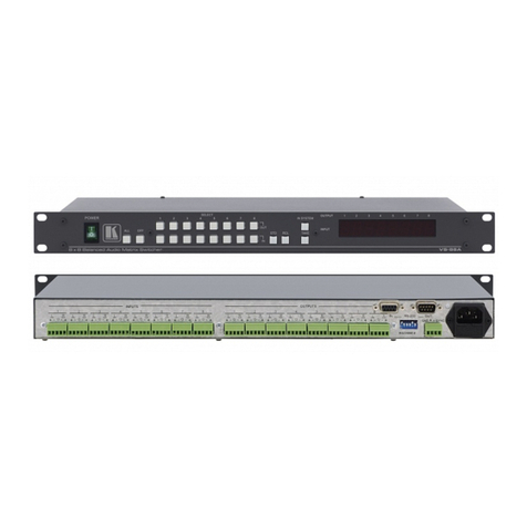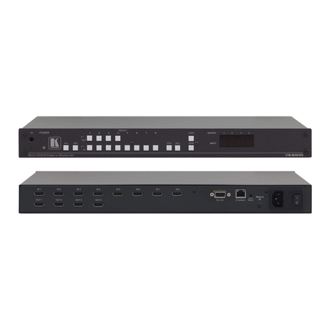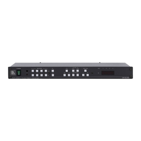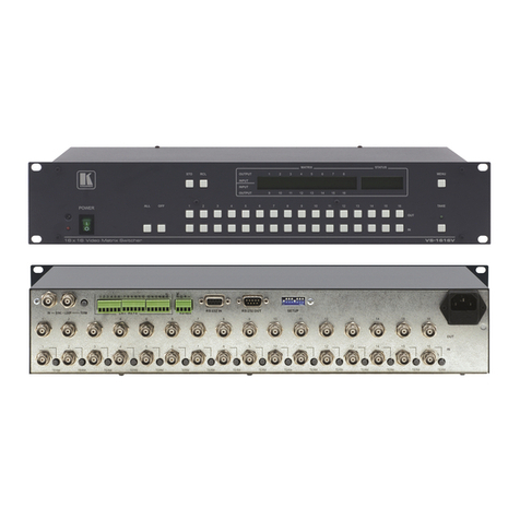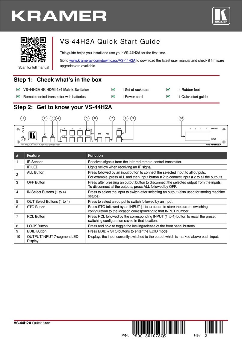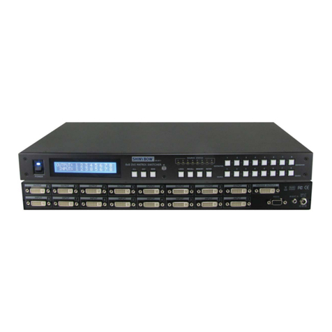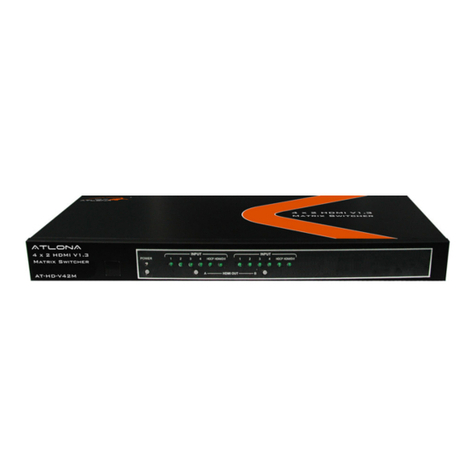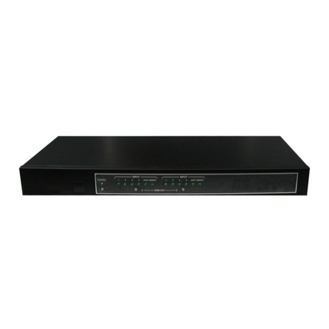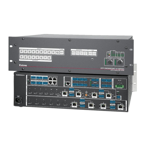
Connect to an HDBT transmitter and/or HDMI source.
Input 1 is user configurable. You can select the active input
connector via web-UI.
Connect to an HDMI source (2-8).
AUDIO OUTPUTS
5-pin Terminal Block
Connectors
Connect to a stereo balanced audio acceptor (1 to 2) to output De-
embedded audio from HDMI Output 1 or Output 2.
Connect to a stereo balanced audio acceptor (A to B) to output De-
embedded audio from any HDMI 3-7 Outputs (default Output 3, or
4).
IR (Rx, Tx) left 2-pins on a
5-pin Terminal Block
Connectors
Connect to the IR connector of an HDBT output (Tx to Rx and Rx to
Tx), to extend IR signal between an HDBT transmitter on the input
and HDBT receiver on an output.
RS-232 (G, Rx, Tx) right 3-pins
on a 5-pin Terminal Block
Connectors
Connect to a serial controller or RS-232 controlled device for RS-
232 signal extension via the HDBT input.
IR (Rx, Tx) left 2-pins on a
5-pin Terminal Block
Connectors
Connect to the IR connector of an HDBT input (Tx to Rx and Rx to
Tx), to extend IR signal between an HDBT receiver on an output
and an HDBT transmitter on an input.
RS-232 (G, Rx, Tx) right 3-pins
on a 5-pin Terminal Block
Connectors
Extend RS-232 signal between the HDBT port and the HDBT
receiver: Connect to serially control a device connected to the
HDBT receiver; or to serially control a local device using a controller
connected to the HDBT receiver.
HDBT/HDMI RJ-45/HDMI
Connectors (1 to 2)
Connect to an HDBT receiver and/or HDMI acceptor (mirrors HDBT
output signal).
Connect to HDMI acceptors.
Connect to an HDMI acceptor. Output 9 mirrors Output 8.
CNTL (Rx, Tx) 2-pin Terminal Block Connector
(GND is common for CNTL and RS-232)
Connect to a PC to control MTX3-88-SE.
RS-232 (G, Rx, Tx) 3-pin Terminal Block Connector
Connect to a serially-controlled device to control the unit via IP
(Default TCP port: 5001).
For configuring the functionality of the IR and RS-232 ports
For more details, refer to the MTX3-88-SE User Manual.
Turn the device on and off.
Mains Power Connector and Fuse
Step 3: Mounting MTX3-88-SE
To rack mount the matrix, attach both
rack ears (by removing the screws from
each side of the matrix and replacing
those screws through the rack ears) or
place the matrix on a table.
•Ensure that the environment (e.g., maximum ambient
temperature & air flow) is compatible for the device.
•Avoid uneven mechanical loading.
•Appropriate consideration of equipment nameplate
ratings should be used for avoiding overloading of the
circuits.
•Reliable earthing of rack-mounted equipment should be
maintained.
