manuals.online logo
Brands
  1. Home
  2. •
  3. Brands
  4. •
  5. Kramer
  6. •
  7. Matrix Switcher
  8. •
  9. Kramer VP-778 User manual

Kramer VP-778 User manual

VP
-778 Quick Start (P/N: 2900-300445QS REV 1)
P/N:
2900- 300445QS
Rev:
1
Scan for full manual
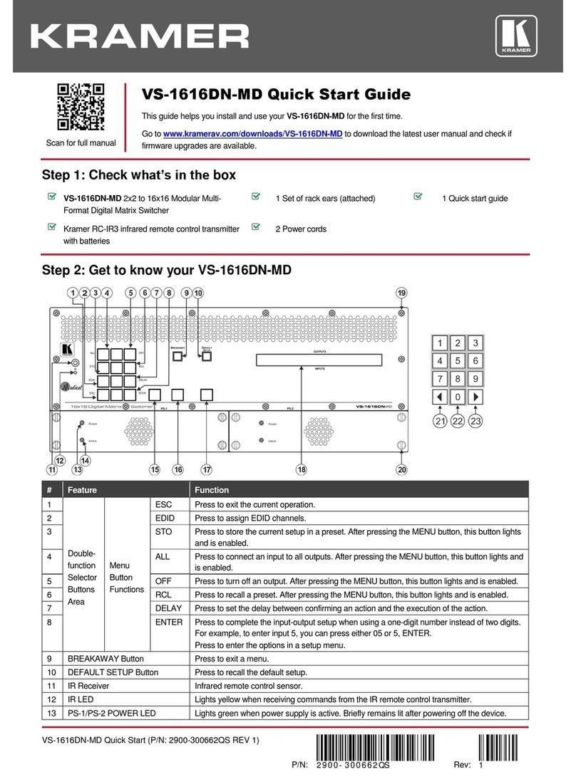
VP-778 Quick Start Guide
This guide helps you install and use your VP-778 for the first time.
Go to www.kramerav.com/downloads/VP-778 to download the latest user manual and check if firmware
upgrades are available.
Step 1: Check what’s in the box
VP-778
Presentation Matrix Switcher/Dual Scaler 1 Set of rack ears 4 Rubber feet
IR remote control transmitter with batteries 1 Power cord 1 Quick start guide
2 DVI (M) to 15-pin HD (F) (AD-DM/GF) 2 DVI-A (M) to 5 BNC (F) adapter cables (ADC-DMA/5BF-1)
Step 2: Get to know your VP-778
# Feature Function
1 IR LED Lights red when the unit accepts IR remote commands
2 IR Receiver Accepts IR remote commands
3
MODE Button
Select the operation mode: audio follow video (AFV), Video or audio
4
Mode LED indicators
Indicate the operation mode, as selected via the MODE button
5 CH 1 INPUT
Selector Buttons HDMI Press to select the HDMI input (from 1 to 4)
DVI-U Press to select the DVI universal input: HDMI, VGA, component or composite video (from 1 to 2)
HDBT
Press to select the HDBT input (from 1 to 2)
6
CH 2 INPUT
Selector Buttons
HDMI
Press to select the HDMI input (from 1 to 4)
DVI-U Press to select the DVI universal input: HDMI, VGA, component or composite video (from 1 to 2)
HDBT Press to select the HDBT input (from 1 to 2)
7
CH 1 FREEZE Button
Press to freeze/unfreeze the CH 1 output video image
8
CH 2 FREEZE Button
Press to freeze/unfreeze the CH 2 output video image
9 CH 1 BLANK Button Press to toggle between a blank screen (black) and the CH 1 display
10 CH 2 BLANK Button Press to toggle between a blank screen (black) and the CH 2 display
11
USR1 User-defined Button
can be assigned and programmed (for example, to turn a projector on and off)
12
USR2 User-defined Button
can be assigned and programmed (for example, to turn a projector on and off)
13 MENU Button Press to access/exit the OSD menu. While browsing the CH1 OSD menu, press and hold the
MENU button to jump to the CH2 menu and vice versa. When in the MIC Effects menu, press and
hold the MENU button to toggle between MIC 1 and MIC 2
# Feature Function
14
Navigation Buttons
Button// VOLUME
Button
Press to move to the previous level in the OSD screen. When not within the OSD menu, press to
decrease the Audio CH1 volume
Button // VOLUME
Button
Press to move to the next level in the OSD screen. When not within the OSD menu, increase the
Audio CH 1 volume
// VOLUME Button Press to move down the menu list and to decrease numerical values. When in the transition mode
and not within the OSD menu mode, press to decrease the Audio CH 2 volume
// VOLUME Button Press to move up the menu list values and to increase numerical values. When in the transition
mode and not within the OSD menu mode, press to increase the Audio CH 2 volume
ENTER Button Press to enter sub-menu items, and save. When in the transition mode and not within the OSD
menu, performs as a TAKE button (to carry out a transition).
15 RESET TO XGA/720P
Button
Press to reset the video output resolution to XGA or 720p and change the deep color settings to Off
on the output. Press and hold for about 3 secs to toggle between reset to XGA and reset to 720p
16 PANEL LOCK Button Press and hold for about 3 seconds to lock/unlock the front panel buttons
# Feature Function
17
HDMI IN Connectors
Connect to the HDMI source (from 1 to 4)
18 DVI-U IN Connectors Connect to the video source that can be HDMI, VGA, Component or
Composite video (from 1 to 2)
19 HDBT IN Connectors Connect to an HDBT Transmitter (for example, the Kramer TP-580Txr) to pass
audio and video signals as well as serial commands (from 1 to 2)
20 AUDIO Input
Unbalanced
Connectors
HDMI IN 3.5mm Mini Jack Connect to an unbalanced audio source for HDMI 1 to HDMI 4 when using
analog audio instead of embedded audio
DVI-U IN 3.5mm Mini Jack
Connect to the unbalanced stereo audio of the DVI-U source (from 1 to 2)
HDBT IN 3.5mm Mini Jack Connect to the unbalanced stereo audio source for HDBT1 to HDBT 2 when
using analog audio instead of embedded audio
21 MIC 1 6mm Jack Connect to a microphone (see microphone pinout)
22
COND/DYN MIC DIP-switch
Select between a condenser and a dynamic type microphone
23
MIC 2
6mm Jack
Connect to a microphone (see microphone pinout).
24 COND/DYN MIC DIP-switch Select between a condenser and a dynamic type microphone
25 AUDIO LINE OUT (L, R) TBC Connect to the L and R balanced stereo audio acceptor
26 SPKR OUT 4-pin Terminal Block Connects to a pair of loudspeakers
27
S/PDIF OUT RCA Connector
Connect to a digital audio acceptor
28 REMOTE IR 3.5mm Mini Jack (opening)
Covered by a cap. The 3.5mm connector at the
end of the internal IR connection cable fits
through this opening
Connects to an external IR receiver unit for controlling the machine via an IR
remote controller (instead of using the front panel IR receiver), Optional. Can
be used instead of the front panel (built-in) IR receiver to remotely control the
machine (only if the internal IR connection cable has been installed)
29 Channel 1 output
connectors HDBT OUT 1 RJ-45 Connect to an HDBT receiver (for example, Kramer TP-580Rxr) to pass audio
and video signals as well as serial commands
30 HDMI OUT 1 Connect to an HDMI acceptor
31 Channel 2 Output
Connectors HDBT OUT 2 RJ-45 Connect to an HDBT receiver (for example, Kramer TP-580Rxr) to pass audio
and video signals as well as serial commands IR?
32
HDMI OUT 2
Connect to an HDMI acceptor
33 RS-232 DATA 9-pin D-sub Port Connect to the PC or the remote controller and pass data between this RS-232
port and the serial matrix (see step 8 below)
34 RS-232 CONTROL 9-pin D-sub Port Connect to the PC or the remote controller
35
USB PROG Connector
Connects to a USB drive to upgrade the firmware
36
ETHERNET Connector
Connects to the PC or other Controller through computer networking
37 Power Connector with Fuse AC connector, enabling power supply to the unit
38
POWER Switch
Switch for turning the unit on or off
Step 3: Install the VP-778
To rack mount the machine attach both ear brackets to the machine (by removing the three screws
from each side of the machine and replacing those screws through the ear brackets) or place the
machine on a table.
Step 4: Connect the inputs and outputs
Always switch OFF the power on each device before connecting it to your VP-778. For best results, we recommend that you always use
Kramer high-performance cables to connect AV equipment to the VP-778.
Note that you can connect DVI-U to an analog (VGA, composite or component video) or digital (HDMI or DVI) source.
RJ-45 Pinout:
DVI-U Pinout:
For the Ethernet and HDBaseT connectors, see the proper wiring
diagram below
PIN Wire Color
C1 Red / Pb
PIN EIA /TIA 568B
C2 Green / Y / CV
PIN Wire Color C3 Blue / Pr
1 Orange / White C4 Horizontal sync (TTL)
2 Orange C5 Common return
3
Green / White
8
Vertical sync (TTL)
4
Blue
Connect the audio output:
5 Blue / White To a balanced stereo audio acceptor To an unbalanced stereo audio
acceptor
6
Green
7
Brown / White
8 Brown
Microphone pinout:
Step 5: Connect the power
Connect AC power to the rear of the VP-778, switch on its power and then switch on the power on each device.
Step 6: Set operation parameters via OSD menu
Menu Item Function
Enter the OSD menu via the MENU button on the
front panel or the IR remote control transmitter.
Select a menu item and set parameters as
required.
Inputs Sets the parameters for each input connector such
as input type, native resolution, color depth, HDCP
mode, audio input level and so on
Layout Sets the display mode, transition settings (transition
speed, mode, effects, direction, and take) and
overlay settings (single window and PIP types), as
well as output resolution and other output settings
If you cannot see any video output, verify that the
display, TV, or projector is in good working order
and is connected to the
VP-778. Verify that the VP-778 is selected as the
source. If you still cannot see any video output,
press and hold the RESET TO XGA/720P button
for 3 seconds to reset the output to XGA or 720p
resolution.
Channel 1 / Channel 2 Sets the parameters for the Channel 1 / Channel 2
output including the source, aspect ratio, color
settings, de-interlacing, noise reduction, projection,
power save settings, test patterns, audio settings
and so on
Misc Displays the information, OSD settings, USR
keypad settings, FW upgrade and factory reset
Step 7: Operate via the front panel buttons and via the:
IR remote controller: RS-232 and Ethernet:
RS-232
Protocol 3000
Baud Rate: 115,200 Stop Bits: 1
Data Bits:
8
Parity:
None
Example (decrease the volume on input 5):
#Y 0,116,-,5<CR>
TCP/IP Parameters
IP Address: 192.168.1.39 UDP Port #: 50000
Subnet mask: 255.255.000.000 Maximum UDP Connections: Unlimited
Default gateway:
192.168.0.1
Maximum TCP Connections:
Unlimited
TCP Port #:
5000
Full Factory Reset
OSD Factory Reset through the Misc menu item
Protocol 3000 Including ETH: use “Factory” command or #Y 0,561,1<CR>
Excluding ETH: use “Factory” command or #Y 0,561,1<CR>
Front panel
buttons
Including ETH: power up the device with the “RESET TO XGA/720P” key
pressed
Step 8: Pass serial data via the device:
The VP-778 lets you route serial data through its various ports in the following ways:
•Serial matrix – up to eight sets of unidirectional connections can be configured for passing serial data from a selected source
to a selected destination.
Select the source/destination ports: port tunneling, the DATA RS-232 port, HDBT IN1, HDBT IN2 HDBT OUT1 or HDBT
OUT2.
•USR buttons – a programmable serial command passes to a selected destination with a press of a USR button.
Select the destination ports: port tunneling, the DATA RS-232 port, HDBT IN1, HDBT IN2 HDBT OUT1, HDBT OUT2 or all
Other manuals for VP-778

1

Other Kramer Matrix Switcher manuals

Kramer VS-44DT User manual

Kramer

Kramer VS-44DT User manual

Kramer Sierra Video 6448V5xl User manual

Kramer

Kramer Sierra Video 6448V5xl User manual

Kramer 3232HDS User manual

Kramer

Kramer 3232HDS User manual

Kramer 88V3 User manual

Kramer

Kramer 88V3 User manual

Kramer 3232HD User manual

Kramer

Kramer 3232HD User manual

Kramer XL 1616V4S User manual

Kramer

Kramer XL 1616V4S User manual

Kramer VS-2516 User manual

Kramer

Kramer VS-2516 User manual

Kramer Sierra Pro XL 1204V5 User manual

Kramer

Kramer Sierra Pro XL 1204V5 User manual

Kramer VS-88A User manual

Kramer

Kramer VS-88A User manual

Kramer MV-4X User manual

Kramer

Kramer MV-4X User manual

Kramer Sierra Video 3232V3S User manual

Kramer

Kramer Sierra Video 3232V3S User manual

Kramer Sierra Video 3216V5S User manual

Kramer

Kramer Sierra Video 3216V5S User manual

Kramer VP-8x8A User manual

Kramer

Kramer VP-8x8A User manual

Kramer XL 1204VS User manual

Kramer

Kramer XL 1204VS User manual

Kramer VP-729 User manual

Kramer

Kramer VP-729 User manual

Kramer Sierra Video 1204V3 User manual

Kramer

Kramer Sierra Video 1204V3 User manual

Kramer MTX3-34-M User manual

Kramer

Kramer MTX3-34-M User manual

Kramer VS-62HA User manual

Kramer

Kramer VS-62HA User manual

Kramer VP-772 User manual

Kramer

Kramer VP-772 User manual

Kramer XL 1616V User manual

Kramer

Kramer XL 1616V User manual

Kramer VS-48HDCPxl User manual

Kramer

Kramer VS-48HDCPxl User manual

Kramer VS-88H User manual

Kramer

Kramer VS-88H User manual

Kramer VS-88UHD User manual

Kramer

Kramer VS-88UHD User manual

Kramer Sierra Video 3264V5xl User manual

Kramer

Kramer Sierra Video 3264V5xl User manual

Popular Matrix Switcher manuals by other brands

A-Neuvideo ANI-42HPIPX instruction manual

A-Neuvideo

A-Neuvideo ANI-42HPIPX instruction manual

Net Optics ISWCU3S2x8 user guide

Net Optics

Net Optics ISWCU3S2x8 user guide

IOGear GHDMIMS52 quick start guide

IOGear

IOGear GHDMIMS52 quick start guide

Dexon DIMAX804KC user manual

Dexon

Dexon DIMAX804KC user manual

Keysight Technologies U3020AH37 User's and service guide

Keysight Technologies

Keysight Technologies U3020AH37 User's and service guide

Shinybow USA SB-5669CK instruction manual

Shinybow USA

Shinybow USA SB-5669CK instruction manual

Woxcon MMX88-N user manual

Woxcon

Woxcon MMX88-N user manual

Atlona AT-UHD-CLSO-824 user manual

Atlona

Atlona AT-UHD-CLSO-824 user manual

DTL Broadcast 5S2693 user guide

DTL Broadcast

DTL Broadcast 5S2693 user guide

DigitaLinx DL-44E-KIT Installation and operation guide

DigitaLinx

DigitaLinx DL-44E-KIT Installation and operation guide

KanexPro HDMX42-18G instructions

KanexPro

KanexPro HDMX42-18G instructions

ATEN VM0808HA user manual

ATEN

ATEN VM0808HA user manual

Panasonic WJ-SX650/G operating instructions

Panasonic

Panasonic WJ-SX650/G operating instructions

Patton electronics 6511 Specifications

Patton electronics

Patton electronics 6511 Specifications

AMX Precis LT Specifications

AMX

AMX Precis LT Specifications

ATEN CN-6000 user manual

ATEN

ATEN CN-6000 user manual

CYP OR-42SA-4K22 Operation manual

CYP

CYP OR-42SA-4K22 Operation manual

Comprehensive CSW-302PSMC Operation manual

Comprehensive

Comprehensive CSW-302PSMC Operation manual

manuals.online logo
manuals.online logoBrands
  • About & Mission
  • Contact us
  • Privacy Policy
  • Terms and Conditions

Copyright 2025 Manuals.Online. All Rights Reserved.