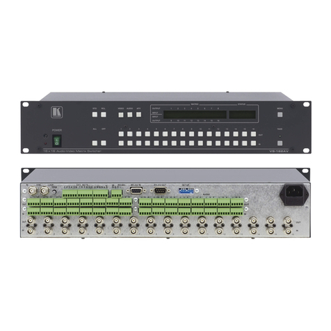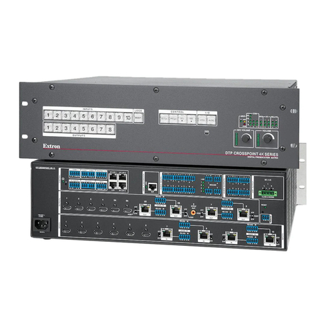
Press to recall the default setup.
11 OUTPUTS/INPUTS
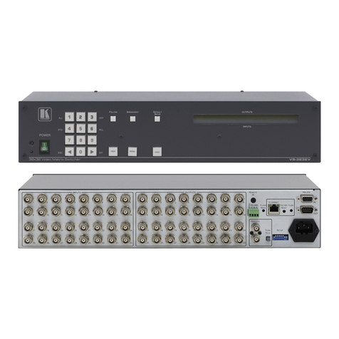
LCD Display
Displays the outputs (upper row) switched to the selected inputs (lower row).
Displays user interface messages and menus.
12 IR Receiver Infrared remote control sensor.
13 IR LED Lights yellow when receiving commands from the IR remote control transmitter.
Press to confirm actions.
15 MENU Button Press once to enable the ALL, OFF, STO and RCL buttons.
Press again to enter the configuration menu.
When in a Menu, press to cycle through the menu items.
16 LOCK Button Press and hold for approximately 2 sec to lock/unlock the front panel buttons.
17 Power Supply Supplies power to the device.
Lights green when power supply is active and the device is powered on.
20 ERROR LED Lights red when an error is detected. Briefly lights red immediately following a power disruption
(e.g., cable disconnection, power off, and so on).
21 ◄ (Backward) Press to shift the display right (the LCD display only shows 13 cross-points out of a total of 32).
1, 2, 3, 4, 5, 6, 7, 8, 9, 0
Press to shift the display left (the LCD display only shows 13 cross-points out of a total of 32).
Fuse holder and power cord socket. Connect to the AC mains supply.
Press to restart the VS-3232DN-EM.
26 USB Virtual Comm Port Mini USB
Connector
Connect to a computer to communicate with the unit and to upgrade the firmware of the
control card and compatible input/output cards.
27 IN 1~16 Connectors INPUTS Connect to the relevant video sources, depending on the cards installed (1 to 16).
Connect to the relevant video sources, depending on the cards installed (7 to 32).
Signal generator module for testing video outputs.
30 RESOLUTION DIP-switches Set the resolution for video generated by the Test module.
31 RS-232 9-pin D-sub Port Connects to the remote operation PC or remote controller.
32 NET Ethernet RJ-45 Connector Connect to a PC or controller via the Ethernet LAN.
The LINK LED flashes when communication is active. The POWER LED
lights when the
interface receives power.
Connect to the relevant video acceptors, depending on the cards installed (1 to 16).
34 OUT 17~32 Connectors Connect to the relevant video acceptors, depending on the cards installed (17 to 32).
35 PATTERN Button Press the button repeatedly to change the video pattern generated by the Test module.
36 Test Module DVI Molex 24-pin Video
Connect to one of the relevant video inputs/outputs to aid in troubleshooting.
