manuals.online logo
Brands
  1. Home
  2. •
  3. Brands
  4. •
  5. Kramer
  6. •
  7. Matrix Switcher
  8. •
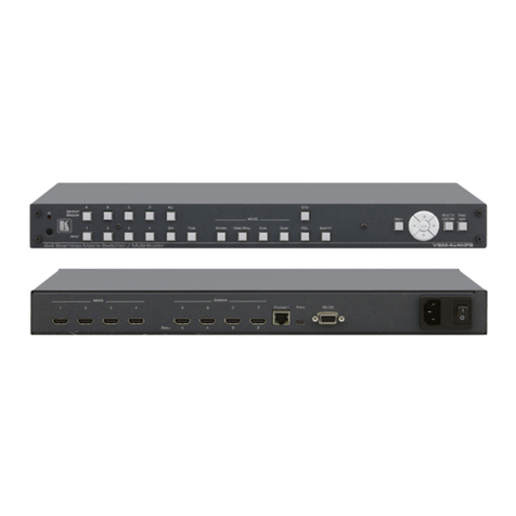
  9. Kramer VSM-4x4A User manual

Kramer VSM-4x4A User manual

Other manuals for VSM-4x4A

1

Other Kramer Matrix Switcher manuals

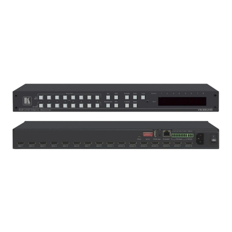
Kramer VS-42H User manual

Kramer

Kramer VS-42H User manual

Kramer VS-84HDCPxl User manual

Kramer

Kramer VS-84HDCPxl User manual

Kramer VP-4x4K User manual

Kramer

Kramer VP-4x4K User manual

Kramer Sierra Video 3232V5 User manual

Kramer

Kramer Sierra Video 3232V5 User manual

Kramer Sierra Video 3216V5 User manual

Kramer

Kramer Sierra Video 3216V5 User manual

Kramer AFM-20DSP User manual

Kramer

Kramer AFM-20DSP User manual

Kramer VSM-4x4X User manual

Kramer

Kramer VSM-4x4X User manual

Kramer VP-8x4AK User manual

Kramer

Kramer VP-8x4AK User manual

Kramer VS-1616D User manual

Kramer

Kramer VS-1616D User manual

Kramer VS-88UHDA User manual

Kramer

Kramer VS-88UHDA User manual

Kramer XL 1608V4S User manual

Kramer

Kramer XL 1608V4S User manual

Kramer Sierra Video 4864V5xl User manual

Kramer

Kramer Sierra Video 4864V5xl User manual

Kramer VS-6464DN-EM User manual

Kramer

Kramer VS-6464DN-EM User manual

Kramer VP-32XLN User manual

Kramer

Kramer VP-32XLN User manual

Kramer XL 1608V4 User manual

Kramer

Kramer XL 1608V4 User manual

Kramer VS-42HDMI User manual

Kramer

Kramer VS-42HDMI User manual

Kramer VS-66H3 User manual

Kramer

Kramer VS-66H3 User manual

Kramer VS-606xl User manual

Kramer

Kramer VS-606xl User manual

Kramer VS-62H User manual

Kramer

Kramer VS-62H User manual

Kramer Sierra Pro XL 1608V3S User manual

Kramer

Kramer Sierra Pro XL 1608V3S User manual

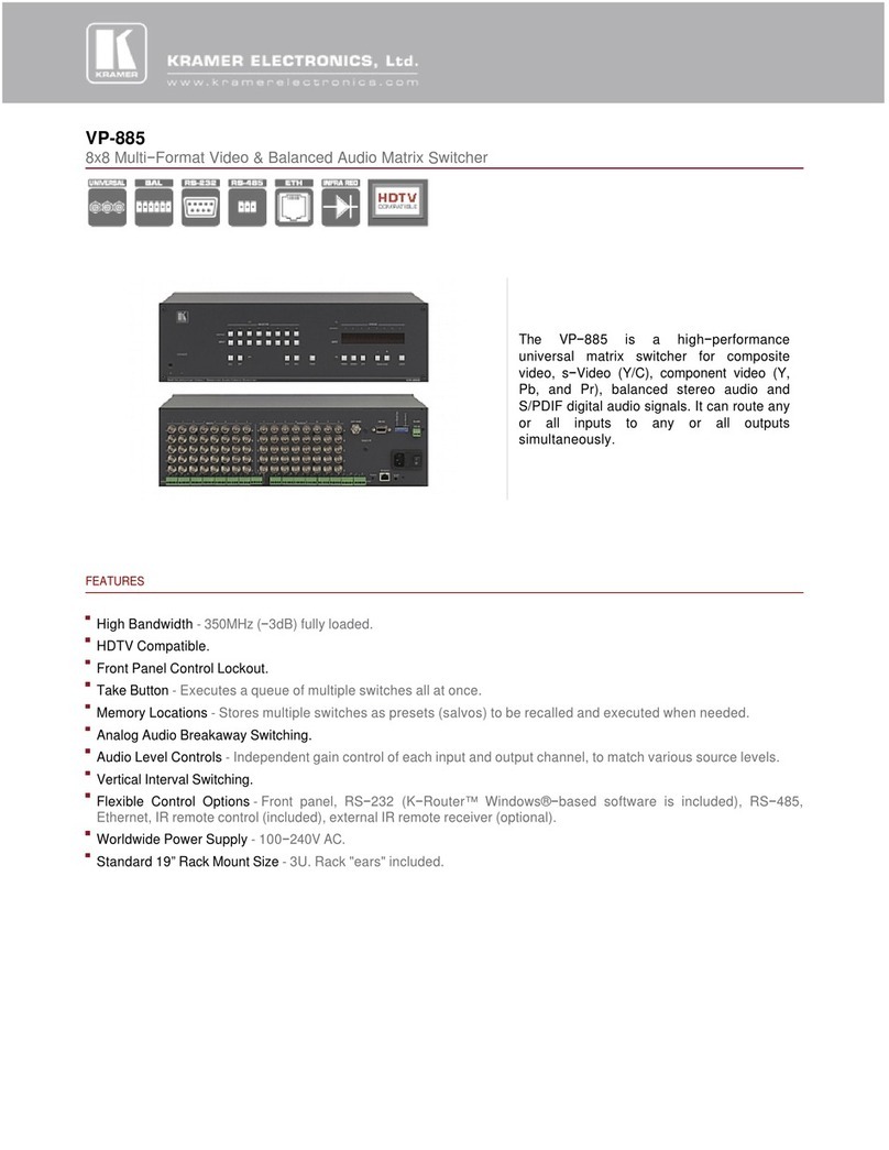
Kramer VP-885 User manual

Kramer

Kramer VP-885 User manual

Kramer Sierra Video 1208V5 User manual

Kramer

Kramer Sierra Video 1208V5 User manual

Kramer VP-719DS User manual

Kramer

Kramer VP-719DS User manual

Kramer LASSEN XL 3232S User manual

Kramer

Kramer LASSEN XL 3232S User manual

Popular Matrix Switcher manuals by other brands

AMX AVS-OCT-3264-210 Product View

AMX

AMX AVS-OCT-3264-210 Product View

Communica CST-2042 user manual

Communica

Communica CST-2042 user manual

Thinklogical TLX48 product manual

Thinklogical

Thinklogical TLX48 product manual

Broadcast Tools SS 8.2 Installation and operation manual

Broadcast Tools

Broadcast Tools SS 8.2 Installation and operation manual

Altimium MATF32 user manual

Altimium

Altimium MATF32 user manual

Monoprice Blackbird 15377 user manual

Monoprice

Monoprice Blackbird 15377 user manual

Link HD8X8 user manual

Link

Link HD8X8 user manual

TESmart HMA0402A40 quick start guide

TESmart

TESmart HMA0402A40 quick start guide

AMX AVS-OP-2020-117 Product View

AMX

AMX AVS-OP-2020-117 Product View

Shinybow USA SB-8811 instruction manual

Shinybow USA

Shinybow USA SB-8811 instruction manual

ALFAtron ALF-MUK44N manual

ALFAtron

ALFAtron ALF-MUK44N manual

Optimus Compact operating instructions

Optimus

Optimus Compact operating instructions

PTN FMX12 user manual

PTN

PTN FMX12 user manual

Lindy 38042 quick start guide

Lindy

Lindy 38042 quick start guide

AMX Precis LT instruction manual

AMX

AMX Precis LT instruction manual

CYP nT15GX01 Operation manual

CYP

CYP nT15GX01 Operation manual

Extron electronics DTP CrossPoint 108 4K user guide

Extron electronics

Extron electronics DTP CrossPoint 108 4K user guide

CYP PUV-662-4K22 Operation manual

CYP

CYP PUV-662-4K22 Operation manual

manuals.online logo
manuals.online logoBrands
  • About & Mission
  • Contact us
  • Privacy Policy
  • Terms and Conditions

Copyright 2025 Manuals.Online. All Rights Reserved.

VSM
-4x4A Quick Start (P/N: 2900-300668QS REV 1)
P/N:
2900- 300668QS
Rev:
1
Scan for full manual
VSM-4x4A Quick Start Guide
Step 1: Check what’s in the box
VSM-4x4A 4x4 Seamless AV Matrix Switcher/Multi-Scaler
1 Set of rack ears
4 Rubber feet
IR remote control transmitter with batteries
1 Power cord
1 Quick start guide
Step 2: Get to know your VSM-4x4A
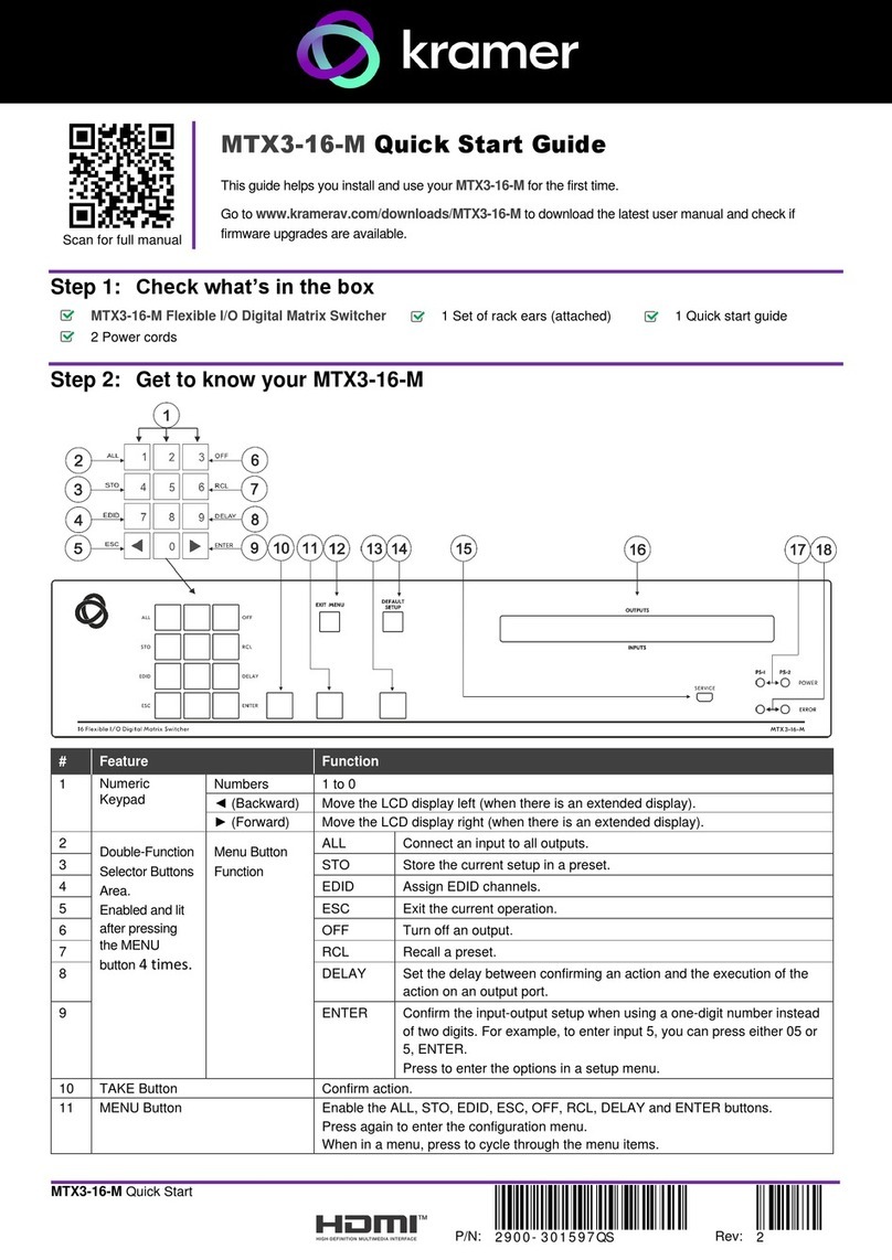
# Feature Function
1 IR LED Lights when the unit accepts IR remote commands
IR Receiver
Receives signals from the remote control transmitter
2 OUTPUT/WINDOW Selector
Buttons MATRIX mode: select the output to which the input is switched (A, B, C or D)
VIDEO WALL mode: not used
DUAL mode: select one of the two DUAL windows: A or B for DUAL A; C or D for DUAL B
QUAD mode: not used
3 INPUT Selector Buttons Press to select an HDMI input (from 1 to 4) to switch to the output
4 ALL Button Press ALL followed by an INPUT button to connect that input to all the outputs (not available for
the video wall mode)
5 OFF Button Press after pressing an output button to disconnect the selected output from the inputs. To
disconnect all the outputs, press ALL followed by OFF
6 TAKE Button Press to toggle between the Confirm mode (when in the Confirm mode, the TAKE button lights )
and the At Once mode. When in TAKE mode, front panel buttons actions are implemented after
pressing the TAKE button
7 MODE
Buttons MATRIX Press to operate the system as a matrix switcher
8
VIDEO WALL
Press to operate as a 2x2 or 1x4 video wall
9
DUAL
Press to operate as a 4x2 switcher with PIP capabilities
10 QUAD Press to display all four inputs on each of the outputs
11 STO Button Press to store a configuration
12
RCL Button
Press to recall a configuration
13 IDENTIFY Button Press to indicate on each output, which input is displayed on the output. The display time is set
via the OSD menu
14 MENU Press to access the OSD menu, exit the OSD menu and, when in the OSD menu, move to the
previous level in the OSD screen
# Feature Function
15
Navigation
Buttons
ENTER
Press to access sub-menu items and select from several settings

Press to decrease numerical values or select from several definitions
Press to move up the menu list values
Press to increase numerical values or select from several definitions

Press to move down the menu list
16
RESET TO XGA/1080p Button
Press and hold for about 4 seconds to toggle resetting the video resolution to XGA or 1080p
17 PANEL LOCK Button Press and hold for about 2 seconds to lock/unlock the front panel buttons
# Feature Function
18 INPUT HDMI Connectors Connect to the HDMI sources (from 1 to 4)
19 AUDIO OUTPUT A 3.5mm Mini Jack Connect to an unbalanced audio acceptor (from A to D)
20
AUDIO OUTPUT 5-pin Terminal Block Connector
Connect to a balanced audio acceptor (from A to D)
21 OUTPUT HDMI Connectors Connect to the HDMI acceptors (from A to D); DUAL: when in the dual
operation mode, A, A and B, B
22 ETHERNET Connector Connects to the PC or other Serial Controller through computer networking
23 PROG USB Connector Connect to upgrade the unit
24
RS-232 9-pin D-sub Port
Connect to the PC or a remote controller
25
Mains Socket
Connect the mains power cord
26 Mains Fuse Holder Fuse for protecting the device
27 Power Switch Switch for turning the unit ON or OFF
Step 3: Install the VSM-4x4A
To rack mount the machine attach both ear brackets to the machine (by removing the three screws
from each side of the machine and replacing those screws through the ear brackets) or place the
machine on a table.
Step 4: Connect one of the four operation modes
Always switch OFF the power on each device before connecting it to your VSM-4x4A. For best results, we recommend that you always
use Kramer high-performance cables to connect AV equipment to the VSM-4x4A.
The VSM-4x4A is a four-in-one-box device and can operate as a matrix switcher, video wall, dual switcher or quad switcher.
Each of these modes includes several setup options as follows.
Mode Optional Setups
MATRIX Seamless Matrix – 4x4 matrix switcher. The same output resolution is set for all the outputs and video switching
transitions are seamless (zero-time video cuts).
Independent Matrix – 4x4 matrix switcher. Each output resolution is set independently and video switching
transitions are done via a clean, fade-through-black mechanism.
VIDEO WALL 2x2 – The output is displayed on a set of 4 monitors tiled in a 2x2 setting to form a large display. Each output shows
one quarter of the image.
1x4 – The output is displayed on a set of 4 monitors tiled in a 1x4 (1 column x 4 rows). The image can be cropped
and positioned as desired.
DUAL 4x2 switcher that outputs 2 identical A outputs and 2 identical B outputs.
POP (side-by-side) – Each A and B type outputs shows 2 images side-by-side (left and right).
PiP
(picture-in-picture) – Each A and B type outputs shows 2 images one over the other (main and pip).
QUAD
Any four inputs on one screen for each of the four outputs. Each quarter of a screen shows a selected input.
RJ-45 Pinout:
Connect the audio output:
For the Ethernet and HDBaseT connectors, see the proper wiring
diagram below To a balanced stereo audio acceptor
To an unbalanced stereo audio
acceptor
PIN EIA /TIA 568B
PIN
1 Orange / White
2
Orange
3
Green / White
4 Blue
5 Blue / White
6
Green
7
Brown / White
8 Brown
Step 5: Connect the power
Connect AC power to the rear of the VSM-4x4A, switch on its power and then switch on the power on each device.
Step 6: Set operation parameters via OSD menu
Menu Function
Enter the OSD menu via the MENU button on the
front panel or the IR remote control transmitter.
Select a menu item and set parameters as
required. By default, the output resolution is set to
Native, the VSM-4x4A is triggered to read the
EDID of OUTPUT A and change the output
resolution value according to the native resolution
of the display.
Mode Set the operation mode: matrix switcher (seamless or
independent), video wall (2x2 or 1x4), Dual (POP or PIP) or
Quad mode.
Picture Set the picture parameters per operation mode (contrast,
brightness saturation and hue): matrix mode (same for all
outputs), video wall (separate for each output), DUAL
(separate for left (main) and right (PIP), QUAD (separate for
each QUAD).
If you cannot see any images, verify that the
display, TV, or projector is in good working order
and is connected to the VSM-4x4A. If you still do
not see an image, press and hold the RESET TO
XGA/1080p button for about 4 seconds to reset
the outputs to XGA or 1080p resolution.
Output Set the output parameters: resolution, aspect ratio, border
color, input and output labels, bezel correction, and so on.
EDID
Manage EDID: per video input as well as audio EDID.
Source Set the input source parameters: matrix mode (any input to
any output), video wall (one input to all outputs), DUAL (an
input for for left (main) and an input for right (PIP), QUAD (any
input for each QUAD).
Recall/ Store Store and recall setups: store/recall up to 4 setups for each
operation mode.
HDCP
Set the HDCP: for each input and each output.
Other settings: set the power-save mode, the output audio level, the OSD
definitions and Ethernet parameters; perform reset to factory default values and
view device information.
Step 7: Operate via the front panel buttons, Web pages and via the:
IR remote controller: RS-232 and Ethernet:
RS-232
Protocol 3000
Baud Rate:
115,200
Stop Bits:
1
Data Bits: 8 Parity: None
TCP/IP Parameters
To reset the IP settings to the factory reset values go to : Menu-> Factory-> RESET->Change
the option to YES and press Enter
IP Address: 192.168.1.39 TCP Port #: Not supported
Subnet mask: 255.255.255.0 Default UDP Port #: 50000
Default gateway: 192.168.1.254 Maximum UDP Ports: 4
Full Factory Reset
OSD Go to : Menu-> FACTORY DEFAULT -> Change the option to YES and
press Enter
P3000
Use “FACTORY” command
Front panel buttons
Press the MENU Button while plugging the power to reset the machine
RS-232/Ethernet (UDP) Command Protocol
Command Format: ASCII
Example (Route the video from the HDMI2 input to the HDMI A output
port in the Matrix mode): #ROUTE 0,1,2<cr>