Kramer KDS-100EN User manual

Kramer Electronics Ltd.
KDS-100 Series – Contents
2
Contents
Contents 2
Introduction 3
Getting Started 3
Overview 4
Typical Applications 5
Controlling your KDS-100 device 6
Defining the KDS-100 7
Defining KDS-100EN 7
Defining KDS-100DEC 9
Mounting KDS-100 11
Connecting KDS-100 12
Connecting KDS-100EN to KDS-100DEC 12
Connecting RS-232 13
Connecting the Audio/Input Output 14
Installing the SFP transceiver (optical SM/MM or copper) 14
Operating and Controlling KDS-100 Devices 15
Configuring the Network Switch 15
Using the Channel Selection Buttons 15
Operating via Ethernet 16
KDS-100EN: Using the Embedded Web Pages 19
Dashboard: Set channel and audio, view input signal 20
Streaming: Multicast settings and time to live 21
Encoding: Method, protocol, scaling, bitrate and more 22
EDID: Set display metadata 24
Gateway: RS-232 settings 25
Device: General device, network and time settings 26
Security: Passwords, HTTPS and 802.1X 29
About: Web version and contact details 32
KDS-100DEC: Using the Embedded Web Pages 33
Dashboard: Set channel and audio, view input signal 34
Video: Decoding method and output resolution 36
External Devices: Connecting External RTSP Streams 37
EDID: Set display metadata 39
Gateway: RS-232 settings 40
Device: General device, network and time settings 41
Security: Passwords, HTTPS and 802.1X 44
About: Web version and contact details 47
Upgrading Firmware 48
Technical Specifications 49
KDS-100EN Specifications 49
KDS-100DEC Specifications 50
Default Communication Parameters 51
Protocol 3000 52
Understanding Protocol 3000 52
Protocol 3000 Commands 53
Result and Error Codes 64

Kramer Electronics Ltd.
KDS-100 Series – Introduction
3
Introduction
Welcome to Kramer Electronics! Since 1981, Kramer Electronics has been providing a world
of unique, creative, and affordable solutions to the vast range of problems that confront the
video, audio, presentation, and broadcasting professional on a daily basis. In recent years, we
have redesigned and upgraded most of our line, making the best even better!
Getting Started
We recommend that you:
•Unpack the equipment carefully and save the original box and packaging materials for
possible future shipment.
•Review the contents of this user manual.
Go to
https://www.kramerav.com/downloads/kds-100en or
https://www.kramerav.com/downloads/kds
-100dec to check for up-to-date user manuals,
application programs, and to check if firmware upgrades are available (where appropriate).
Achieving Best Performance
•Use only good quality connection cables (we recommend Kramer high-performance,
high-resolution cables) to avoid interference, deterioration in signal quality due to poor
matching, and elevated noise levels (often associated with low quality cables).
•Do not secure the cables in tight bundles or roll the slack into tight coils.
•Avoid interference from neighboring electrical appliances that may adversely influence
signal quality.
•Position your Kramer KDS-100EN / KDS-100DEC away from moisture, excessive
sunlight and dust.
Safety Instructions
Caution:
•This equipment is to be used only inside a building. It may only be connected to other
equipment that is installed inside a building.
•For products with relay terminals and GPI\O ports, please refer to the permitted rating
for an external connection, located next to the terminal or in the User Manual.
•There are no operator serviceable parts inside the unit.
Warning:
•If not using PoE, use only the optional power cord supplied for the unit.

Kramer Electronics Ltd.
KDS-100 Series – Introduction
4
Recycling Kramer Products
The Waste Electrical and Electronic Equipment (WEEE) Directive 2002/96/EC aims to reduce
the amount of WEEE sent for disposal to landfill or incineration by requiring it to be collected
and recycled. To comply with the WEEE Directive, Kramer Electronics has made
arrangements with the European Advanced Recycling Network (EARN) and will cover any
costs of treatment, recycling and recovery of waste Kramer Electronics branded equipment on
arrival at the EARN facility. For details of Kramer’s recycling arrangements in your particular
country go to our recycling pages at www.kramerav.com/quality/environment.
Overview
KDS-100 series devices deliver a complete and versatile AVoIP streaming solution for 1GE
(1Gbps) networks making the most of the H.264/265 open standard. KDS-100 is ideal for any
space or use-case requiring low-latency, high-quality video presentation up to 4K60 4:2:2,
such as operations rooms, university auditoriums, highly secure command and control
centers, and AVoIP distribution deployments.
KDS-100 series is extremely bandwidth-efficient, making it perfect for deployment over an
existing IT network. KDS-100 supports up to 1000 video sources, enables simple and fast
deployment, and easily scales to suit any size network AV installation.
Delivering a superior user experience, enterprise IT-grade security and advanced, yet intuitive
management, KDS-100 meets all the streaming needs of enterprise, education, homeland
security, military or government sites of any size. KDS-100 is part of Kramer’s market-leading
KDS family, the broadest range of AVoIP streaming solutions available today
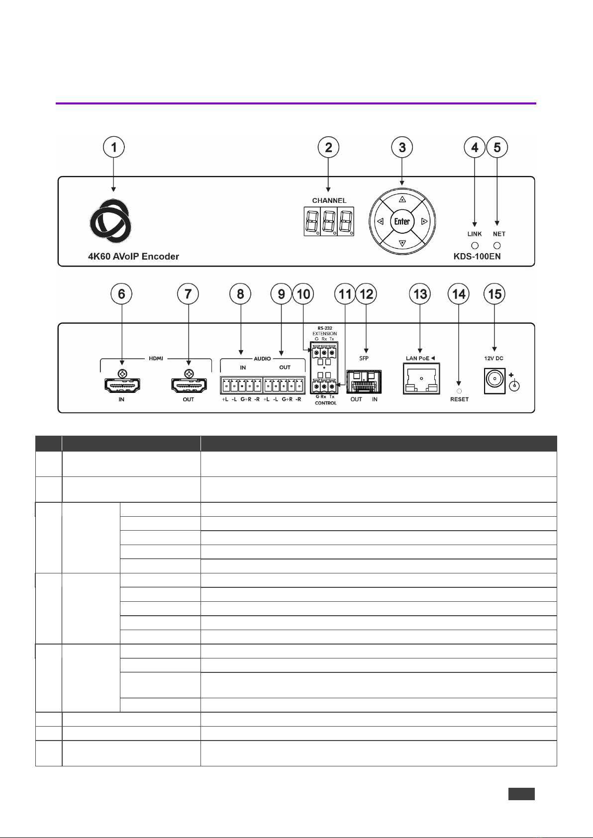
Kramer KDS-100EN is an advanced transmitter for streaming 4K@60Hz video signals via
Ethernet over copper or fiber cables. It encodes and streams over an IP network from HDMI
input, and transmits IR, RS−232 or CEC signals over IP network.
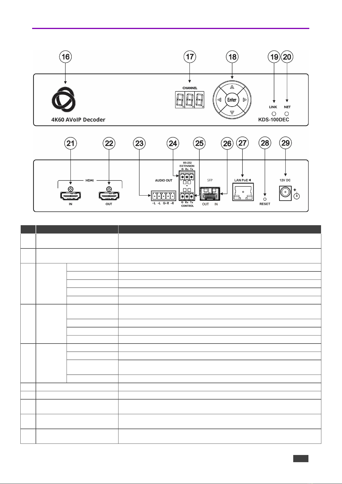
Kramer KDS-100DEC decoder is an advanced receiver for streamed 4K@60Hz video signals
via Ethernet over copper or fiber cables. It also decodes the RS−232 or CEC signals
transmitted over IP network from the encoder.
Highest-Quality Video
Support for 4K60 4:2:2 video streaming ensures finely detailed images are transmitted in full
quality matching the high-end capabilities of displays.
Supports Direct Recording
Allows direct and simple recording of the meeting or transmitted content through network
video recorder (NVR) devices, meeting the requirements of government sites for efficient,
always-activated recording.

Kramer Electronics Ltd.
KDS-100 Series – Introduction
5
Exceptional Quality
•Robust Solution for Large–Scale Installations — The KDS-100 line provides an
optimized solution for large education and enterprise campuses, and for defense and
homeland security facilities, with support for numerous simultaneous video flows and
built–in advanced management capabilities.
•Highly Scalable — The KDS–100 line supports up to 1000 video sources and is suited
for large–scale installations.
•Built–in Resilient Security Features — The KDS–100 line preserves the integrity,
availability and confidentiality of the IT network via a highly secured and resilient AVoIP
solution.
KDS–100 devices comply with IT security requirements, including 802.1x and
HTTPS/TLS.
•Instant switching - Optimized for fast switching between streams. Switching takes just
1 second or less.
Advanced and User-friendly Operation
•Simple Planning and Rollout — KDS–100 is highly bandwidth–efficient, thus enabling
cost–efficient hybrid use of the existing 1GE IT network. There is no need to deal with
complex IP packets prioritization or switching settings. Offering easy management, high
reliability, and adjustable bandwidth control, KDS–100 is extremely cost–effective to
maintain over the long term.
•Alternative Sources/Destinations — An HDMI loop–through port on the encoder side
and an HDMI input port on the decoder, as well as embedding and de–embedding
analog audio to the IP stream.
Typical Applications
KDS-100EN is ideal for the following typical applications:
•Real-time essential installations such as command and control rooms.
•Large scale AV content sharing installations using existing wires and infrastructure in
corporate offices and government applications.
•AV distribution systems with one or more sources and multiple displays in schools,
universities, and public venues.

Kramer Electronics Ltd.
KDS-100 Series – Introduction
6
Controlling your KDS-100 device
Control your KDS-100 device via:
•The Ethernet using built-in user-friendly web pages: See Operating via Ethernet
on page 16.
•Protocol 3000 (API) commands: See Protocol 3000 on page 52.
•Use the channel selection button to set the broadcast channel: See Using the
Channel Selection Buttons on page 15.

Kramer Electronics Ltd.
KDS-100 Series – Defining the KDS-100
7
Defining the KDS-100
Defining KDS-100EN
Figure 1: KDS-100EN
#
Feature
Function
1
ON LED (behind the logo)
On when power is supplied to the unit by PoE+ or by the (optional) power
adapter.
2
CHANNEL 7-segment display
Use to set the stream’s channel (channels must match on encoder and
decoder).
3
Channel
Selection
Button
Up
Press to increment the channel ID number by 1.
Down
Press to decrement the channel ID number by 1.
Right
Press to increment the channel ID number by steps of 10.
Left
Press to decrement the channel ID number by steps of 10.
Enter
Press to accept the new channel ID number (within 10 seconds).
4 LINK LED
Off
No HDMI input is detected, or AV streaming mode is OFF for KDS-100EN.
Lights green
KDS-100EN is linked to a decoder and streaming is active.
Lights blue
KDS-100EN is in Dual Streaming mode, but one of the streams is not active.
Lights red
Streaming is not active (in Dual Streaming mode, both streams are inactive).
Flashes green
A device identification command was sent (Flag me). Flashes for 60 seconds.
5 NET LED
Off
No network connection detected.
Lights green
A network has been detected and KDS-100EN has a valid IP address
Lights red
A network has been detected but the device was not assigned a valid IP
address (configure with an RS-232 interface).
Flashes green
A device identification command was sent (Flag me). Flashes for 60 seconds.
6
HDMI IN connector
Connect to an HDMI source.
7
HDMI OUT connector
Connect to an HDMI acceptor.
8
AUDIO IN
5-pin terminal block
Connect to a balanced, stereo audio source (for example, from the server).

Kramer Electronics Ltd.
KDS-100 Series – Defining the KDS-100
8
#
Feature
Function
9
AUDIO OUT
5-pin terminal block
Connect to a balanced, stereo audio acceptor (for example, active speakers).
10
RS-232 EXTENSION 3-pin
terminal block connector
Connect to a serial data source or acceptor to extend RS-232 control from
KDS-100EN to a KDS-100DEC.
11
RS-232 CONTROL
3-pin terminal block connector
Connect to a serial controller or PC and use it to control KDS-100EN with
P3000 API commands.
12
SFP OUT IN transceiver
connector
Insert an SFP transceiver (optical SM/MM or copper) and plug in an optical /
CAT-6e cable for Ethernet traffic over IP.
13
LAN PoE ◄ RJ-45 Port
Connect to the LAN (Ethernet traffic or PC controller).
KDS-100EN is powered by PoE+ (power over ethernet) delivered through the
LAN PoE port, unless the optional 12V DC power adapter is attached.
14
RESET recessed button
Press and hold for 10 seconds to restore factory default values. All LEDs flash.
15
12V DC connector
Connect to the optional power adapter (purchased separately).

Kramer Electronics Ltd.
KDS-100 Series – Defining the KDS-100
9
Defining KDS-100DEC
Figure 2: KDS-100DEC 4K60 AVoIP Decoder
#
Feature
Function
16
ON LED (behind the logo)
On when power is supplied to the unit by PoE+ or by the (optional) power
adapter.
17 CHANNEL 7-segment display
Use to set the stream’s channel (channels must match on encoder and
decoder).
18
Channel
Selection
Button
Up
Scroll up through the list of automatically discovered channels.
Down
Scroll down through the list of automatically discovered channels.
Right
No action.
Left
No action.
Enter
Press to accept the new channel ID number (within 10 seconds).
19 LINK LED
Off
No network streaming detected, or AV streaming mode is OFF for
KDS-100DEC
Lights green
KDS-100DEC is receiving an input stream and decoding is successful.
Lights red
KDS-100DEC is receiving an input stream but decoding has failed.
Flashes green
A device identification command was sent (Flag me). Flashes for 60 seconds.
20 NET LED
Off
No network connection detected.
Lights green
Network detected and the device has been assigned a valid IP address
Lights red
A network has been detected but the device was not assigned a valid IP
address (configure with an RS-232 interface).
Flashes green
A device identification command was sent (Flag me). Flashes for 60 seconds.
21
HDMI IN connector
Connect to an HDMI source.
22
HDMI OUT connector
Connect to an HDMI acceptor.
23
AUDIO OUT
5-pin terminal block
Connect to a balanced, stereo audio acceptor (for example, active speakers).
24
RS-232 EXTENSION
3-pin terminal block connector
Connect to a serial data source or acceptor to extend RS-232 control from
KDS-100DEC to KDS-100-EN.
25
RS-232 CONTROL
3-pin terminal block connector
Connect to a serial controller or PC to control KDS-100DEC.

Kramer Electronics Ltd.
KDS-100 Series – Defining the KDS-100
10
#
Feature
Function
26
SFP OUT IN transceiver
connector
Insert an SFP transceiver (optical SM/MM or copper) and plug in an optical /
CAT-5e cable for Ethernet traffic over IP.
27 LAN PoE ◄ RJ-45 Port
Connect to the LAN (Ethernet traffic or PC controller).
KDS-100DEC is powered by PoE+ (power over ethernet) delivered through
the LAN PoE+ port, unless the optional 12V DC power adapter is attached.
28 RESET recessed button
Press and hold for 10 seconds to restore factory default values. All LEDs
flash.
29
12V DC connector
Connect to the power adapter (purchased separately).

Kramer Electronics Ltd.
KDS-100 Series – Mounting KDS-100
11
Mounting KDS-100
This section provides instructions for mounting the devices. Before installing, verify that the
environment is within the recommended range:
•Operation temperature – 0°to 40°C (32 to 104°F).
•Storage temperature – -40°to +70°C (-40 to +158°F).
•Humidity – 10% to 90%, RHL non-condensing.
Caution:
•Mount the devices before connecting any cables or power.
Warning:
•Ensure that the environment (e.g., maximum ambient temperature & air flow) is
compatible for the device.
•Avoid uneven mechanical loading.
•Appropriate consideration of equipment nameplate ratings should be used for avoiding
overloading of the circuits.
•Reliable earthing of rack-mounted equipment should be maintained.
•Maximum mounting height for the device is 2 meters.
Mounting KDS-100 devices in a rack:
•Use the recommended rack adapter
(see https://www.kramerav.com/product/kds-100en#Tab_Application_Story or
https://www.kramerav.com/product/kds-100dec#Tab_Application_Story).
Mount KDS-100 devices on a surface using one of the following
methods:
•Attach the rubber feet and place the unit on a flat surface.
•Fasten a
bracket (included) on each side of the unit and attach it to
a flat surface.

Kramer Electronics Ltd.
KDS-100 Series – Connecting KDS-100
12
Connecting KDS-100
By
default, KDS-100 devices use PoE+ for power. An optional power adapter can be
purchased separately
to connect the product to the mains electricity.
Always
switch off the power to a device before connecting it to your KDS-100 device.
Connecting KDS-100EN to KDS-100DEC
Figure 3: Connecting KDS-100EN to KDS-100DEC

Kramer Electronics Ltd.
KDS-100 Series – Connecting KDS-100
13
To connect KDS-100EN and KDS-100DEC as illustrated in the example Figure 3:
1. Connect an HDMI source (for example, a server or a media player) to the encoder’s
HDMI IN connector (see Defining the KDS-100 on page 7).
2. Connect a balanced stereo audio source (for example, the server audio connector) to
the encoder’s AUDIO IN/OUT 5-pin terminal block connector (see Defining the KDS-
100 on page 7).
3. Connect the LAN MEDIA 1G(PoE) RJ-45 port on the encoder to a LAN switch.
4. Connect the LAN MEDIA 1G(PoE) RJ-45 port on the decoder to the same LAN
switch.
5. Connect the HDMI OUT connector on the KDS-100DEC to an HDMI acceptor (for
example, a display).
6. Connect the AUDIO OUT 5-pin terminal block connector on the KDS-100DEC to a
balanced stereo audio acceptor (for example, an audio amplifier).
7. Connect RS-232 3-pin terminal block connectors:
On the KDS-100EN, connect the RS-232 port to a control device such as the SL-
240C.
On the KDS-100DEC, connect RS-232 to a device that can be controlled by RS-
232.
Connecting RS-232
KDS-100 devices feature an RS-232 3-pin terminal block connector on their rear panel
which can be used to transmit RS-232 data between the encoder and decoder and to
remotely control connected devices.
Connect the RS-232 terminal block on the rear panel to a PC/controller, as follows:
From the RS-232 9-pin D-sub serial port connect:
RS
-232 bidirectional signals can be sent between the encoder and decoder.
•Pin 2 to the TX pin on the RS-232 terminal block
•Pin 3 to the RX pin on the RS-232 terminal block
•Pin 5 to the G pin on the RS-232 terminal block
RS-232 Device
6
8
13
27
22
23
10
24
11

Kramer Electronics Ltd.
KDS-100 Series – Connecting KDS-100
14
Connecting the Audio/Input Output
The following are the pinouts for connecting the input/output to a balanced or unbalanced
stereo audio acceptor:
Figure 4: Connecting to a
Balanced Stereo Audio
Source/Acceptor
Figure 5: Connecting to an
Unbalanced Stereo Audio Acceptor
Figure 6: Connecting an
Unbalanced Stereo Audio Source
to the Balanced Input
Installing the SFP transceiver (optical SM/MM or
copper)
1. Remove the currently installed transceiver: Pull down the bale clasp, insert the dust plug and
pull out. Store in a safe place.
2. Make sure the bale clasp of the new transceiver is pushed up, in the closed position.
3. Insert the new transceiver into the SFP port and push it in until it clicks.
4. Remove the dust plug and store it in a safe place for future use.
Figure 7: Inserting the SFP transceiver
Warning:
•Connecting the SFP transceiver to an LC(APC) fiber connector may cause poor performance
and damage the connector!
Warning: Class 1 Laser Product
•Invisible laser radiation present.
•Avoid long-term viewing of laser.
•Avoid the use of magnifying viewing aids or instruments (such as binoculars, telescopes,
microscopes, and magnifying lenses, but not spectacles or contact lenses).
•Avoid placing optical devices in the emitted beam that could cause the concentration of the laser
radiation to be increased.

Kramer Electronics Ltd.
KDS-100 Series – Operating and Controlling KDS-100 Devices
15
Operating and Controlling KDS-
100 Devices
This section describes the following actions:
•Configuring the Network Switch on page 15.
•Using the Channel Selection Buttons on page 15.
•Operating via Ethernet on page 16.
Configuring the Network Switch
Make sure that your AV over IP network switch meets the following minimum requirements:
•IGMP Snooping – On.
•IGMP Immediate/Fast Leave – On.
•Unregistered Multicast Filtering – On.
•PoE+ (unless using the optional power supply)
Using the Channel Selection Buttons
Each encoder requires a unique channel number. Decoders connected to the encoder must be
tuned to the same channel as the encoder. You can set the channel number with the Channel
Selection button (shown in the image) or the embedded web pages.
Setting the channel number with the channel selection button:
1. For the KDS-100EN:
a) Use the UP/DOWN arrows to increment/decrement the channel
number by 1 and the RIGHT/LEFT buttons to increment/decrement by 10. Channel
selections that collide with an existing channel will not be accepted.
b) Press ENTER (while the CHANNEL display flashes) to accept the changes.
oChannel selections that collide with an existing channel will not be accepted.
oThe CHANNEL display flashes for 10 seconds and the new channel ID is displayed.
oIf ENTER is not pressed within the 10-second flashing period, or if an error occurs,
the channel ID is not changed.
2. On each connected KDS-100DEC:
oSet the same channel number defined on the KDS-100EN: Use the UP/DOWN
arrows to scroll up or down through the list of automatically detected channels.
oIf Dual Stream mode is activated on KDS-100EN, both output streams have the
same Channel ID.
oThe CHANNEL display flashes for 10 seconds, press Enter while it flashes to
confirm the selection.

Kramer Electronics Ltd.
KDS-100 Series – Operating and Controlling KDS-100 Devices
16
Operating via Ethernet
This section describes the following actions:
•Accessing the embedded web pages on page 16.
•Connecting the Ethernet Port Directly to a PC on page 17.
•Connecting Ethernet Port via a Network Hub or Switch on page 18.
•Configuring Ethernet Port on page 18.
Accessing the embedded web pages
Each KDS-100 device contains an embedded HTML menu which provides extensive device
controls. The embedded web pages are accessed by entering the IP of the KDS-100 device in
a browser within the same network or on a computer directly connected to the KDS-100
device.
To access the embedded web pages, perform the following:
1. Connect the LAN port of the KDS-100 device to a local area network.
2. By default, DHCP sets the IP of your KDS-100 device and you may need to ask your
network administrator to identify its IP address.
If no DHCP server is available, for example if the device is connected directly to a PC, it
will use the default IP addresses (192.168.1.39 for the encoder and 192.168.1.40 for the
decoder).
3. Connect your PC to the same network as the encoder / decoder.
4. Input the encoder or decoder’s IP address in the browser and press Enter, if Security is
enabled (default), the Login window pops up.
Figure 8: Login Window
4. Input the username and password (default username / password: Admin / Admin) and
click Sign In to enter the main page of embedded web pages.
You have accessed the embedded web pages.

Kramer Electronics Ltd.
KDS-100 Series – Operating and Controlling KDS-100 Devices
17
Connecting the Ethernet Port Directly to a PC
You can connect the encoder/decoder Ethernet port directly to the Ethernet port on your PC
using a crossover Ethernet cable with RJ-45 connectors.
This type of connection
causes KDS-100EN and KDS-100DEC to use their factory
configured default IP address.
After connecting the KDS-100 device to the PC’s Ethernet port, configure your PC as follows:
1. Click Start > Settings > Network and Internet.
2. Click Change Adapter Options.
3. Highlight the network adapter you want
to use to connect to the device and click
Change settings of this connection.
The Local Area Connection Properties
window for the selected network adapter
appears as shown in Figure 9.
4. Highlight either Internet Protocol
Version 6 (TCP/IPv6) or Internet
Protocol Version 4 (TCP/IPv4)
depending on the requirements of your IT
system.
Figure 9: Local Area Connection Properties Window
5. Click Properties.
The Internet Protocol Properties
window relevant to your IT system
appears as shown in Figure 10 or
Figure 11.
Figure 10: Internet Protocol Version 4 Properties
Window

Kramer Electronics Ltd.
KDS-100 Series – Operating and Controlling KDS-100 Devices
18
Figure 11: Internet Protocol Version 6 Properties Window
6. Select Use the following IP Address for static IP addressing and fill in the details as
shown in Figure 12.
For TCP/IPv4 you can use any IP address in the range 192.168.1.1 to 192.168.1.255
(excluding 192.168.1.39) that is provided by your IT department.
Figure 12: Internet Protocol Properties Window
7. Click OK and then click Close.
Connecting Ethernet Port via a Network Hub or Switch
You can connect the KDS-100 Ethernet port to the Ethernet port on a network hub or using a
straight-through cable with RJ-45 connectors.
Configuring Ethernet Port
Ethernet parameters are best set using the embedded web pages. P3000 API commands can
also be used.

Kramer Electronics Ltd.
KDS-100 Series – KDS-100EN: Using the Embedded Web Pages
19
KDS-100EN: Using the Embedded
Web Pages
KDS-100EN enables you to configure settings using the built-in, user-friendly, Ethernet web
pages. The web pages are accessed using a web browser and an Ethernet connection.
For the decoder web pages, s
ee KDS-100DEC: Using the Embedded Web Pages
on
page 33.
KDS
-100EN can also be configured by Protocol 3000 commands (see Protocol 3000
Commands
on page 53).
For instructions on how to connect to the encoder and load the web pages, see Operating via
Ethernet on page 16.
If a web page does not update correctly, clear
the browser cache.
Some features m
ay not be supported by mobile device operating systems.
To Browse the KDS-100EN Web Pages:
1. Open your Internet browser.
2. Type the IP number of the device in the address bar of
your browser. For example, the default IP number:
If Security is enabled in the Security pabe, then the Login
window appears. Figure 13: Login Window
3. Enter the Username and Password (default Admin / Admin).
The KDS-100EN page
appears.
4. Click the tabs on the
left to select a
relevant web page.
Figure 14: Dashboard Window

Kramer Electronics Ltd.
KDS-100 Series – KDS-100EN: Using the Embedded Web Pages
20
Dashboard:
Set channel and audio, view input signal
The KDS-100EN Dashboard shows an overview of AV streaming and audio information. Use
the dashboard to set the streaming channel, mode and audio parameters.
To set the streaming channel:
1. In the Dashboard pane, activate AV
Streaming.
2. Define the following settings:
Streaming Mode: Dual outputs the
stream twice, with the second stream
at a lower bandwidth and higher
latency. Additional options are set in
the Streaming pane and the
Encoding pane.
Channel ID: Enter a channel in
Manual mode or move the slider to
Automatic and the device will select
the first unused channel.
The channel ID (1 to 899) must be
identical on encoder and decoder.
Additional fields are displayed to describe the input AV.
3. Click the green check to confirm your changes.
To set the audio volume:
•Volume: Use the slider to adjust the analog
audio output volume (0 to 100%).
Default is 70%. 100% is 12dB and 0% is
mute.
•Mute: Mute/unmute all audio outputs (HDMI
OUT, AUDIO OUT, and MEDIA ports).
To set the audio output’s source:
•In the INPUTS dropdown, select from HDMI IN, Analog Audio Input and None.
This manual suits for next models
1
Table of contents
Other Kramer Media Converter manuals

Kramer
Kramer VP-420 User manual

Kramer
Kramer KDS-EN6 User manual

Kramer
Kramer VP-419XL User manual

Kramer
Kramer 401C User manual

Kramer
Kramer VM-2HDCPxl User manual

Kramer
Kramer VP-501XL User manual

Kramer
Kramer DigiTOOLS VM-2HDMI User manual

Kramer
Kramer VP-409 User manual

Kramer
Kramer VM-1010 User manual

Kramer
Kramer Tools 482xl User manual

Kramer
Kramer OC-1N User manual

Kramer
Kramer VM-4UX User manual

Kramer
Kramer FC-7501 User manual

Kramer
Kramer FC-16 User manual

Kramer
Kramer VP-724DS User manual

Kramer
Kramer KDS-USB2 Kit User manual

Kramer
Kramer FC-17 User manual

Kramer
Kramer VP-425 User manual

Kramer
Kramer VP-427H2 User manual

Kramer
Kramer VA-11 User manual