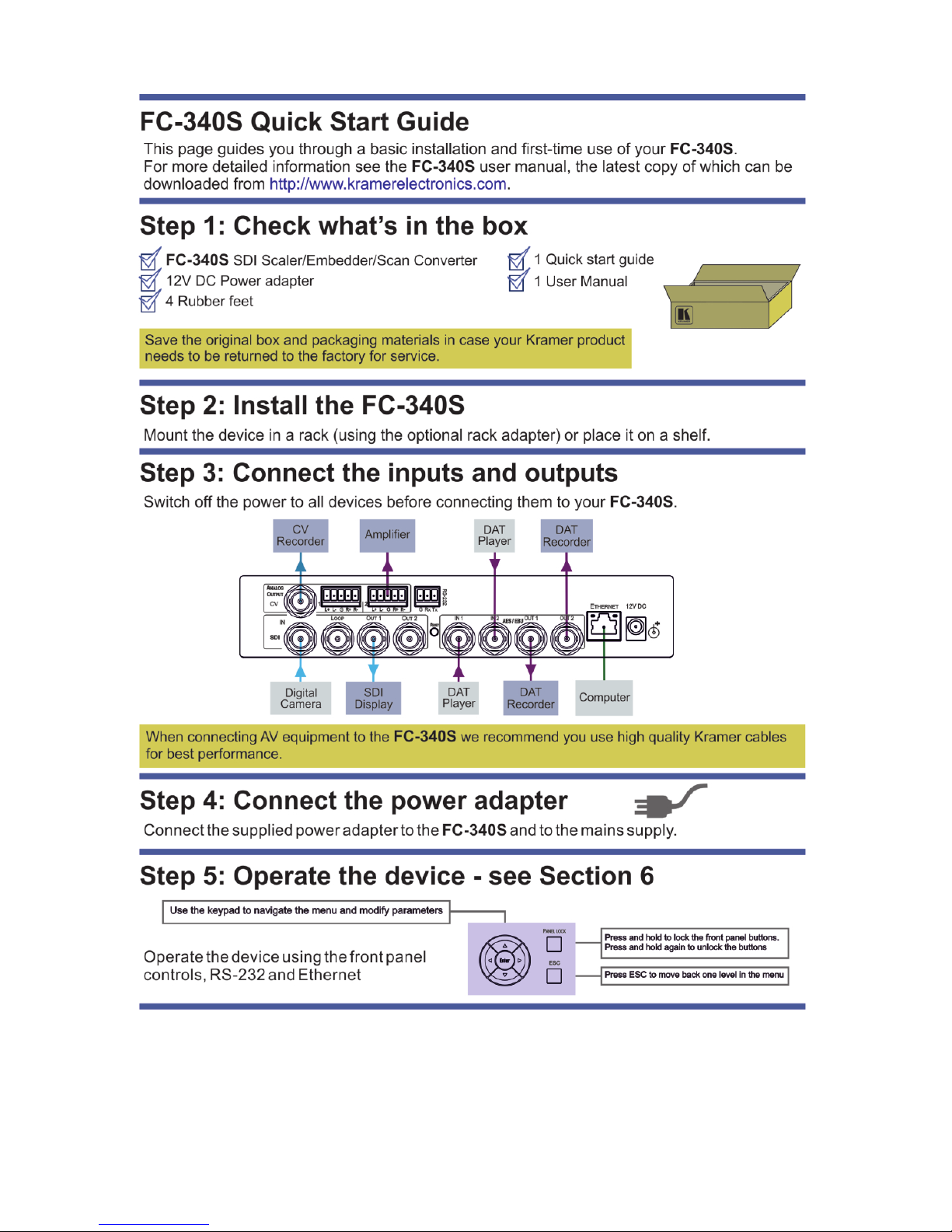
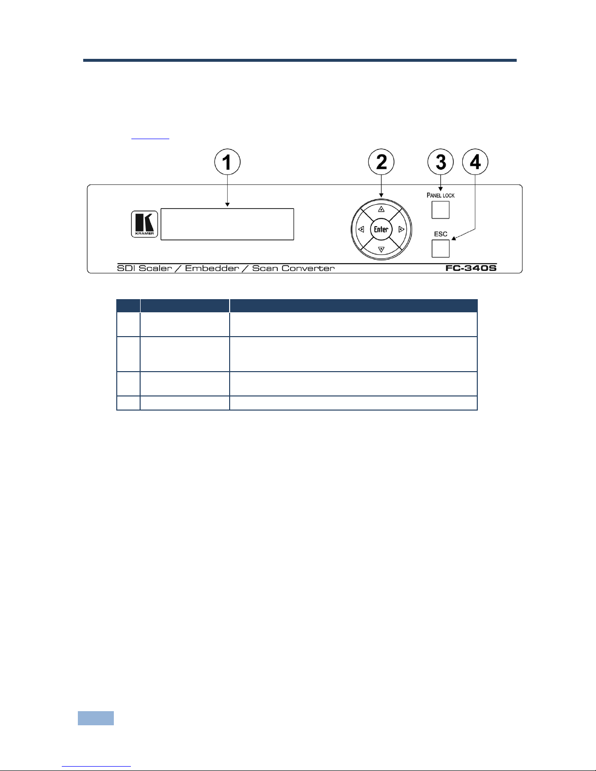
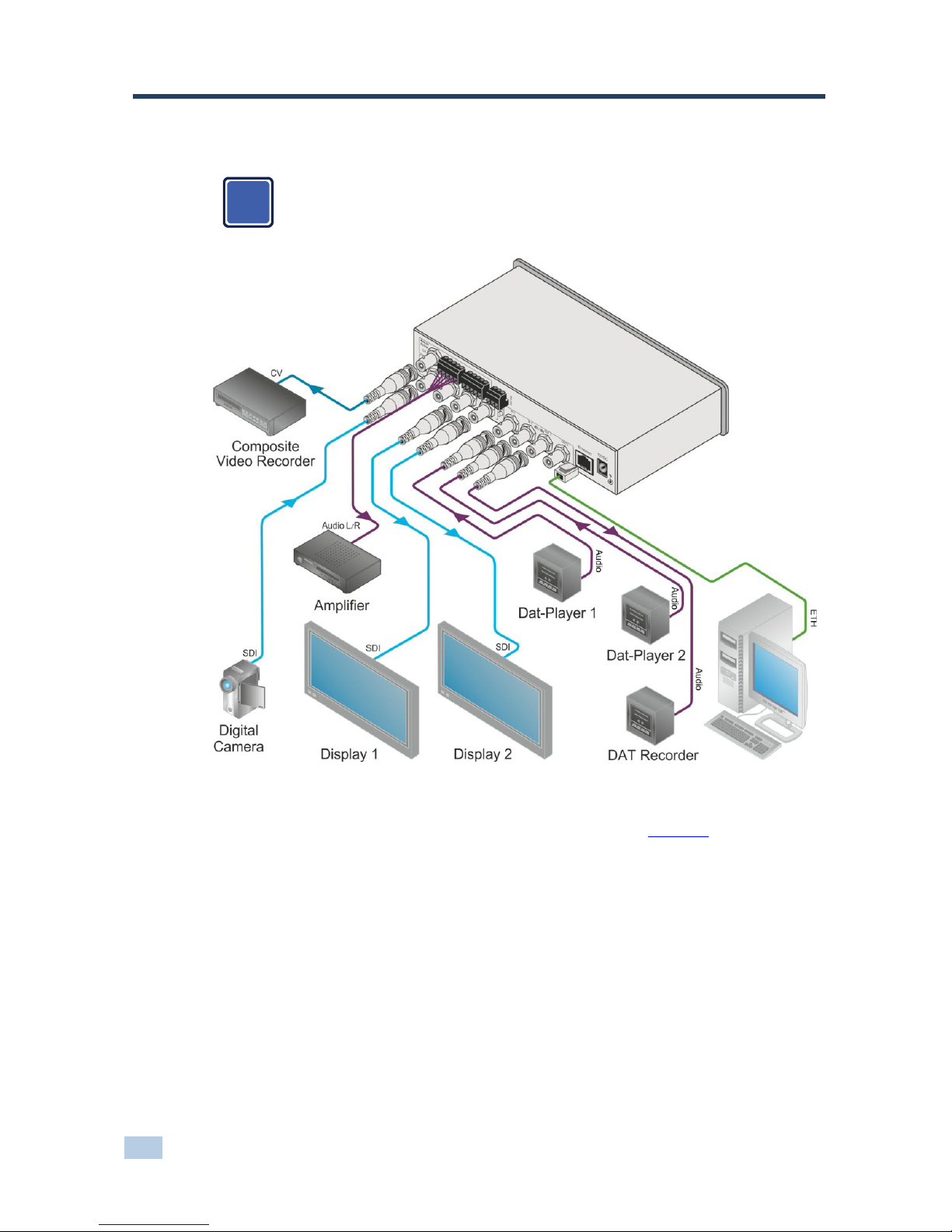
Kramer FC-340S User manual

KRAMER ELECTRONICS LTD.
USER MANUAL
MODEL:
FC-340S
SDI Scaler/Embedder/Scan
Converter
P/N: 2900-300082 Rev 2


FC-340S – Contents i
Contents
1Introduction 1
2Getting Started 2
2.1 Achieving the Best Performance 2
3Overview 3
4Defining the FC-340S SDI Scaler/Embedder/Scan Converter 4
5Connecting the FC-340S 6
5.1 Connecting a Serial Controller to the FC-340S 7
5.2 Connecting to the FC-340S via Ethernet 7
5.3 Connecting the Balanced/Unbalanced Stereo Audio Output 10
6Operating the FC-340S 11
6.1 Changing the Output Resolution 11
6.2 Using the Menu 12
6.3 To Reset the Device to Factory Default Configuration 14
6.4 Locking and Unlocking the Front Panel 14
6.5 Updating the Firmware Using the K-Upload Software 15
7Technical Specifications 16
8Default Parameters 17
8.1 Default Communication Parameters 17
9Kramer Protocol 18
9.1 Protocol 3000 Syntax 18
9.2 Command Part Details 19
9.3 Kramer Protocol 3000 Commands 20
Figures
Figure 1: FC-340S SDI Scaler/Embedder/Scan Converter Front Panel 4
Figure 2: FC-340S SDI Scaler/Embedder/Scan Converter Rear Panel 5
Figure 3: Connecting the FC-340S SDI Scaler/Embedder/Scan Converter 6
Figure 4: Local Area Connection Properties Window 8
Figure 5: Internet Protocol (TCP/IP) Properties Window 9
Figure 6: Balanced Stereo Audio Connection 10
Figure 7: Unbalanced Stereo Audio Connection 10

FC-340S - Introduction
1
1 Introduction
Welcome to Kramer Electronics! Since 1981, Kramer Electronics has been
providing a world of unique, creative, and affordable solutions to the vast range of
problems that confront video, audio, presentation, and broadcasting professionals
on a daily basis. In recent years, we have redesigned and upgraded most of our
line, making the best even better!
Our 1,000-plus different models now appear in 11 groups that are clearly defined
by function: GROUP 1: Distribution Amplifiers; GROUP 2: Switchers and Routers;
GROUP 3: Control Systems; GROUP 4: Format/Standards Converters; GROUP
5: Range Extenders and Repeaters; GROUP 6: Specialty AV Products; GROUP
7: Scan Converters and Scalers; GROUP 8: Cables and Connectors; GROUP 9:
Room Connectivity; GROUP 10: Accessories and Rack Adapters and GROUP 11:
Sierra Video Products.
Congratulations on purchasing your FC-340S SDI Scaler/Embedder/Scan
Converter which is ideal for broadcast and production studios as well as
digital/analog AV authoring.

2
FC-340S - Getting Started
2 Getting Started
We recommend that you:
•Unpack the equipment carefully and save the original box and packaging
materials for possible future shipment
•Review the contents of this user manual
Use Kramer high performance, high resolution cables
Go to http://www.kramerelectronics.com to check for up-to-date
user manuals, application programs and to check whether firmware
upgrades are available (where appropriate).
2.1 Achieving the Best Performance
To achieve the best performance:
•Use only good quality connection cables to avoid interference, deterioration
in signal quality due to poor matching, and elevated noise levels (often
associated with low quality cables)
•Do not secure the cables in tight bundles or roll the slack into tight coils
•Avoid interference from neighboring electrical appliances that may adversely
influence signal quality
•Position your Kramer FC-340S away from moisture, excessive sunlight and
dust
Caution: No operator serviceable parts inside the unit
Warning: Disconnect the power and unplug the unit from the wall
before installing
i
!

FC-340S - Overview
3
3 Overview
The FC-340S SDI Scaler/Embedder/Scan Converter is ideal as a broadcast
quality video scaler and audio embedder/de-embedder for digital signals up to 3G
HD-SDI.
All mentions of SDI in this manual include signals up to and including 3G HD-SDI.
The FC-340S features:
•A maximum data rate of 3Gpbs
•One SDI video input and two scaled SDI video outputs
•One re-clocked looping video output
•One composite video output
•One balanced audio output
•Two AES/EBU audio inputs and two AES/EBU audio outputs
•The option to select either the embedded audio or to embed two
independent audio groups
•Kramer reKlocking™ & Equalization Technology that rebuilds the digital
signal to travel longer distances
•An LCD text display for easy configuration and operation

4
FC-340S - Defining the FC-340S SDI Scaler/Embedder/Scan Converter
4 Defining the FC-340S SDI
Scaler/Embedder/Scan Converter
Figure 1 defines the front panel of the FC-340S.
Figure 1: FC-340S SDI Scaler/Embedder/Scan Converter Front Panel
# Feature Function
1 LCD Readout Displays either the input/output resolution currently
selected or the menu during configuration
2 Menu Navigation
Buttons
Press the Enter, up (▲), down (▼), left (◄) and right (►)
buttons to navigate the menu, and modify parameters or
values
3 PANEL LOCK
Button
Press and hold to lock the front panel buttons. Press and
hold again to unlock the buttons
4 ESC Button Press to move back one level through the menu

FC-340S - Defining the FC-340S SDI Scaler/Embedder/Scan Converter
5
Figure 2 defines the rear panel of the FC-340S.
Figure 2: FC-340S SDI Scaler/Embedder/Scan Converter Rear Panel
# Feature Function
1 ANALOG
OUTPUT CV
CV BNC Video
Connector
Connect to a composite video acceptor (see the
Note in Section 6.1)
2 5-pin Terminal Block 1 Connect to a balanced audio acceptor
3 5-pin Terminal Block 2 Connect to a balanced audio acceptor
4 RS-232 3-pin Serial Port Terminal
Block
Connect to a serial controller
5 ETHERNET RJ-45 Connector Connect to a PC controller via a LAN
6 IN SDI BNC Connector Connect to an SDI signal source
7 LOOP BNC Connector Connect to an SDI acceptor
8 OUT 1 BNC Connector Connect to an SDI acceptor
9 OUT 2 BNC Connector Connect to an SDI acceptor
10 RESET Button Press and hold while switching on the device to
reset to factory default parameters
(see Section 8)
11
AES/EBU
IN 1 BNC Connector Connect to an AES/EBU audio source
12 IN 2 BNC Connector Connect to an AES/EBU audio source
13 OUT 1 BNC Connector Connect to an AES/EBU audio acceptor
14 OUT 2 BNC Connector Connect to an AES/EBU audio acceptor
15 12V DC Power Socket Connect to the power adapter

6
FC-340S - Connecting the FC-340S
5 Connecting the FC-340S
Always switch off the power to any device before connecting it to your
FC-340S. After connecting your FC-340S, connect its power and then
switch on the power to the other devices.
Figure 3: Connecting the FC-340S SDI Scaler/Embedder/Scan Converter
To connect the FC-340S as illustrated in the example in Figure 3:
1. Connect an SD/HD/3G HD-SDI source (for example, an HD digital video
camera) to the SDI IN BNC connector.
2. Connect the SDI OUT 1 BNC connector to an SDI acceptor (for example, an
SDI display).
3. Connect the SDI OUT 2 BNC connector to an SDI acceptor (for example, an
SDI display).
i

FC-340S - Connecting the FC-340S
7
7
4. Connect the CV ANALOG OUTPUT BNC connector to a composite video
acceptor (for example, a composite video recorder). See the Note in
Section 6.1.
5. Connect the 5-pin terminal block to a balanced audio acceptor (for example,
an amplifier).
6. Connect AES digital audio sources (for example, DAT players) to the
AES/EBU IN 1 and IN 2 BNC connectors.
7. Connect the AES/EBU OUT 1 BNC connector to an AES digital audio
acceptor (for example, a DAT recorder).
8. Optional—Connect a controller via either RS-232 and/or a LAN to the
Ethernet RJ-45 connector.
5.1 Connecting a Serial Controller to the FC-340S
You can connect to the FC-340S via an RS-232 connection using, for example, a
PC.
To connect to the FC-340S via RS-232:
•Connect the 3-pin terminal block on the rear panel port of the FC-340S (pin
G to pin 5, pin Rx to pin 3, pin Tx to pin 2) to the RS 232 9-pin D-sub port on
your PC
5.2 Connecting to the FC-340S via Ethernet
You can connect the FC-340S via Ethernet via either of the following methods:
•A crossover cable (see Section 5.2.1) for direct connection to the PC
•A straight through cable (see Section 5.2.2) for connection via a network hub
or network router
After connecting the Ethernet port, you have to install and configure your Ethernet Port. For
detailed instructions, see the Ethernet Configuration Guide (Lantronix) in the technical support
section on our Web site http://www.kramerelectronics.com.

8
FC-340S - Connecting the FC-340S
5.2.1 Connecting the Ethernet Port directly to a PC
You can connect the Ethernet port on the FC-340S to the Ethernet port on your
PC via a crossover cable with RJ-45 connectors. This type of connection is
recommended for identification of the factory default IP Address of the FC-340S
during the initial configuration.
To configure your PC after connecting the Ethernet port:
1. Right-click the My Network Places icon on your desktop.
2. Select Properties.
3. Right-click Local Area Connection Properties.
4. Select Properties.
The Local Area Connection Properties window appears.
5. Select the Internet Protocol (TCP/IP) and click the Properties Button.
Figure 4: Local Area Connection Properties Window

FC-340S - Connecting the FC-340S
9
9
6. Select Use the following IP Address and enter the details as shown in
Figure 5.
Figure 5: Internet Protocol (TCP/IP) Properties Window
7. Click OK.
5.2.2 Connecting to the Ethernet Port via a Network Switch/Hub
To connect to the Ethernet port on the FC-340S via a network switch/hub:
•Connect the PC to the Ethernet network switch/hub using a straight through
cable

10
FC-340S - Connecting the FC-340S
5.3 Connecting the Balanced/Unbalanced Stereo Audio
Output
Figure 6 and Figure 7 illustrate how to wire the devices to the balanced audio
output.
Figure 6: Balanced Stereo
Audio Connection
Figure 7: Unbalanced
Stereo Audio Connection

FC-340S - Operating the FC-340S
11
11
6 Operating the FC-340S
In general operation, the video signal received on the SDI IN connector is output
simultaneously on both SDI OUT connectors as well as the composite video
ANALOG OUTPUT connector. The audio embedded in the SDI input signal is
output on both AES/EBU connectors simultaneously as well as on the balanced
audio ANALOG OUTPUT.
When the FC-340S is powered on, the following is displayed briefly:
FC340S
KRAMER
The device then performs a self test. If the test is successful the Menu is displayed
as shown below.
VIDEO OUT >
AUDIO OUT >
If there is no button activity for approximately 30 seconds, the display reverts to
displaying the input status and output resolution similar to that shown below:
IN unlocked
OUT 1080p59.94
6.1 Changing the Output Resolution
To change the output resolution:
1. Press the Enter button to display the menu.
The menu is displayed.
2. Using the up (▲) or down (▼) button, move through the menu options until
the flashing cursor is on Video Out.

12
FC-340S - Operating the FC-340S
3. Press Enter.
The Video Out options are displayed.
4. Using the up (▲) or down (▼) button, move through the Video Out options
until the flashing cursor is on Resolution.
5. Press Enter.
The Resolution options are displayed.
6. Using the up (▲) or down (▼) button, select the required output resolution.
7. Press Enter.
The selected output resolution is saved.
Note: The CV output follows the frame rate of the selected resolution. For 50Hz
resolutions the PAL standard is used, and for 59.94/60Hz resolutions NTSC is used.
6.2 Using the Menu
The menu is shown on the display when the Enter button is pressed. If there is no
button activity for approximately 30 seconds, display reverts back to the
Input/Output display.
Navigation through the menu is performed as follows:
•Enter—display the menu or select a parameter/value
•Up (▲) or Right (►)—scroll up through the parameter/value list
•Down (▼) or Left (◄)—scroll down through the parameter/value list
•ESC—Move to the first level menu
The main menu comprises six sections:
•Video Out (see Section 6.2.1)
•Audio Out (see Section 6.2.2)
•Status (see Section
6.2.3)
•Comm Settings (see Section
6.2.4)
•System (see Section 6.2.5)

FC-340S - Operating the FC-340S
13
13
6.2.1 Video Out Sub-menu
The parameters in the Video Out sub-menu set the output video characteristics.
Parameter Description Options
Resolution Sets the output
resolution
1080p59.94, 1080p60, 1080p50, NTSC, PAL,
720p59.94, 720p60, 720p50, 1080i59.94,
1080i60, 1080i50
Default—720p59.94
Genlock
Mode
Sets the source for
the genlock signal
No Genlock, Input
Default—No Genlock
Note: The CV output frame rate follows the above settings (see Section 6.1).
6.2.2 Audio Out Sub-menu
The parameters in the Audio Out sub-menu set the audio output characteristics.
Parameter Description Options
Embedding > Sets the audio group to embed Group 1, Group 2, Group 3, Group 4
Default—Off
AES Out 1 Embeds the AES audio input 1. Default—Off
AES Out 2 Embeds the AES audio input 2. Default—Off
6.2.3 Status Sub-menu
The parameters in the Status sub-menu display the input conditions.
Parameter Description Options
Video Input > Displays the locked/unlocked status of
the video format and genlock
Format Unlocked
Genlock Unlocked
Audio Input Displays the audio group status G1 G2 G3 G4
6.2.4 Comm Settings Sub-menu
The parameters in the Comm Settings sub-menu set the network IP and display
the serial communications values.
Parameter Description Options
NETWORK IP address Sets the IP network address All valid IP addresses
Default—192.168.001.039
IP mask Sets the IP network mask All valid subnets
Default—255.255.000.000
IP gateway Sets the IP gateway address All valid gateway addresses
Default—000.000.000.000
IP port Sets the IP port number All valid TCP ports
Default—05000
RS-232 Baud Displays the baud rate 115200
Parity Displays the parity bit setting none

14
FC-340S - Operating the FC-340S
6.2.5 System Sub-menu
The parameters in the System sub-menu display the device versions and set the
LCD display characteristics.
Parameter Description
FIRMWARE The device firmware version
FPGA VER The device FPGA version
S/N The device serial number
6.3 To Reset the Device to Factory Default Configuration
To reset the device to the factory default configuration:
1. Turn the device off.
2. Press and hold the Reset button on the rear panel of the device.
3. While holding the button depressed, turn the device on.
4. Hold the button depressed for 10 seconds and release the button.
The configuration is reset to the factory default.
6.4 Locking and Unlocking the Front Panel
You can lock the front panel buttons to prevent unwanted key presses from
changing the current configuration.
To lock the front panel:
•Press and hold the Panel Lock button.
The button lights, the Locked message is displayed briefly, and the front
panel buttons are locked. Pressing any button causes the Locked message
to display briefly and the Panel Lock button to flash
To unlock the front panel:
•Press and hold the Panel Lock button.
The button no longer lights and the front panel buttons are unlocked

FC-340S - Operating the FC-340S
15
15
6.5 Updating the Firmware Using the K-Upload Software
The FC-340S uses a microcontroller that runs firmware located in flash memory.
The latest version of firmware and upgrade instructions (Kramer K-Upload Guide)
can be downloaded from the Kramer Web site at
http://www.kramerelectronics.com.

16
FC-340S - Technical Specifications
7 Technical Specifications
INPUTS:
Digital
Video
1 SDI serial video, 75Ω on
BNC connectors
SD
SMPTE-259M
SMPTE-125M
480i–59.94
ITU-R BT.656-5 576i–50
HD
SMPTE-292
SMPTE-296M
720p–59.94/60/50
SMPTE-274M
1080i–59.94/60/50
1080p–29.97/30/2
23.98/24
23.98sF/24sF
3G
SMPTE-424M
SMPTE-296M
1080p–59.94/60/50
Max. input level: 800mVpp /75Ω
Digital
Audio
2 AES-3id audio on BNC
connectors
Sample conversion rate: 48kHz
OUTPUTS: Digital
Video
2 SDI video, 75Ω on BNC
connectors
SD SMPTE-259M
SMPTE-125M
480i–59.94
ITU-R BT.656-5 576i–50
HD SMPTE-292M
SMPTE-296M
720p–59.94/60/50
SMPTE-274M 1080i–59.94/60/50
3G
SMPTE-424M
SMPTE-296M
1080p–59.94/60/50
Max. output level: 800mVpp /75Ω
Analog
Video
1 Composite on a BNC connector, PAL/NTSC (according to output frame rate)
Digital
Audio
2 AES-3id audio on BNC
connectors
Sample conversion rate: 48kHz
Analog
Audio
2 Balanced stereo audio on a 5-pin terminal block Bandwidth: 20kHz
POWER CONSUMPTION: 12V DC, 1A
OPERATING TEMPERATURE: 0° to +55°C (32° to 131°F)
STORAGE TEMPERATURE: –45° to +72°C (–49° to 162°F)
HUMIDITY: 10% to 90%, RHL non-condensing
DIMENSIONS: 21.5cm x 16.7cm x 4.4cm (8.46” x 6.57” x 1.73”) W, D, H
WEIGHT: 1.6kg (3.53lbs) approx.
ACCESSORIES: Power supply
OPTIONS: Rack mount kit RK-1

FC-340S - Default Parameters
17
17
8 Default Parameters
8.1 Default Communication Parameters
RS-232
Baud Rate 115,200
Data Bits 8
Stop Bits 1
Parity None
Command Format ASCII
Example (Output 1 to Input 1) #AV 1>1<CR>
Ethernet
To reset the IP settings to the factory reset values, power cycle the
device while holding in the Factory Reset button located on the rear
panel of the unit
IP Address 192.168.1.39
Subnet mask 255.255.255.0
Default gateway 192.168.1.1
TCP Port # 5000
UDP Port # 50000
Maximum UDP Ports 10
Maximum TCP Ports 4
Table of contents
Other Kramer Media Converter manuals

Kramer
Kramer DigiTOOLS 6410N User manual

Kramer
Kramer VM-24HC User manual

Kramer
Kramer VM-80HP User manual

Kramer
Kramer VP-428H2 User manual

Kramer
Kramer VM-1110xl User manual

Kramer
Kramer VM-312 User manual

Kramer
Kramer VP-424C User manual

Kramer
Kramer VP-451 User manual

Kramer
Kramer FC-101Net User manual

Kramer
Kramer VP-451 User manual

Kramer
Kramer VP-409 User manual

Kramer
Kramer FC-20 User manual

Kramer
Kramer FC-101Net User manual

Kramer
Kramer VP-426H2 User manual

Kramer
Kramer TOOLS FC-47 User manual

Kramer
Kramer VM-28H User manual

Kramer
Kramer FC-331 User manual

Kramer
Kramer FC-4046 User manual

Kramer
Kramer FC-49 User manual

Kramer
Kramer FC-113 User manual