Kramer VS-121HCA User manual

Kramer Electronics, Ltd.
USER MANUAL
Model:
VS-121HCA
12 x 1 Stereo Audio - S/PDIF Switcher

Contents
i
Contents
1Introduction 1
2Getting Started 1
2.1 Quick Start 2
3Overview 3
4Your VS-121HCA Stereo Audio S/PDIF Switcher 3
5Installing the VS-121HCA in a Rack 6
6Connecting the VS-121HCA 7
7Operating the VS-121HCA 8
7.1 Operating Using the Front Panel Buttons 9
7.2 Operating via the RS-232 Port 9
7.2.1 Connecting the RS-232 Port 9
7.3 Operating via the RS-485 Port 10
7.3.1 Setting the Address Switches 11
7.3.2 Setting the Line Termination 11
7.4 Operating via the ETHERNET Port 12
7.4.1 Connecting the ETHERNET Port directly to a PC (Crossover Cable) 12
7.4.2 Connecting the ETHERNET Port via a Network Hub (Straight-Through Cable) 13
7.4.3 Configuring the Ethernet Port 13
7.5 Operating via the Infrared Remote Controller 13
7.5.1 Adjusting the Input Volume 14
7.6 Setting the DIP-switches 14
7.7 Operating the VS-121HCA in Tandem with the VS-121HC 16
8Technical Specifications 17
9Upgrading the VS-121HCA Firmware 18
9.1 Upgrading the Device Firmware 18
9.1.1 Downloading from the Internet 18
9.1.2 Connecting a PC to the RS-232 Port 18
9.1.3 Installing the Device Firmware 19
9.2 Upgrading the Ethernet Firmware 23
9.2.1 Downloading from the Internet 24
9.2.2 Connecting the PC to the RS-232 Port 24
9.2.3 Installing the Ethernet Firmware 25
10 Hex Tables 26
11 Kramer Protocol 2000 27

KRAMER: SIMPLE CREATIVE TECHNOLOGY
Contents
ii
Figures
Figure 1: VS-121HCA 12 x 1 Stereo Audio - S/PDIF Switcher 4
Figure 2: Connecting the VS-121HCA Stereo Audio S/PDIF Switcher 8
Figure 3: Crossed Cable RS-232 Connection 10
Figure 4: Straight Cable RS-232 Connection with a Null Modem Adapter 10
Figure 5: Master/Slave Configuration 11
Figure 6: Local Area Connection Properties Window 12
Figure 7: Internet Protocol (TCP/IP) Properties Window 13
Figure 8: Product DIP-switches 14
Figure 9: Operating the VS-121HCAA in Tandem with the VS-121HC 16
Figure 10: Splash Screen 19
Figure 11: Atmel – Flip Window 20
Figure 12: Device Selection Window 20
Figure 13: Device Selection Window 21
Figure 14: Loading the Hex 21
Figure 15: RS-232 Window 22
Figure 16: Atmel – Flip Window (Connected) 22
Figure 17: Atmel – Flip Window (Operation Completed) 23
Figure 18: The KFR-Programmer Window 25
Tables
Table 1: VS-121HCA Front Panel Features 5
Table 2: VS-121HCA Rear Panel Features 5
Table 3: DIP-switch Settings 15
Table 4: Machine Number DIP-switch Settings 15
Table 5: VS-121HCA Technical Specifications 17
Table 6: Communication Parameters 17
Table 7: VS-121HCA Hex Table 26
Table 8: VS-121HCA Increase/Decrease Audio Gain Hex Table 26
Table 9: Protocol Definitions 27
Table 10: Instruction Codes for Protocol 2000 28

Introduction
1
1
1 Introduction
Welcome to Kramer Electronics! Since 1981, Kramer Electronics has been
providing a world of unique, creative, and affordable solutions to the vast
range of problems that confront the video, audio, presentation, and
broadcasting professional on a daily basis. In recent years, we have
redesigned and upgraded most of our line, making the best even better! Our
1,000-plus different models now appear in 11 groups1
Thank you for purchasing the Kramer VS-121HCA 12 x 1 Stereo Audio -
S/PDIF Switcher. This product is ideal for the following typical
applications:
that are clearly
defined by function.
•Presentation and conference rooms, board rooms and auditoriums
•Production studios, rental and staging
•Home cinema
The package includes the following items:
•VS-121HCA 12 x 1 Stereo Audio - S/PDIF Switcher
•Power cord2
•Windows®-based Kramer control software
, null-modem adapter and rack ears
3
•RC-IR2 Infrared remote control transmitter (including the required
battery and a separate user manual
4)
•This user manual4
2 Getting Started
We recommend that you:
•Unpack the equipment carefully and save the original box and
packaging materials for possible future shipment
•Review the contents of this user manual
•Use Kramer high performance high-resolution cables5
1 GROUP 1: Distribution Amplifiers; GROUP 2: Switchers and Matrix Switchers; GROUP 3: Control Systems; GROUP 4:
Format/Standards Converters; GROUP 5: Range Extenders and Repeaters; GROUP 6: Specialty AV Products; GROUP 7:
Scan Converters and Scalers; GROUP 8: Cables and Connectors; GROUP 9: Room Connectivity; GROUP 10: Accessories
and Rack Adapters; GROUP 11: Sierra Products
2 We recommend that you use only the power cord supplied with this device
3 Downloadable from our Web site at http://www.kramerelectronics.com
4 Download up-to-date Kramer user manuals from our Web site: http://www.kramerelectronics.com
5 The complete list of Kramer cables is on our Web site at http://www.kramerelectronics.com

KRAMER: SIMPLE CREATIVE TECHNOLOGY
Getting Started
2
2.1 Quick Start
This quick start chart summarizes the basic setup and operation steps.

Overview
3
3
3 Overview
The Kramer VS-121HCA is a high-quality 12 x 1 Stereo Audio - S/PDIF
Switcher designed for home cinema applications. The VS-121HCA inputs up to
12 S/PDIF digital audio and 12 analog audio channels and switches them to one
S/PDIF and one analog output. The digital and analog audio channels switch
together and are not converted into the other format. The VS-121HCA is also a
companion product to the VS-121HC 12 x 1 Component Video Switcher /
-Transcoder in addition to its use as a standalone switcher/transcoder. The
VS-121HCA features:
•12 S/PDIF digital audio inputs on RCA connectors that switch to 1
S/PDIF digital audio output on an RCA connector
•12 analog audio inputs on terminal blocks that switch to 1 analog audio
output on a terminal block
•A front panel with 12 input selector buttons, as well as a panel lock
button to prevent unintentional tampering with the front panel
•Individual volume control on each input adjusted by IR remote control
or RS-232. The volume settings are saved in non-volatile memory
•The ability to operate it in tandem with the VS-121HC
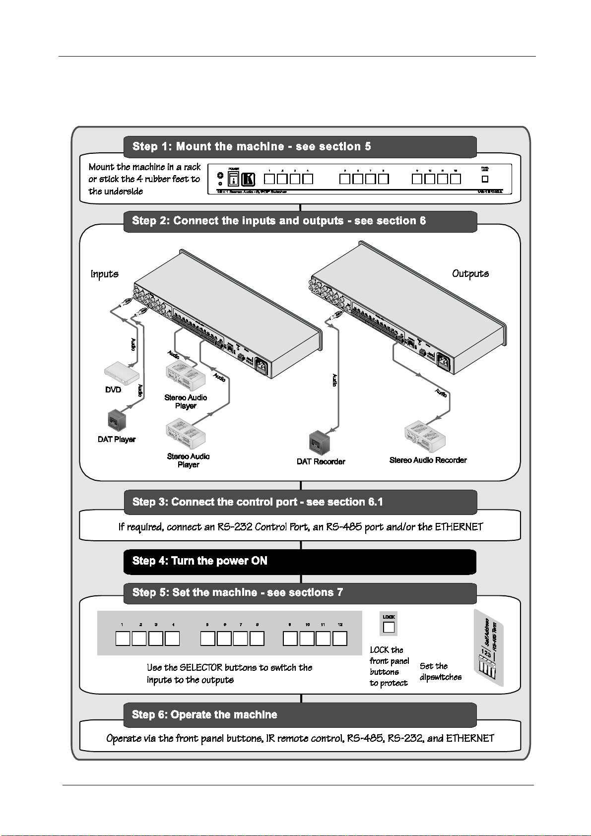
Operate the VS-121HCA using the front panel buttons, or remotely using:
•RS-232 and RS-485 serial commands transmitted by PC, a touch screen
system, or other serial controller
•The ETHERNET
•The Kramer Infrared remote control transmitter
The VS-121HCA is housed in a 19” 1U rack-mountable enclosure, and is
powered by a 100-240 VAC universal switching power supply.
To achieve the best performance:
•Use only good quality connection cables1
•Avoid interference from neighboring electrical appliances that may
adversely influence signal quality and position your
VS-121HCA away from moisture, excessive sunlight, and dust
to avoid interference,
deterioration in signal quality due to poor matching, and elevated noise
levels (often associated with low quality cables)
4 Your VS-121HCA Stereo Audio S/PDIF Switcher
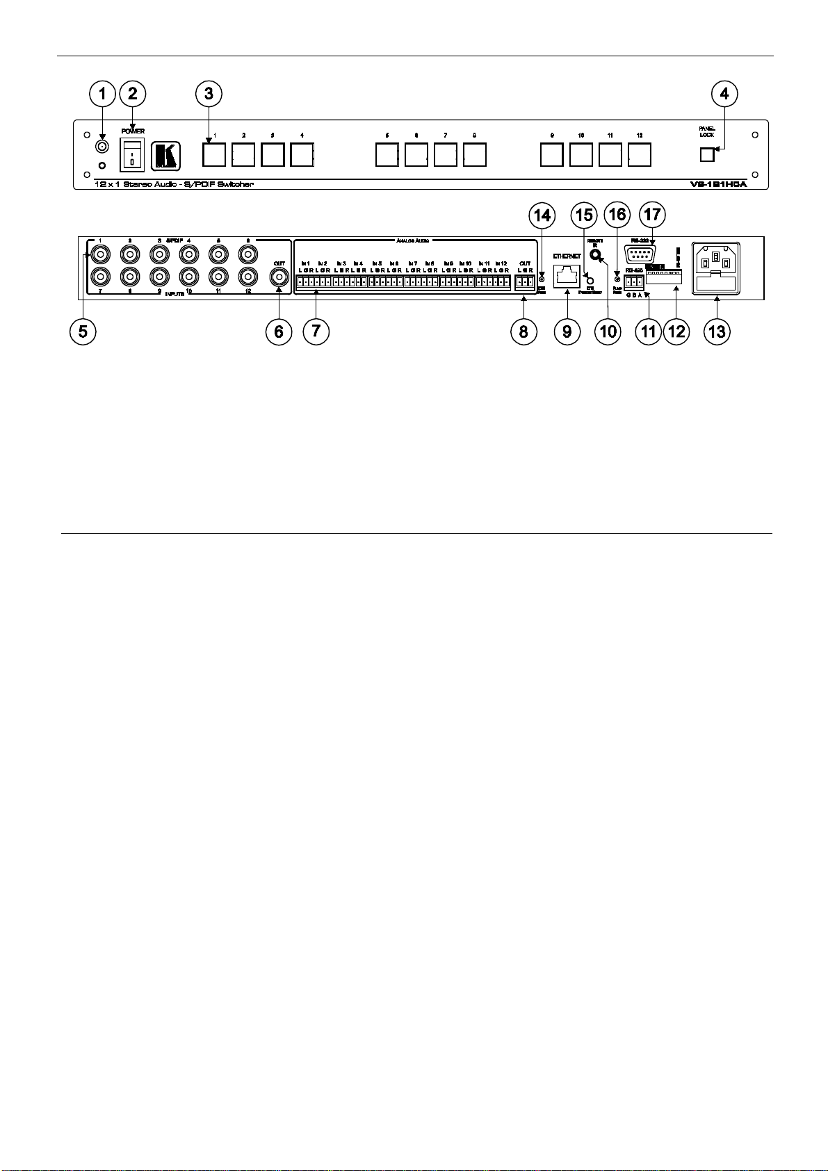
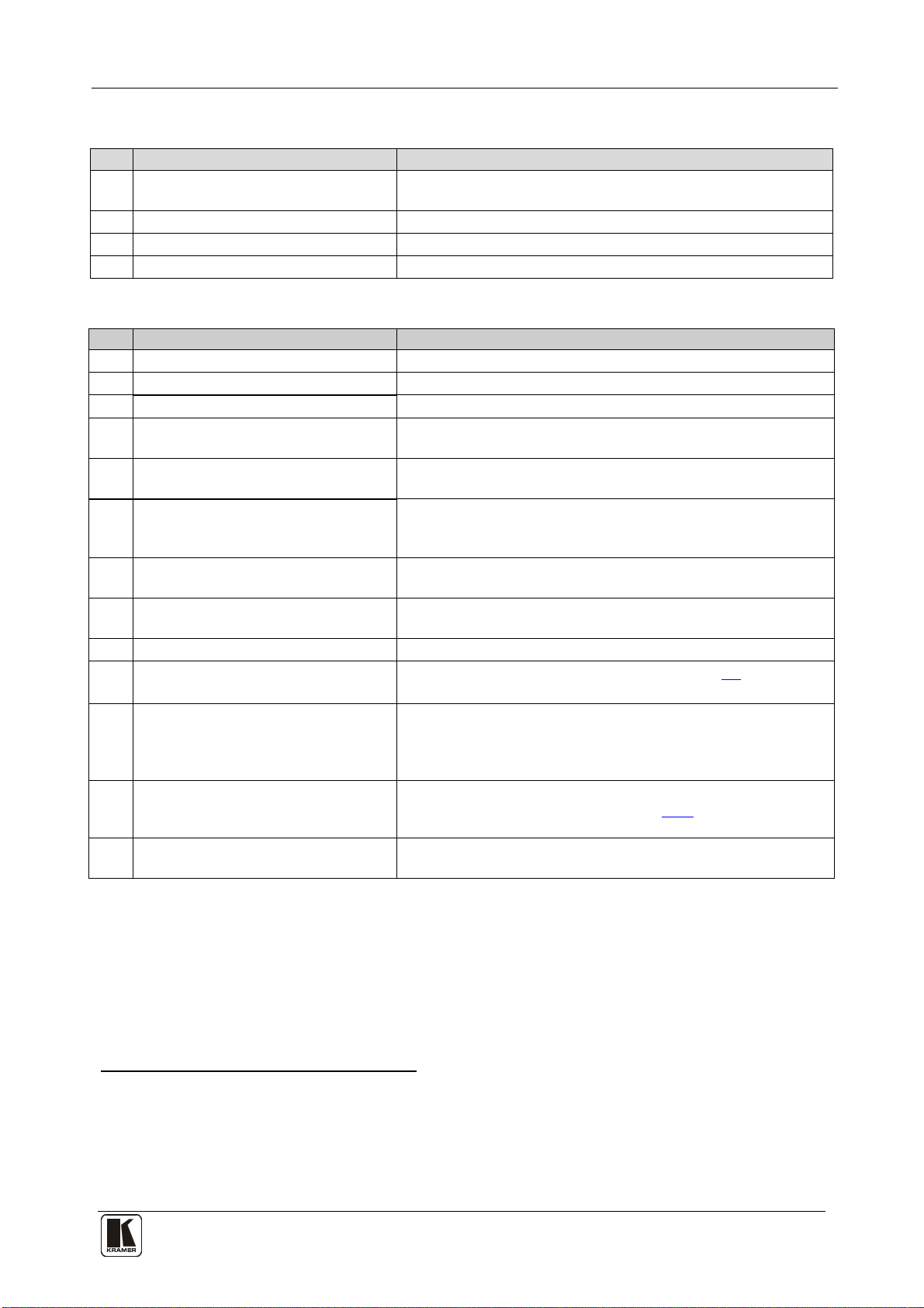
Figure 1,Table 1,and Table 2 define the front and rear panels of the
VS-121HCA 12 x 1 Stereo Audio - S/PDIF Switcher.
1 Available from Kramer Electronics on our Web site at http://www.kramerelectronics.com

KRAMER: SIMPLE CREATIVE TECHNOLOGY
Your VS-121HCA Stereo Audio S/PDIF Switcher
4
Figure 1: VS-121HCA 12 x 1 Stereo Audio - S/PDIF Switcher

Your VS-121HCA Stereo Audio S/PDIF Switcher
5
Table 1: VS-121HCA Front Panel Features
#
Feature
Function
1 IR Receiver The red LED is illuminated when receiving signals from the
Infrared remote control transmitter
2 POWER Switch Illuminated switch for turning the unit ON or OFF
3 Input Selector Buttons Select the audio input (1 to 12) to switch to the outputs
4 PANEL LOCK Button Disengages/engages the front panel buttons
Table 2: VS-121HCA Rear Panel Features
#
Feature
Function
5 S/PDIF INPUT RCA Connectors Connect to the digital audio source (1 to 12)
6 S/PDIF OUT RCA Connector Connect to digital audio acceptor
7 ANALOG AUDIO IN Terminal BlocksConnect to analog audio source (IN1 to IN12)
8 ANALOG AUDIO OUT Terminal
Block Connect to analog audio acceptor
9 ETHERNET RJ-45 Connector Connects to the PC or other Controller through computer
networking LAN
10 REMOTE IR 3.5mm Mini Jack Connect to an external IR receiver unit for controlling the machine
via an IR remote controller (instead of using the front panel IR
receiver)1
11
RS-485 Terminal Block Port Pins B (-) and A (+) are for RS-485; Pin G may be connected to
the shield (if required)
12 Setup DIP-switches DIP-switches for setup of the unit (1 to 4 are for setting the
machine number; and 8 is for RS 485 termination)
13 Power Connector with Fuse AC connector enabling power supply to the unit
14 ETH PROG Button Push in to upgrade ETH firmware (see section 9.2);
release for normal operation
15 ETH FACTORY RESET Button Press to reset to factory default definitions
2
16
:
IP number −192.168.1.39
Mask – 255.255.255.0
Gateway – 192.168.1.1
FLASH PROG Button Push in
3
9.1.1
for “Program” to upgrade the switcher microcontroller to
the latest Kramer firmware (seesection ), or release (the
factory default) for normal operation
17 RS-232 9-pin D-sub (F) Port Connect to the PC or the Remote Controller via a null-modem
connection
1 Optional. Can be used instead of the front panel (built-in) IR receiver to remotely control the VS-121HCA (only if the
internal IR connection cable has been installed)
2 Turn the machine OFF, then turn the machine ON while pressing the FACTORY RESET button. The unit powers up and
loads its memory with the factory default definitions
3 Using a screwdriver if required

KRAMER: SIMPLE CREATIVE TECHNOLOGY
Installing the VS-121HCA in a Rack
6
5 Installing the VS-121HCA in a Rack
This section provides instructions for rack mounting the unit.

Connecting the VS-121HCA
7
6 Connecting the VS-121HCA
To connect devices to the VS-121HCA, as illustrated in the example in
Figure 2, perform the following1
1. Connect the following input sources (up to 24 input devices can be
connected
:
2
One S/PDIF input source (for example, a DVD) to the IN 7 RCA
connector
):
One S/PDIF input source (for example, a DAT player) to the IN 10
RCA connector
One analog audio input source (for example, a stereo audio player)
to the IN 4 terminal block connector
One analog audio input source (for example, a stereo audio player)
to the IN 10 terminal block connector
2. Connect the outputs to acceptors (1 or 2 output devices can be connected1):
One S/PDIF output acceptor (for example, a DAT recorder) to the
S/PDIF OUT RCA connector
One analog output acceptor (for example, a stereo audio recorder) to
the analog audio OUT terminal block connector
3. Connect the power cord (not shown in Figure 2).
4. Optionally, you can connect a PC or controller to the RS-232, RS-485, or
Ethernet ports (see section 7) and/or an IR remote transmitter (see section
7.5).
1 Switch OFF the power on each device before connecting it to your VS-121HCA. After connecting your VS-121HCA,
switch on its power and then switch on the power on each device
2 Not all input or output ports need to be connected

KRAMER: SIMPLE CREATIVE TECHNOLOGY
Operating the VS-121HCA
8
Figure 2: Connecting the VS-121HCA Stereo Audio S/PDIF Switcher
7 Operating the VS-121HCA
You can operate the VS-121HCA using:
•The front panel buttons (see section 7.1)
•The RS-232 port (see section 7.2)
•The RS-485 port (see section 7.3)
•An Ethernet network (see section 7.4)
•The RC-IR2remote control transmitter17.5(see section )
This section also describes:
•How to set the DIP-switches (see section 7.6)
•How to operate the VS-121HCA in tandem with the VS-121HC
(section 7.7)
1 Refer to the separate user manual. Download it from our Web site at http://www.kramerelectronics.com

Operating the VS-121HCA
9
7.1 Operating Using the Front Panel Buttons
The front panel includes 12 input selector buttons and one PANEL LOCK
button.
To operate the unit:
•Press one of the 12 INPUT SELECTOR buttons to choose the relevant
audio signal.
The selected button illuminates in red1and the switched signals are
outputted to the audio outputs2
To lock the input buttons (to prevent tampering with the unit):
•Press and hold the PANEL LOCK button for two seconds–it
illuminates. When the panel is locked and a channel selector button is
pressed, the PANEL LOCK button flashes
•Press and hold the button again for two seconds to unlock the buttons
7.2 Operating via the RS-232 Port
The VS-121HCA can be operated via a PC, touch screen, or serial
controller by means of serial commands transmitted through the RS-232
port. For a description of the serial commands, see section 11.
To operate your device using serial commands, you need to install Kramer's
control software that can be downloaded from the Kramer Electronics Web
site.
7.2.1 Connecting the RS-232 Port
You can connect to the unit via a crossed RS-232 connection, using for
example, a PC. A crossed cable or null-modem is required as shown in method
A and B respectively. If a shielded cable is used, connect the shield to pin 5.
Method A (Figure 3)—Connect the RS-232 9-pin D-sub port on the unit via
a crossed cable (pin 2to pin 3, pin 3to pin 2, and pin 5to pin 5) to the
RS-232 9-pin D-sub port on the PC.
Note: There is no need to connect any other pins.
1 Pressing an illuminated button for more than 2 seconds will disconnect the output and the button will no longer illuminate
2 The VS-121HCA does not convert the signals from digital to analog or vice versa. Digital and analog channels switch in
parallel with no contact between them

KRAMER: SIMPLE CREATIVE TECHNOLOGY
Operating the VS-121HCA
10
Figure 3: Crossed Cable RS-232 Connection
Hardware flow control is not required for this unit. In the rare case where a
controller requires hardware flow control, short pin 1 to 7 and 8, and pin 4
to 6 on the controller side.
Method B (Figure 4)—Connect the RS-232 9-pin D-sub port on the unit via
a straight (flat) cable to the null-modem adapter, and connect the null-
modem adapter to the RS-232 9-pin D-sub port on the PC. The straight
cable usually contains all nine wires for a full connection of the D-sub
connector. Because the null-modem adapter (which already includes the
flow control jumpering described in Method A above) only requires pins 2,
3 and 5 to be connected, you are free to decide whether to connect only
these 3 pins or all 9 pins.
Figure 4: Straight Cable RS-232 Connection with a Null Modem Adapter
7.3 Operating via the RS-485 Port
You can operate the VS-121HCA via the RS-485 port from a distance of up
to 1200 meters (3900ft) using any device equipped with an RS-485 port (for
example, a PC). For successful communication, you must set the RS-485
machine number and bus termination.
To connect a device with a RS-485 port to the VS-121HCA:
•Connect the TxD+ pin on the RS-485 port of the PC to the A (+) pin on
the RS-485 port on the rear panel of the VS-121HCA
•Connect the TxD- pin on the RS-485 port of the PC to the B (-) pin on
the RS-485 port on the rear panel of the VS-121HCA
•If shielded twisted pair cable is used, the shield may be connected to
the G (ground) pin on the unit

Operating the VS-121HCA
11
7.3.1 Setting the Address Switches
Set the first or master device to machine #1. Set all other devices to other
unique machine numbers, as defined in Table 4.
7.3.2 Setting the Line Termination
To ensure correct operation, the RS-485 line must be terminated at both
ends. The master unit may be located at any part of the line, but when it is at
the end of the line, the termination switch must be set ON.
To set line termination, as shown in Figure 5:
•For the VS-121HCA units located at the ends of the RS-485 line
(whether master or slave), set DIP 8 ON
•For all other VS-121HCA units in the middle of the line, set DIP 8 OFF
Figure 5: Master/Slave Configuration

KRAMER: SIMPLE CREATIVE TECHNOLOGY
Operating the VS-121HCA
12
7.4 Operating via the ETHERNET Port
You can operate the VS-121HCA via the Ethernet, using a crossover cable
(see section 7.4.1) for direct connection to the PC or a straight through cable
(see section 7.4.2) for connection via a network hub or network router.
7.4.1 Connecting the ETHERNET Port directly to a PC (Crossover Cable)
You can connect the Ethernet port of the VS-121HCA to the Ethernet port
on your PC, via a crossover cable with RJ-45 connectors.
This type of connection is recommended for identification of the factory default
IP Address of the VS-121HCA during the initial configuration
After connecting the Ethernet port, configure your PC as follows:
1. Right-click the My Network Places icon on your desktop.
2. Select Properties.
3. Right-click Local Area Connection Properties.
4. Select Properties.
The Local Area Connection Properties window appears.
5. Select the Internet Protocol (TCP/IP) and click the Properties Button (see
Figure 6).
Figure 6: Local Area Connection Properties Window

Operating the VS-121HCA
13
6. Select Use the following IP address, and fill in the details as shown in
Figure 7.
7. Click OK.
Figure 7: Internet Protocol (TCP/IP) Properties Window
7.4.2 Connecting the ETHERNET Port via a Network Hub (Straight-Through
Cable)
You can connect the Ethernet port of the VS-121HCA to the Ethernet port
on a network hub or network router, via a straight-through cable with RJ-45
connectors.
7.4.3 Configuring the Ethernet Port
After connecting the Ethernet port, you must install and configure the port.
For detailed instructions on how to install and configure your Ethernet port,
see the “Ethernet Configuration (FC-11) guide.pdf” on our Web site:
http://www.kramerelectronics.com
7.5 Operating via the Infrared Remote Controller
You can use the RC-IR2 IR transmitter to control the machine via the
built-in IR receiver on the front panel or, instead, via an optional external IR
receiver1
1 P/N: 95-0104050
. The external IR receiver can be located 15 meters away from the

KRAMER: SIMPLE CREATIVE TECHNOLOGY
Operating the VS-121HCA
14
machine. This distance can be extended to up to 60 meters when used with
three extension cables1
Before using the external IR receiver, be sure to arrange for your Kramer
dealer to insert an internal IR connection cable16F
2, which is required so that
the REMOTE IR 3.5mm connector can be used. Connect the external IR
receiver to the REMOTE IR 3.5mm connector.
To operate your device using the Infrared remote controller, see the User
Manual packed with the remote controller.
7.5.1 27BAdjusting the Input Volume
Use the RC-IR2 remote controller to adjust the input volume on any of the
individual input channels. The setting is saved in non-volatile memory and
remains even after the unit is turned OFF and ON.
To adjust the volume:
1. On the remote controller, press the VOL+ or VOL- button to choose an
increase or decrease in the volume.
2. Then press the number key of the desired input to perform the change and
hold the button to continue the change.
7.6 17BSetting the DIP-switches
This section describes the VS-121HCA DIP-switch settings that configure
RS-485 bus termination, the VS-121HCA machine number, and DIP-switch
7 that lets you operate the VS-121HCA in tandem with the VS-121HC.
Figure 8 illustrates the factory default DIP-switch positions.
12345678
OFF
ON
In-tandem operation
Figure 8: Product DIP-switches
1 P/N: 95-0103050
2 P/N: 505-70434010-S

Operating the VS-121HCA
15
Table 3: DIP-switch Settings
.
DIP-switch Number Function
1, 2, 3, 4 Machine number (see Table 4)
5, 6 Not used
7 Operation in tandem with VS-121HC
8 RS-485 Termination
DIP-switches 1, 2, 3, and 4 determine the machine number of the
VS-121HCA.
DIP-switches 5 and 6 are not used.
DIP-switch 7 determines operation in tandem with the Kramer VS-121HC.
DIP-switch 8 determines the RS-485 bus termination for the VS-121HCA.
When several product units are connected, the machine number determines
the unique identity of the VS-121HCA in the sequence (see section 7.6).
•When using a standalone product unit, or when operating in tandem
with the VS-121HC, set the machine number to 1 (factory default)
•When connecting more than one VS-121HCA, set the first machine
(only when connected via RS-232) to be machine number 1. The other
VS-121HCA units must each be set to a unique machine number
between 2 and 16
Table 4: Machine Number DIP-switch Settings
Machine Number DIP-switch
Machine
Number
DIP-switch
1 2 3 4
1 2 3 4
1 (Master, factory default) OFF OFF OFF OFF
9 (Slave) ON OFF OFF OFF
2 (Slave) OFF OFF OFF ON
10 (Slave) ON OFF OFF ON
3 (Slave) OFF OFF
ON OFF
11 (Slave) ON OFF ON OFF
4 (Slave) OFF OFF ON ON
12 (Slave) ON OFF ON ON
5 (Slave) OFF ON OFF OFF
13 (Slave) ON ON OFF OFF
6 (Slave) OFF ON OFF ON
14 (Slave) ON ON OFF ON
7 (Slave) OFF ON ON OFF
15 (Slave) ON ON ON OFF
8 (Slave) OFF ON ON ON
16 (Slave) ON ON ON ON
When connecting more than one VS-121HCA unit, set a different Machine #
on each unit. You do not have to number the units in the order in which they
connect to the PC, but each unit must be assigned a unique machine number.

KRAMER: SIMPLE CREATIVE TECHNOLOGY
Operating the VS-121HCA
16
7.7 Operating the VS-121HCA in Tandem with the VS-121HC
The VS-121HCA can operate in tandem with the Kramer VS-121HC 12x1
Component Video Switcher / Transcoder. Once the units are connected, you
can operate the system via the front panel buttons of the VS-121HC or via
the RS-232 or the Ethernet ports of the VS-121HC.
To set the VS-121HCA to operate in tandem with the VS-121HC:
1. Set the machine number on both units to 1 (DIP-switches 1, 2, 3 and 4 are set
OFF).
2. Connect the VS-121HCA to the VS-121HC via the RS-485 port (see section
7.3).
3. Set DIP-switch 7 on both units to ON.
4. To control the VS-121HC/VS-121HCA system via RS-232 or via the
Ethernet, connect the PC to the VS-121HC, as illustrated in Figure 9.
VS-121HC
VS-121HCA
RS-485
RS-232
PC
Figure 9: Operating the VS-121HCAA in Tandem with the VS-121HC

Technical Specifications
17
8 Technical Specifications
Table 5 lists preliminary technical specifications and Table 6 defines the
communication parameters:
Table 5: VS-121HCA Technical Specifications1
INPUTS:
12 unbalanced stereo on 6-pin terminal block connectors; 12 S/PDIF on
RCA connectors
OUTPUTS: 1 unbalanced stereo on 6-pin terminal block connector; 1 S/PDIF on RCA
connector
MAX OUTPUT LEVEL: 6Vpp
BANDWIDTH (-3dB): 46kHz
S/N RATIO: 80dB @1kHz
CROSSTALK (all hostile): -75dB @1kHz
CONTROLS: 12 input selector buttons, RS-232, RS-485, Ethernet, IR
COUPLING: Input: AC, output: DC
AUDIO THD + NOISE: 0.062% @1kHz
AUDIO 2nd HARMONIC: 0.02% @1kHz
POWER SOURCE: 100-240V AC, 50/60Hz, (115V AC, U.S.A.) 8VA
DIMENSIONS 19" x 7" x 1U W, D, H, rack mountable
WEIGHT: 2.6kg (8lbs) approx
ACCESSORIES: Power cord, null-modem adapter, rack ears, RC-IR2 remote control
transmitter, Windows®-based Kramer control software
OPTIONS: External remote IR receiver cable
Table 6: Communication Parameters
EDID
EDID data is passed between Input 1 and Output 1
RS-232
Protocol 2000
Baud Rate: 9600
Data Bits: 8
Stop Bits: 1
Parity: None
Command Format: HEX
Example (Output 1 to Input 1): 0x01, 0x81, 0x81, 0x81
Ethernet
Default Settings Reset Settings
IP Address: 192.168.1.39 Power cycle the unit while holding in the Factory Reset
button, located on the rear panel of the unit.
TCP Port #: 5000
UDP Port #: 50000
1 Specifications are subject to change without notice
Table of contents
Other Kramer Switch manuals

Kramer
Kramer VM-218DTxr User manual

Kramer
Kramer VP-440 User manual

Kramer
Kramer 6241HDx1 User manual

Kramer
Kramer WP-20CT User manual

Kramer
Kramer VP-311DVI User manual

Kramer
Kramer VP-438 User manual

Kramer
Kramer VP-733 User manual

Kramer
Kramer VP-732 User manual

Kramer
Kramer VS-211H2 User manual

Kramer
Kramer VS-21H-IR User manual

Kramer
Kramer VIA CONNECT PRO User manual

Kramer
Kramer VM-218DTxr User manual

Kramer
Kramer 4x1V User manual

Kramer
Kramer VM-4HDxl User manual

Kramer
Kramer VS-211HA User manual

Kramer
Kramer VP-740 ProScale User manual

Kramer
Kramer VP-8x8 User manual

Kramer
Kramer VM-22H User manual

Kramer
Kramer VS-41H User manual

Kramer
Kramer VP-690 User manual