manuals.online logo
Brands
  1. Home
  2. •
  3. Brands
  4. •
  5. Kramer
  6. •
  7. Switch
  8. •
  9. Kramer VS-21T User manual

Kramer VS-21T User manual

VS-21T Quick Start
P/N:
2900- 300967QS
Rev:
4
Scan for full manual
VS-21T Quick Start Guide
This guide helps you install and use your VS-21T for the first time.
Go to www.kramerav.com/downloads/VS-21T to download the latest user manual and check if firmware
upgrades are available.
Step 1: Check what’s in the box
VS-21T Switcher 2:1
1 Bracket set
4 Rubber feet
1 Power adapter and cord
1 3-pin terminal block with wires
1 Quick start guide
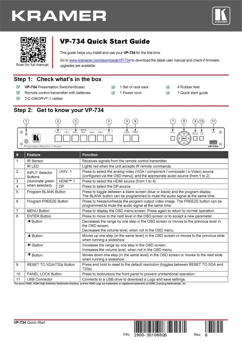
Step 2: Get to know your VS-21T
#
Feature
Function
1
IN 1 LED
Lights green when IN 1 is selected.
Upon power up, IN 1 is automatically switched to the output.
2
IN 2 LED
Lights green when IN 2 is selected.
3
ON LED
Lights green when the device receives power.
4
IN 1 RJ-45 Connector
Connect to an Ethernet source/HDBT transmitter.
5
IN 2 RJ-45 Connector
Connect to an Ethernet source/HDBT transmitter.
6
OUT RJ-45 Connector
Connect to an Ethernet sink/HDBT receiver.
7
REMOTE 3-pin Terminal Block Connector
Connect to the terminal block and then connect the wires to remote,
contact-closure switches for remote control.
8
5V DC Power Connector
5V DC connector for powering the unit.
Step 3: Mount VS-21T
Install VS-21T using one of the following methods:
•Attach the rubber feet and place the unit on a flat surface.
•Fasten a bracket (included) on each side of the unit and attach it to a flat surface
(see www.kramerav.com/downloads/VS-21T).
•Mount the unit in a rack using the recommended rack adapter
(see www.kramerav.com/product/VS-21T).
•Ensure that the environment (e.g., maximum ambient temperature &
air flow) is compatible for the device.
•Avoid uneven mechanical loading.
•Appropriate consideration of equipment nameplate ratings should be
used for avoiding overloading of the circuits.
•Reliable earthing of rack-mounted equipment should be maintained.
•Maximum mounting height for the device is 2 meters.
Step 4: Connect inputs and outputs
Always switch OFF the power on each device before connecting it to your VS-21T.
To achieve specified extension distances, use the recommended Kramer cables available at www.kramerav.com/product/VS-21T.
Using third-party cables may cause damage!
Step 5: Connect power
Connect the power cord to VS-21T and plug it into the mains electricity.
Safety Instructions (See www.kramerav.com for updated safety information)
Caution:
•For products with relay terminals and GPI\O ports, please refer to the permitted rating for an external connection, located next to the terminal or in the User Manual.
•There are no operator serviceable parts inside the unit.
Warning:
•Use only the power cord that is supplied with the unit.
•Disconnect the power and unplug the unit from the wall before installing.
Step 6: Operate VS-21T
Select an input (IN 1 or IN 2) via the contact closure remote control (also known as
push-to-make momentary contact). To do so, momentarily connect the required IN
pin on the REMOTE terminal block connector to the G (Ground) pin.
For example, to select IN 1 momentarily connect the IN 1 pin (red wire) to the G pin
(black wire). To select IN 2 momentarily connect the IN 2 pin (yellow wire) to the G
pin (black wire).
Technical Specifications
Input
2 HDBaseT Signal / Ethernet
On RJ-45 connectors
Output
1 HDBaseT Signal / Ethernet
On an RJ-45 connector
Range
N/A. (This device does not affect the range. The range depends on the sources and the receiver.)
Controls
Front Panel
IN 1, IN 2 and ON LED indicators
Rear Panel
IN 1and IN 2 remote contact closure buttons
Video
Max. Data Rate
8.91Gbps (2.97Gbps per graphic channel) pass−through
Max. Resolution
4K@60Hz (4:2:0) pass−through
Standards Compliance
HDCP 2.2
Power
Consumption
5V DC, 30mA
Source
5.2V DC, 4A
Environmental
Conditions
Operating Temperature
0° to +40°C (32° to 104°F)
Storage Temperature
-40° to +70°C (-40° to 158°F)
Humidity
10% to 90%, RHL non-condensing
Regulatory Compliance
Safety
CE, UL
Environmental
RoHs, WEEE
Enclosure
Size
Tool
Type
Aluminum
Cooling
Convection ventilation
General
Net Dimensions (W, D, H), each
12cm x 7.2cm x 2.4cm (4.7" x 2.8" x 0.94")
Shipping Dimensions (W, D, H)
15.7cm x 12cm x 8.7cm (6.2" x 4.7" x 3.4")
Net Weight, each
0.2kg (0.44bs) approx.
Shipping Weight
0.7 kg (1.5lbs) approx.
Accessories
Included
1 Power adapter, 1 power cord, 1 3-pin terminal block with wires
Specifications are subject to change without notice at www.kramerav.com

Other Kramer Switch manuals

Kramer VM-10FW User manual

Kramer

Kramer VM-10FW User manual

Kramer VP-311DVI User manual

Kramer

Kramer VP-311DVI User manual

Kramer 6502 User manual

Kramer

Kramer 6502 User manual

Kramer VP-28 User manual

Kramer

Kramer VP-28 User manual

Kramer VP-24 User manual

Kramer

Kramer VP-24 User manual

Kramer VS-21A User manual

Kramer

Kramer VS-21A User manual

Kramer VP3232 User manual

Kramer

Kramer VP3232 User manual

Kramer 6241HD User manual

Kramer

Kramer 6241HD User manual

Kramer TOOLS VP-222K User manual

Kramer

Kramer TOOLS VP-222K User manual

Kramer VS-21DT User manual

Kramer

Kramer VS-21DT User manual

Kramer PT201VGA User manual

Kramer

Kramer PT201VGA User manual

Kramer VP-725DSA User manual

Kramer

Kramer VP-725DSA User manual

Kramer VP-733 User manual

Kramer

Kramer VP-733 User manual

Kramer TOOLS VP-211K User manual

Kramer

Kramer TOOLS VP-211K User manual

Kramer VP-553xl User manual

Kramer

Kramer VP-553xl User manual

Kramer VP-438 User manual

Kramer

Kramer VP-438 User manual

Kramer VS-44HN User manual

Kramer

Kramer VS-44HN User manual

Kramer VS-21DTP User manual

Kramer

Kramer VS-21DTP User manual

Kramer VS-41DVI-R User manual

Kramer

Kramer VS-41DVI-R User manual

Kramer VS-201YC User manual

Kramer

Kramer VS-201YC User manual

Kramer DIP-31 User manual

Kramer

Kramer DIP-31 User manual

Kramer VP-214DS User manual

Kramer

Kramer VP-214DS User manual

Kramer VS-4x4FW User manual

Kramer

Kramer VS-4x4FW User manual

Kramer VS-1211 User manual

Kramer

Kramer VS-1211 User manual

Popular Switch manuals by other brands

Omron D4C - datasheet

Omron

Omron D4C - datasheet

Targus ACH227 user guide

Targus

Targus ACH227 user guide

ORiNG TGXPS-1080-M12-24V Series Quick installation guide

ORiNG

ORiNG TGXPS-1080-M12-24V Series Quick installation guide

NETGEAR FS726T - ProSafe Smart Switch operating instructions

NETGEAR

NETGEAR FS726T - ProSafe Smart Switch operating instructions

StarTech.com HB30A10AME quick start guide

StarTech.com

StarTech.com HB30A10AME quick start guide

Extron electronics PVT Series user guide

Extron electronics

Extron electronics PVT Series user guide

Perle IDS-409F quick start guide

Perle

Perle IDS-409F quick start guide

NETGEAR DS108 - Hub installation guide

NETGEAR

NETGEAR DS108 - Hub installation guide

SMC Corporation PF3W3 Series Operation manual

SMC Corporation

SMC Corporation PF3W3 Series Operation manual

Ascentic MH3-4K user manual

Ascentic

Ascentic MH3-4K user manual

Oase ProMax Garden Automatic Switch operating instructions

Oase

Oase ProMax Garden Automatic Switch operating instructions

Raritan CS16(R) user manual

Raritan

Raritan CS16(R) user manual

AMX DCP-MTX user manual

AMX

AMX DCP-MTX user manual

Edimax SP-1101W Quick installation guide

Edimax

Edimax SP-1101W Quick installation guide

Link electronics 860-XL162A Specification sheet

Link electronics

Link electronics 860-XL162A Specification sheet

Danfoss MP 54 installation guide

Danfoss

Danfoss MP 54 installation guide

ATEN VanCryst VS4818 quick start guide

ATEN

ATEN VanCryst VS4818 quick start guide

Ceragon FibeAir IP-20C user guide

Ceragon

Ceragon FibeAir IP-20C user guide

manuals.online logo
manuals.online logoBrands
  • About & Mission
  • Contact us
  • Privacy Policy
  • Terms and Conditions

Copyright 2025 Manuals.Online. All Rights Reserved.