Page 1.2 MEMS FIBER OPTIC SWITCH MODULE 40/42-855A
pickering
SECTION 1 - TECHNICAL SPECIFICATION
MEMS Fiber Optic Switch, 40/42-855A
pickeringtest.com
Specifications
Power Requirements - 40-855A
+3.3 V +5 V +12 V -12 V
150 mA 300 mA (typ 220 mA) 0 0
Power Requirements - 42-855A
+3.3 V +12 V
150 mA TBD
General Specification (All versions)
Fiber Switch Type:
Internal Fiber Type:
MEMS
SM 9/125
Wavelength:
Insertion loss:
Return loss (APC version):
Return loss (other versions):
Polarization dependent loss (PDL):
Repeatability:
Crosstalk:
Optical Input Power:
1240 to 1640 nm
0.8 dB Typ
60 dB Min
55 dB Min
0.05 dB Max
±0.01 dB Max
-60 dB Max
300 mW Max
Thermal Stability:
(-10 to 75 °C insertion loss variation)
0.2 dB Max
Expected Life: >>109 operations
Maximum Switching Time:
Cycle Rate:
1 ms
500/sec
Additional Specification (MM versions)
Fiber Switch Type:
Internal Fiber Type:
MEMS
MM 62.5/125
Wavelength:
Insertion loss:
Return loss:
Polarization dependent loss (PDL):
700 to 1700 nm
0.8 dB Typ
55 dB Min
0.05 dB Max
Connectors
40-855A - PXI bus via 32-bit P1/J1 backplane connector.
42-855A - PXIe bus via XJ3 and XJ4 backplane connectors.
Signals via front panel connectors, for connector positions
please refer to the operating manual:
• 40/42-855A-0x2 FC/APC connectors
• 40/42-855A-1x2 FC/PC connectors
• 40/42-855A-2x2 SC/PC connectors
• 40/42-855A-3x2 MU (mini SC) connectors
• 40/42-855A-4x2 LC connectors
• 40/42-855A-2x2-M SC connectors
• 40/42-855A-5x2-M ST connectors
• Interlock: 1 x 4-pin female 00 series connector*
(40/42-855A versions with hardware interlock option)
*Mating half supplied when hardware interlock option
ordered.
Other Connector Types
Pickering can manufacture fiber optic switch modules
with other connector types, please contact sales office for
further information.
Hardware Interlock
The 40/42-855A modules are available with an
optional hardware interlock. The interlock, when
activated, will return all optical switches to their
default unpowered state (assuming the switches
are fully functional) and also provide error
notification via the software interface. The interlock
feature can be daisy-chained between additional
hardware interlock enabled modules for example
to allow one signal to disable multiple cards.
For further details please refer to the Hardware
Interlock section within the user manual.
The hardware interlock feature is not available on
40/42-855A-4xx modules due to the size of the LC
connectors.
Note: LED indication is not available for modules
with the hardware interlock feature.
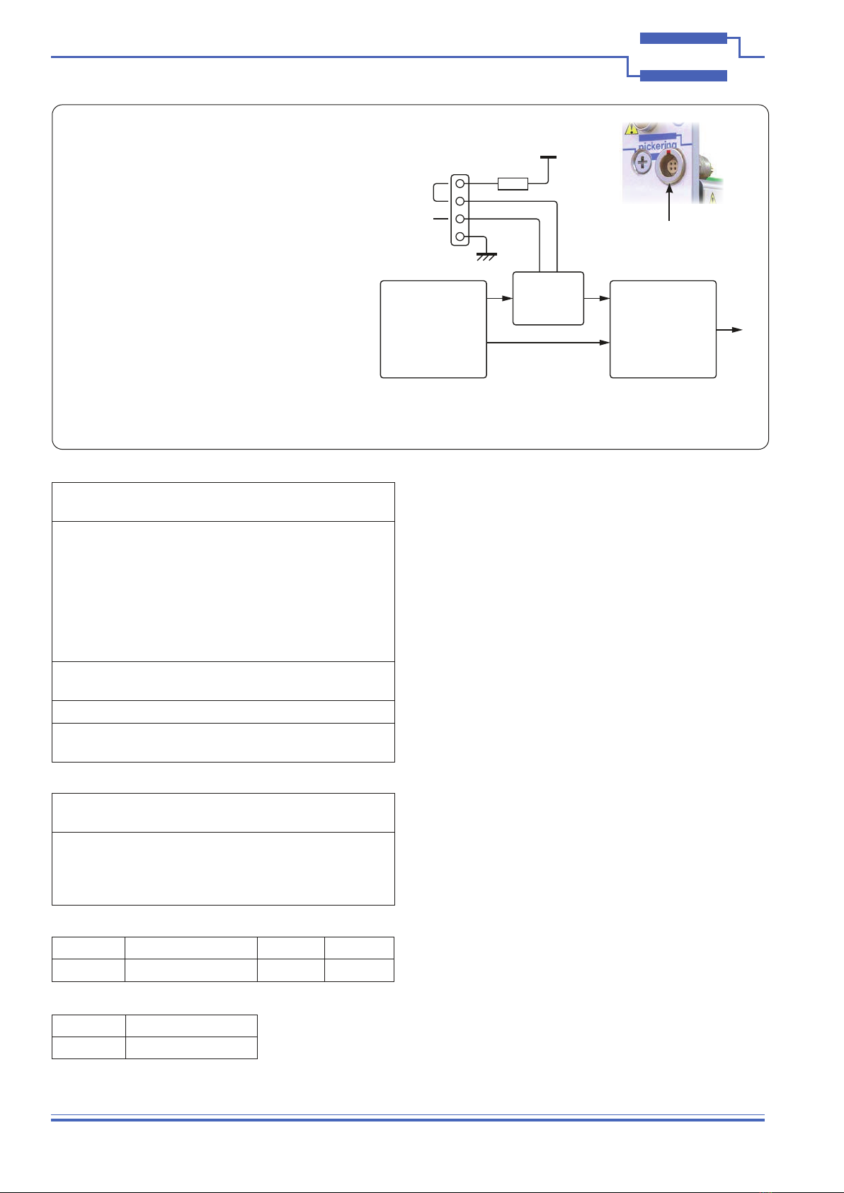
100 Ω
+3.3 V
GND
External
Wire Link
Front Panel
Connector
Interlock
Daisy-chain
Interlock
Detection
Circiuitry
Processor Relay Driver(s)
SPI Serial
Comms
Output Enable
SPI Serial
Comms
Output Enable
Drive
Outputs
To
Optical
Switches
Interlock Signal Routing Diagram for 40/42-855A
Versions With Hardware Interlock Option
Interlock Connector
Mechanical Characteristics
40-855A - 3 U PXI (CompactPCI card). Single or dual slot as
indicated in Product Order Codes.
42-855A - 3 U PXIe, compatible with PXIe hybrid slot. Single
or dual slot as indicated in Product Order Codes.
Module weight: <0.8 Kg typical.
3D models for all versions in a variety of popular file
formats are available on request.