Kramer KIT-400 User manual

Kramer Electronics Ltd.
KIT-400 –Contents
i
Contents
Introduction 1
Getting Started 1
Overview 2
Typical Applications 4
Defining KIT-400 4K Auto-Switcher/Scaler Kit 5
Defining KIT-400T 5
Defining KIT-400R 6
Mounting KIT-400 8
Connecting KIT-400 9
Connecting the Output to a Balanced/Unbalanced Stereo Audio Acceptor 10
Connecting to KIT-400 via RS-232 10
Connecting an Occupancy Sensor to the TOGL Pin 11
Wiring RJ-45 Connectors 11
Operating and Controlling KIT-400 12
Using Front Panel Buttons 12
Using Remote Control Switches 12
Setting KIT-400T DIP-switches 13
Tunneling RS-232 data between KIT-400T and KIT-400R 13
Using the OSD Menu on KIT-400R 16
Operating via Ethernet 25
Using Embedded Webpages 28
Browsing Webpages 28
Switching and adjusting Port Signals 30
Defining General settings 31
Configuring Network Settings 33
Defining Time and Date 35
Upgrading the Firmware 36
Setting Authentication 38
Defining Video and Audio Settings 40
Defining Receiver Settings 42
Configuring Device Automation 43
Operating via Room Automation Panel 46
Managing EDID 59
Viewing About Page 64
Upgrading Firmware 65
Upgrading KIT-400T 65
Upgrading KIT-400R 65
Technical Specifications 66
Default Communication Parameters 68
KIT-400R Output Resolution Support 68
Default EDID 68
Protocol 3000 75
Understanding Protocol 3000 75
Protocol 3000 Commands 76
Result and Error Codes 92

Kramer Electronics Ltd.
KIT-400 –Introduction
1
Introduction
Welcome to Kramer Electronics! Since 1981, Kramer Electronics has been providing a world
of unique, creative, and affordable solutions to the vast range of problems that confront the
video, audio, presentation, and broadcasting professional on a daily basis. In recent years, we
have redesigned and upgraded most of our line, making the best even better!
Getting Started
We recommend that you:
•Unpack the equipment carefully and save the original box and packaging materials for
possible future shipment.
•Review the contents of this user manual.
Go to www.kramerav.com/downloads/KIT-400 to check for up-to-date user manuals,
application programs, and to check if firmware upgrades are available (where appropriate).
Achieving Best Performance
•Use only good quality connection cables (we recommend Kramer high-performance,
high-resolution cables) to avoid interference, deterioration in signal quality due to poor
matching, and elevated noise levels (often associated with low quality cables).
•Do not secure the cables in tight bundles or roll the slack into tight coils.
•Avoid interference from neighboring electrical appliances that may adversely influence
signal quality.
•Position your Kramer KIT-400 away from moisture, excessive sunlight and dust.
Safety Instructions
Caution:
•This equipment is to be used only inside a building. It may only be connected to other
equipment that is installed inside a building.
•For products with relay terminals and GPI\O ports, please refer to the permitted rating
for an external connection, located next to the terminal or in the User Manual.
•There are no operator serviceable parts inside the unit.
Warning:
•Use only the power cord that is supplied with the unit.
•To ensure continuous risk protection, replace fuses only according to the rating
specified on the product label which is located on the bottom of the unit.

Kramer Electronics Ltd.
KIT-400 –Introduction
2
Recycling Kramer Products
The Waste Electrical and Electronic Equipment (WEEE) Directive 2002/96/EC aims to reduce
the amount of WEEE sent for disposal to landfill or incineration by requiring it to be collected
and recycled. To comply with the WEEE Directive, Kramer Electronics has made
arrangements with the European Advanced Recycling Network (EARN) and will cover any
costs of treatment, recycling and recovery of waste Kramer Electronics branded equipment on
arrival at the EARN facility. For details of Kramer’s recycling arrangements in your particular
country go to our recycling pages at www.kramerav.com/support/recycling.
Overview
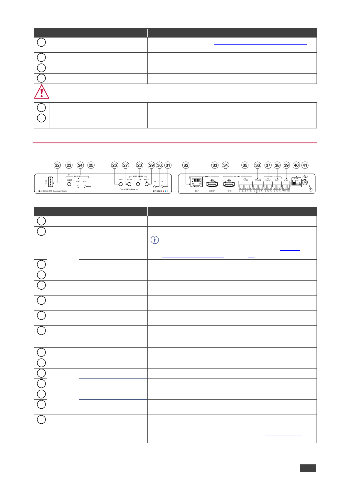
Congratulations on purchasing your Kramer KIT-400 4K Auto-Switcher/Scaler Kit.
KIT-400 is a high-performance auto-switcher/scaler kit for 4K HDMI™and VGA over long-
reach HDBaseT. The kit includes the KIT-400T 4K HDMI/PC Auto Switcher Transmitter and
the KIT-400R 4K HDBT/HDMI Receiver/Scaler. The KIT-400T transmitter converts the
user-selected input signal into the transmitted HDBaseT signal. The KIT-400R receiver
selects either its HDMI input or the received HDBaseT signal, and the selected signal is
output on HDMI after being up- or down-scaled to match the resolution of the HDMI monitor.
KIT-400 extends video signals to up to 40m (130ft) over CAT copper cables at up to
4K@60Hz (4:2:0) 24bpp video resolution and provides even further reach for lower HD video
resolutions.
KIT-400 provides exceptional quality, advanced and user-friendly operation, and flexible
control.
Exceptional Quality
•High-Performance Professional Switching and Scaling –Features input auto-switching,
constant sync on the output even if the input video signal is lost or interrupted, and a
built-in ProcAmp for convenient signal adjustment.
•HDMI Signal Extension –HDCP 1.4 / 2.2. 4K60, CEC, xvYCC color (on input).
Advanced and User-friendly Operation
•Automatic Room Control –Supports connection to an occupancy sensor and remote
switches, and includes a relay for driving room peripherals.
•Automatic Display Control –Supports CEC that enables automatically turning the display
on and off.
•Simple and Powerful Maestro Room Automation –Intuitive user interface enables you to
fully automate your meeting room elements. Configure lights, shades, devices and more
to be activated by an extensive range of triggers, including scheduling, input/output
connectivity, routing, and button pressing. By minimizing user intervention, Maestro
room automation saves meeting prep time and minimizes human error before
presentations.
•PoC (Power over Cable) –Power only one of the units. The other unit is powered via the
HDBaseT cable linking the receiver/transmitter pair.

Kramer Electronics Ltd.
KIT-400 –Introduction
3
•Easy Remote Device Control –Control devices connected to KIT-400 from the
user-friendly Kramer Aware interface on the KIT-400 embedded webpages, and access
the interface using the Kramer Aware app on a compatible Kramer touch panel.
•Convenient Unit Control and Configuration Options –Local control via front panel source
selection buttons, DIP-switches for audio configuration, and an OSD driven menu for
configuration of the receiver. Distance control via user-friendly embedded webpages via
Ethernet, Protocol 3000 API, RS-232 serial commands transmitted by a PC, touch
screen system or other serial controller and relay switches.
•Bidirectional RS-232 Extension –Serial interface data flows in both directions, allowing
data transmission and device control.
•Auto-scanning of inputs.
•Efficient power-saving features.
•Field Upgradable –Via its USB port (KIT-400T and KIT-400R), or via Ethernet
(KIT-400T).
•Easy, Cost-effective Maintenance –Local firmware upgrade via USB connector.
•Easy and Elegant Installation –Single cable connectivity for both HDBaseT signals and
power. Compact MegaTOOLS™ fan-less enclosure for dropped-ceiling mounting, or
side-by-side mounting of 2 units in a 1U rack space with the recommended rack adapter.
Flexible Connectivity
•Local Switching Control of 3 Local and 1 Remote Source –Select from 4 sources, each
with a dedicated selector button on the transmitter front panel, to output to an HDMI
display: 2 HDMI inputs and 1 VGA input, with dedicated audio jack, on the transmitter
side and an additional HDMI input on the receiver side.
•Audio De-embedding –Output the HDMI audio to a balanced stereo output on the
receiver side, and an unbalanced stereo output on the transmitter side.

Kramer Electronics Ltd.
KIT-400 –Introduction
4
Typical Applications
KIT-400 is ideal for the following typical applications:
•Classrooms and lecture halls.
•Meeting rooms.
•Training facilities.
•Collaborative classrooms.
•Any space where BYOD support is required.
Controlling your KIT-400
Control your KIT-400 via:
•Front panel SELECT buttons on KIT-400T.
•Navigation buttons to access the OSD menu on KIT-400R.
•RS-232 serial commands transmitted by a touch screen system, PC, or other serial.
•The Ethernet using built-in user-friendly webpages.
•Kramer Aware app from a compatible Kramer touch panel.

Kramer Electronics Ltd.
KIT-400 –Defining KIT-400 4K Auto-Switcher/Scaler Kit
5
Defining KIT-400 4K
Auto-Switcher/Scaler Kit
This section defines KIT-400T and KIT-400R.
Defining KIT-400T
Figure 1: KIT-400T 4K HDMI/PC Auto Switcher Transmitter
#
Feature
Function
IN 1
SELECT Button
Press to select the IN 1 input.
Lights red when the analog audio is selected; lights green
when the embedded audio is selected.
HDMI Connector
Connect to an HDMI source.
IN 2
SELECT Button
Press to select the IN 2 input.
Lights red when the analog audio is selected; lights green
when the embedded audio is selected.
HDMI Connector
Connect to an HDMI source.
IN 3
SELECT Button
Press to select the IN 3 input.
Lights red when the analog audio is selected; lights green
when embedded audio from embedded HDMI is selected.
15-pin HD Connector
Connect to a PC graphics source.
AUDIO IN 3.5mm Mini Jack
Connect to an unbalanced, stereo audio source (for example,
the audio output of the laptop).
IN 4 (REMOTE) Button
Press to select the inputs on KIT-400R:
•Button lights –HDMI INPUT on KIT-400R is selected as
the input.
•Button off –The selected input on KIT-400T is routed via
HDBT.
ON LED
Lights green when the device is powered.
AUDIO OUT 3.5mm Mini Jack
Connect to the unbalanced, stereo audio acceptor (for
example, active speakers).
LAN RJ-45 Connector
Connect to the LAN (Ethernet traffic or PC controller).
RS-232
CONTROL 3-pin
Terminal Block Connector
Connect to a serial controller or PC.
DATA 3-pin Terminal
Block Connector
Connect to a serial data source or acceptor.
Remote Contact-closure 5-pin
Terminal Block Connector
Connect to contact closure switches (by momentary contact
between the desired pin and GND pin) to select an input, and
to adjust the audio volume (up or down), see (see Using
Remote Control Switches on page 12).
RESET Button
Short press: sends a reset command to KIT-400R and then
reboots KIT-400T.
Long press: resets KIT-400R to its factory default parameters
and then resets KIT-400T to its factory default parameters.
1
2
3
4
5
6
7
8
9
10
11
12
13
14
15

Kramer Electronics Ltd.
KIT-400 –Defining KIT-400 4K Auto-Switcher/Scaler Kit
6
#
Feature
Function
SETUP 4-way DIP-switch
Set the device behavior (see Setting KIT-400T DIP-switches
on page 13).
SERVICE Mini USB Connector
Connect to a PC to perform a firmware upgrade.
HDBT OUT RJ-45 Connector
Connect to KIT-400R.
LINK LED
Lights blue when a link is established with the receiver.
Follow powering instructions in (see Connecting KIT-400 on page 9).
Failure to use PoC and power connector correctly may destroy the devices!
PoC (Power over Cable) Switch
Set the PoC switch to ON on both KIT-400T and KIT-400R.
12V DC Connector
Connect to the supplied power adapter, unless the power
adapter is connected to KIT-400R.
Defining KIT-400R
Figure 2: KIT-400R 4K HDBT/HDMI Receiver/Scaler
#
Feature
Function
PROG USB Connector
Connect to a USB stick to perform firmware upgrades.
INPUTS
SELECT Button
Press to select the input (HDBT or HDMI).
By default, the SELECT button is locked. You can unlock
it via the ADVANCED menu in the OSD (see Locking
KIT-400R Input Buttons on page 18).
HDBT LED
Lights blue when the HDBT input is selected.
HDMI LED
Lights blue when the HDMI input is selected.
MENU Button
Press to enter/exit the on-screen display (OSD) menu. Press
together with the –button to reset to 1080p.
ENTER Button
In OSD, press to choose the highlighted menu item. Press
together with the FREEZE/+ button to reset to XGA.
–
In OSD, press to move back through menus or decrement
parameter values.
FREEZE/+ Button
In OSD, press to move forward through menus or increment
parameter values. When not in OSD, press to freeze the
display.
LINK LED
Lights blue when a link is established with the transmitter.
ON LED
Lights green when device is powered.
INPUTS
HDBT RJ-45 Connector
Connect to KIT-400T.
HDMI Connector
Connect to an HDMI source.
OUTPUT
HDMI Connector
Connect to an HDMI acceptor.
AUDIO 5-pin Terminal
Block Connector
Connect to a balanced stereo audio acceptor.
REMOTE Contact-Closure 4-pin
Terminal Block Connector
Connect to contact closure switches, an occupancy sensor
and/or toggle switches (contact between the desired pin and
GND pin), to turn the display on or off. (See Using Remote
Control Switches on page 12).
16
17
18
19
20
21
22
23
24
25
26
27
28
29
30
31
32
33
34
35
36

Kramer Electronics Ltd.
KIT-400 –Defining KIT-400 4K Auto-Switcher/Scaler Kit
7
#
Feature
Function
RS-232
CONTROL 3-pin
Terminal Block
Connector
Connect to a serial controller or PC.
DATA 3-pin Terminal
Block Connector
Connect to a serial data source or acceptor.
RELAY 3-pin Terminal Block
Connector
Connections to the internal relay: Normally open (NO),
normally closed (NC), and common (C).
Connect to devices to be controlled by relay (for example, a
motorized projection screen).
Follow powering instructions in (see Connecting KIT-400 on page 9).
Failure to use PoC and power connector correctly may destroy the devices!
PoC (Power Over Cable) Switch
Set the PoC switch to ON on both KIT-400T and KIT-400R.
12V DC Connector
Connect to the supplied power adapter, unless the power
adapter is connected to KIT-400T.
37
38
39
40
41

Kramer Electronics Ltd.
KIT-400 –Mounting KIT-400
8
Mounting KIT-400
This section provides instructions for mounting KIT-400. Before installing, verify that the
environment is within the recommended range:
•Operation temperature –0to 40C (32 to 104F).
•Storage temperature –-40to +70C (-40 to +158F).
•Humidity –10% to 90%, RHL non-condensing.
Caution:
•Mount KIT-400 before connecting any cables or power.
Warning:
•Ensure that the environment (e.g., maximum ambient temperature & air flow) is
compatible for the device.
•Avoid uneven mechanical loading.
•Appropriate consideration of equipment nameplate ratings should be used for avoiding
overloading of the circuits.
•Reliable earthing of rack-mounted equipment should be maintained.
•Maximum mounting height for the device is 2 meters.
Mount KIT-400 in a rack:
•Use the recommended rack adapter
(see www.kramerav.com/product/KIT-400).
Mount KIT-400 on a surface using one of the following methods:
•Attach the rubber feet and place the unit on a flat surface.
•Fasten a bracket (included) on each side of the unit and attach it to
a flat surface. For more information go to
www.kramerav.com/downloads/KIT-400.

Kramer Electronics Ltd.
KIT-400 –Connecting KIT-400
9
Connecting KIT-400
Always switch off the power to each device before connecting it to your KIT-400. After
connecting your KIT-400, connect its power and then switch on the power to each device.
Figure 3: Connecting to the KIT-400
To connect KIT-400 as illustrated in the example in Figure 3:
1. Connect an HDMI source (for example, a Blu-ray player) to the IN 1 HDMI connector
on the KIT-400T front panel.
2. Connect an HDMI source (for example, a laptop) to the IN 2 HDMI connector on the
KIT-400T front panel.
3. Connect a computer graphics source (for example, a PC) to the IN 3 15-pin HD
connector and an unbalanced audio source (for example, the PC audio output) to the
AUDIO IN 3.5mm mini jack on the KIT-400T front panel.
4. Connect a control device to the LAN RJ-45 port on the KIT-400T rear panel.
5. Connect the HDBT OUT RJ-45 port on the KIT-400T to the HDBT INPUT RJ-45 port
on the KIT-400R.
6. Connect an HDMI source (for example, Kramer VIA GO) to the HDMI INPUT connector
on the KIT-400R.
7. Connect the HDMI OUTPUT connector on the KIT-400R to an HDMI acceptor (for
example, a display).
8. Connect the AUDIO OUTPUT 5-pin terminal block connector on the KIT-400R to a
balanced stereo audio source (for example, Kramer active speakers).
9. Connect the REMOTE TOGGLE switch to an occupancy sensor.
10.Connect the RELAY 3-pin terminal block connector to the room blinds.
11.Set POC switches on KIT-400T and KIT-400R to ON.
Failure to use PoC and power connector correctly may destroy the devices!
12.Connect the power adapter to one of the devices (KIT-400T or KIT-400R) and to the
mains electricity (not shown in Figure 3).
2
4
6
7
11
18
32
33
34
35
36
39
20
40

Kramer Electronics Ltd.
KIT-400 –Connecting KIT-400
10
Connecting the Output to a Balanced/Unbalanced
Stereo Audio Acceptor
The following are the pinouts for connecting the output to a balanced or unbalanced stereo
audio acceptor:
Figure 4: Connecting to a Balanced Stereo Audio
Acceptor
Figure 5: Connecting to an Unbalanced Stereo Audio
Acceptor
Connecting to KIT-400 via RS-232
You can connect to the KIT-400 via an RS-232 connection using, for example, a PC.
KIT-400 features two RS-232 3-pin terminal block connectors:
•CONTROL - To control KIT-400 (for example, via a connected PC).
•CONTROL –To control KIT-400R (for example, via a connected PC).
•DATA ( for KIT-400T and KIT-400R) –To tunnel RS-232 data between the
transmitter and the receiver, see Tunneling RS-232 data between KIT-400T and
KIT-400R on page 13, (for example, to control the projector via RS-232 using a
controller at the transmitter side).
Connect the RS-232 terminal block on the rear panel of the KIT-400 to a PC/controller, as
follows:
From the RS-232 9-pin D-sub serial port connect:
•Pin 2 to the TX pin on the KIT-400 RS-232 terminal
block
•Pin 3 to the RX pin on the KIT-400 RS-232 terminal
block
•Pin 5 to the G pin on the KIT-400 RS-232 terminal
block
RS-232 Device KIT-400
12
37
13
38

Kramer Electronics Ltd.
KIT-400 –Connecting KIT-400
11
Connecting an Occupancy Sensor to the TOGL Pin
The KIT-400R TOGL pin function is defined via the KIT-400R OSD menu (see Defining
the TOGGLE PIN on KIT-400R on page 22). By default, the display toggles on or off when
momentarily connected. By setting the Toggle function, you can set the pin for level-triggering
rather than edge-triggering (i.e., constant contact connection rather than momentary
connection), allowing, for example, connection to an occupancy sensor that triggers the
toggle commands.
Instead of a push-to-make switch, TOGGLE may be configured to operate with a standard
SPST switch or for TTL level detection (for example, to use with an occupancy sensor).
You can use an occupancy sensor to turn on the display and auto sync off to turn it off once it
is not used, as described in the following example:
•An occupancy sensor is connected to the TOGL pin.
•The TOGL pin is set to ON (see Defining the TOGGLE PIN on KIT-400R on page 22) so
that the display is turned on when the occupancy sensor detects the presence of people
in the room. (Set the sensor to short the TOGL pin to ground upon detecting occupancy).
•Auto SYNC OFF is set to Enable (see Setting Sleep Mode on page 20) so that when the
room is no longer in use, the display turns off 2 minutes after an input signal is no longer
detected.
You can also set the TOGL pin to OFF so that when the sensor detects no people in the room
the display turns off. (Set the sensor to short the TOGL pin to ground when occupancy is not
detected).
Wiring RJ-45 Connectors
This section defines the TP pinout, using a straight pin-to-pin cable with RJ-45 connectors.
For HDBT cables, it is recommended that the cable ground shielding be connected/soldered
to the connector shield.
EIA /TIA 568B
PIN
Wire Color
1
Orange / White
2
Orange
3
Green / White
4
Blue
5
Blue / White
6
Green
7
Brown / White
8
Brown
36

Kramer Electronics Ltd.
KIT-400 –Operating and Controlling KIT-400
12
Operating and Controlling KIT-400
Using Front Panel Buttons
Press the KIT-400T front panel buttons to select:
•The required input: IN 1 (HDMI) , IN 2 (HDMI) , IN 3 (VGA) or IN 4(REMOTE)
(HDMI on KIT-400R).
Press the KIT-400R front panel buttons to:
•Locally select the HDMI or HDBT inputs (when the SELECT button is not locked).
•Control device operation, using the MENU , ENTER (when in the OSD menu), +
and –,buttons (see Using the OSD Menu on KIT-400R on page 16).
•Freeze the image on the output, using FREEZE button.
•Reset to XGA, using ENTER and FREEZE+ buttons.
•Reset to 1080p, using MENU and –buttons.
Using Remote Control Switches
The following table describes the function of the remote contact closure switches on KIT-400T
and KIT-400R .
Pin Name
Function
KIT-400T
KIT-400R
KIT-400T
SELECT
Short press –Select the input.
Long press –Adjust the VGA phase shift.
IN 4
Select the IN 4 input on KIT-400R.
VOL UP
Increase the analog audio output level.
Short press –Increase volume by one step.
Long Press –Increase the volume from 0 to
100% in 10 seconds.
VOL DN
Decrease the analog audio output level.
Short press –Decrease volume by one step.
Long Press –Decrease the volume from 100% to
0 in 10 seconds.
KIT-400R
TOGL
For connection to an occupancy sensor, or to a
single ON/OFF switch.
Configurable via the OSD for connection to a
button which toggles between display on and
display off (instead of using two separate buttons
for on and off), or turning the display on and off
according to whether a switch is open or closed
(for example, when using an occupancy sensor).
See Defining the TOGGLE PIN on KIT-400R
on page 22.
OFF
Turn off the display.
ON
Turn on the display.
1
3
5
8
23
26
27
29
28
14
36

Kramer Electronics Ltd.
KIT-400 –Operating and Controlling KIT-400
13
Setting KIT-400T DIP-switches
A switch that is down is on; a switch that is up is off. By default, all the switches are set to off
(up).
DIP-switches 1 and 2 are both set to OFF (up).
Figure 6: KIT-400T SETUP DIP-Switches
After changing a DIP-switch you must power cycle the device to implement the change.
Audio Switching Selection
Use DIP-switches 3 and 4 to define the audio input source.
DIP-switch 3
DIP-switch 4
Audio Input Selection
Off (up)
Off (up)
Automatic –Priority selection: Embedded HDMI analog Audio In
(high to low priority).
Off (up)
On (down)
Automatic –Priority selection: Analog Audio In embedded HDMI
(high to low priority).
On (down)
Off (up)
Embedded HDMI.
On (down)
On (down)
Analog Audio In.
Tunneling RS-232 data between KIT-400T and
KIT-400R
KIT-400 tunnels RS-232 data between the transmitter and receiver in any of the following
ways:
•Controlling Via a Control System on page 14.
•Controlling a Sink Device Via the DATA Ports on page 15.
•Controlling Via Maestro on the Transmitter on page 15.

Kramer Electronics Ltd.
KIT-400 –Operating and Controlling KIT-400
14
Controlling Via a Control System
You can control the receiver and/or a connected sink device via a control system that is
connected to the CONTROL port on the KIT-400T.
Controlling the Receiver
To control the receiver via a control system at the transmitter, connect the control system to
the CONTROL RS-232 port and send a device protocol command via the TUNNEL-CTRL
command. For example, to open the relay contacts (RELAY-STATE 1,0), send the #TUNNEL-
CTRL 1,1,”RELAY-STATE 1,0”<CR> command from the control system, via HDBT to the
KIT-400R.
Figure 7: Controlling the Receiver via a Control System
Controlling a Sink Device Connected to the Receiver
For applications where the control system controls a device at the KIT-400R sink, connect the
control system to the CONTROL RS-232 port and send a device protocol command via
the TUNNEL-CTRL command.
For example, to turn the display off (DISPLAY OFF), send the #TUNNEL-CTRL
1,1,”TUNNEL-232 ‘DISPLAY OFF’9600”<CR> command from the control system, via HDBT
to the KIT-400R.
Figure 8: Controlling a Sink Device Connected to the Receiver
12
12

Kramer Electronics Ltd.
KIT-400 –Operating and Controlling KIT-400
15
Controlling a Sink Device Via the DATA Ports
Raw data can pass between the DATA ports on the transmitter and receiver ( for KIT-400T
and KIT-400R) directly to/from a controlled device and control system.
Figure 9: Controlling a Sink Device on the Receiver via the Data Ports
Controlling Via Maestro on the Transmitter
You can control the receiver and/or a connected sink device via the KIT-400T Kramer
Maestro.
Controlling the Receiver
To control the receiver via Maestro at the transmitter, send a command via the RS232_HDBT
port in Maestro. For example, to open the relay contacts (RELAY-STATE 1,0), send the
RELAY-STATE 1,0 command from Maestro, via HDBT to the KIT-400R.
Figure 10: Controlling the Receiver via Maestro
13
38

Kramer Electronics Ltd.
KIT-400 –Operating and Controlling KIT-400
16
Controlling a Sink Device Connected to the Receiver
You can control a sink device via KIT-400T Maestro. To control the sink device via Maestro at
the transmitter, send a command via the RS232_HDBT port in Maestro.
For example, to turn the display off (DISPLAY OFF), send the #TUNNEL-CTRL
1,1,”TUNNEL-232 ‘DISPLAY OFF’9600”<CR> command from Maestro, via HDBT to the
KIT-400R.
Figure 11: Controlling a Sink Device on the Receiver via Maestro
Using the OSD Menu on KIT-400R
KIT-400R enables controlling and defining the device parameters via the OSD, using the front
panel MENU buttons.
To enter and use the OSD menu buttons:
1. Press MENU.
2. Press:
▪ENTER to accept changes and to change the menu settings.
▪Arrow buttons to move through the OSD menu, which is displayed on the video
output.
▪EXIT to exit the menu.

Kramer Electronics Ltd.
KIT-400 –Operating and Controlling KIT-400
17
The default OSD timeout is set to 10 seconds.
Use the OSD menu to perform the following operations:
•Adjusting Image Parameters on page 17.
•Selecting an Input Signal on page 18.
•Setting Output Parameters on page 18.
•Setting Audio Parameters on page 19.
•Setting OSD Parameters on page 19.
•Setting HDCP on page 20.
•Setting Sleep Mode on page 20.
•Setting Switching Mode on page 21.
•Setting FREEZE Button Functionality on page 21.
•Managing EDID via OSD on page 21.
•Defining the TOGGLE PIN on KIT-400R on page 22.
•Manually Switching Relay on page 23.
•Defining CEC on page 23.
•Defining Power-up State on page 24.
•Viewing Device Information on page 24.
•Performing a Reset on page 24.
Adjusting Image Parameters
KIT-400R enables adjusting the image parameters such as contrast, brightness and so on.
To adjust the image parameters:
1. On the front panel press MENU. The menu appears.
2. Click Picture and define the image parameters according to the information in the
following table:
Menu Item
Function
Contrast
Set the contrast.
Brightness
Set the brightness.
Finetune
Video
HUE –set the color hue.
SATURATION –set the color saturation.
SHARPNESS –set the sharpness of the picture.
NR (Noise Reduction) –select the noise reduction filter: Off
(default), Low, Middle or High.
Color
Set the Red, Green and Blue shades.
Image parameters are adjusted.

Kramer Electronics Ltd.
KIT-400 –Operating and Controlling KIT-400
18
Selecting an Input Signal
Select the KIT-400R input source via the OSD menu.
To set the input source:
1. On the front panel press MENU. The menu appears.
2. Click INPUT and select the SOURCE
3. Press ENTER and select HDMI or HDBT.
An input signal is selected.
Locking KIT-400R Input Buttons
KIT-400R enables locking the input select buttons.
To set the input source:
1. On the front panel press MENU. The menu appears.
2. Click INPUT and select INPUT BUTTON LOCK.
3. Press ENTER and select ON or OFF.
Input select buttons are locked.
Setting Output Parameters
KIT-400R enables setting output parameters such as the size of the image and output
resolution via the OSD MENU buttons.
To set the output parameters:
1. On the front panel press MENU. The menu appears.
2. Click OUTPUT and define the output parameters according to the information in the
following table:
Menu Item
Function
Size
Set the size of the image: Over Scan, Full, Best Fit (default), Pan Scan, Letter Box, Under
2, Under 1, Follow In.
Resolution
Select the output resolution (default, Native HDMI):
640x480 @60Hz
1600x1200 @60Hz
3440x1440 @30Hz
1920x1080P @50Hz
800x600 @60Hz
1680x1050 @60Hz
3440x1440 @60Hz
1920x1080P @60Hz
1024x768 @60Hz
1920x1200 @60Hz RB
720x480P @60Hz
2560x1080P @50Hz
1280x768 @60Hz
2560x1600 @60Hz RB
720x576P @50Hz
2560x1080P @60Hz
1280x800 @60Hz
1920x1080 @60Hz
1280x720P @50Hz
3840x2160P @24Hz
1280x1024 @60Hz
1280x720 @60Hz
1280x720P @60Hz
3840x2160P @25Hz
1360x768 @60Hz
2048x1080 @50Hz
1920x1080P @24Hz
3840x2160P @30Hz
1400x1050 @60Hz
2048x1080 @60Hz
1920x1080P @25Hz
3840x2160P @50Hz
1440x900 @60Hz
2560x1440 @60Hz RB
1920x1080P @30Hz
3840x2160P @60Hz
Output parameters are defined.
Other manuals for KIT-400
2
This manual suits for next models
2
Table of contents
Other Kramer Switch manuals

Kramer
Kramer VP-731 User manual

Kramer
Kramer VS-211UHD User manual

Kramer
Kramer VP-440 User manual

Kramer
Kramer VS-421 User manual

Kramer
Kramer VP-720DS User manual

Kramer
Kramer VS-211H User manual

Kramer
Kramer VP-732 User manual

Kramer
Kramer 4x1V User manual

Kramer
Kramer VS-81ETH User manual

Kramer
Kramer VP-440 User manual

Kramer
Kramer VS-120 User manual

Kramer
Kramer SP-14 User manual

Kramer
Kramer VM-22H User manual

Kramer
Kramer VS-41HC User manual

Kramer
Kramer VP-719x1 User manual

Kramer
Kramer ProScale VP-728 User manual

Kramer
Kramer 6241N User manual

Kramer
Kramer VS-4x4FW User manual

Kramer
Kramer VP-443 User manual

Kramer
Kramer VP-720DS User manual