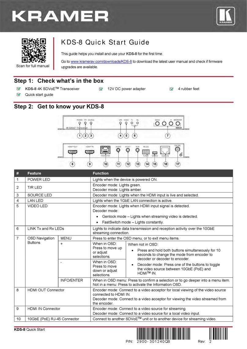
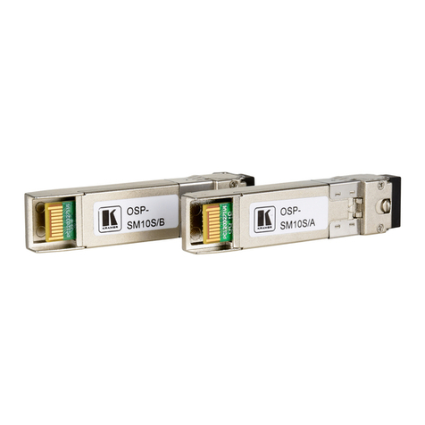
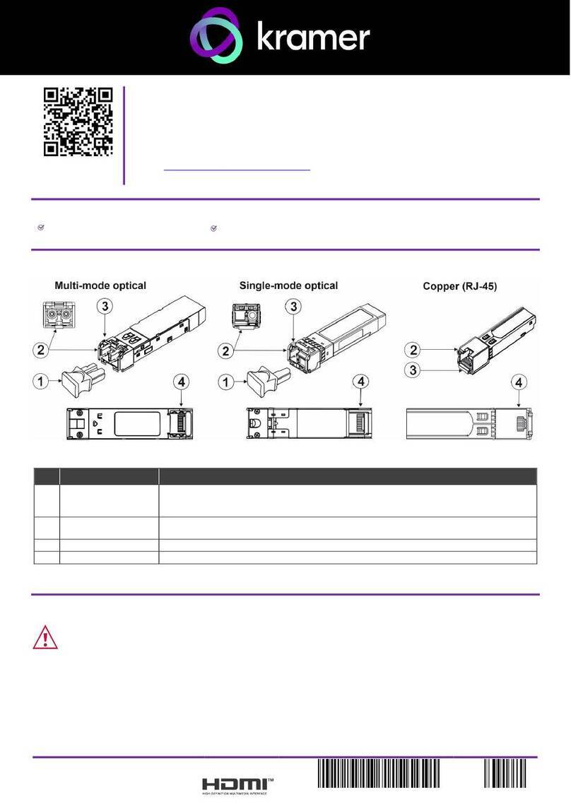
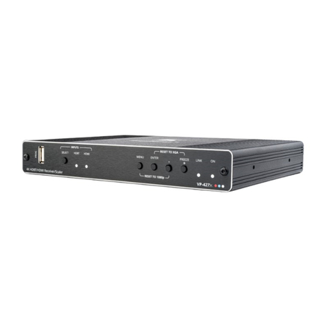
Kramer KDS-8-MNGR User manual

Kramer Electronics Ltd.
KDS-8-MNGR –Contents
i
Contents
Introduction 1
Getting Started 1
Overview 3
System Requirements 3
Typical Applications 4
Defining KDS-8-MNGR 5
Front and Back Panel 5
Connecting KDS-8-MNGR 7
RS-232 Pinout andDefaults 8
Operating via Ethernet 8
Using Embedded Web Pages 11
Discovering IP Address 13
Monitoring and Controlling Decoders and Encoders 14
Configuring the System 30
Configuring System Settings 33
Configuring Transmitters 45
Configuring Receivers 47
Defining Output Resolution 49
Configuring Video Walls 50
Configuring Multiviews 51
Technical Specifications 54
Default Communication Parameters 55
Video Specifications 55
Acronyms 57
Telnet Control 58
RS-232 and TelnetCommands 58

Kramer Electronics Ltd.
KDS-8-MNGR –Introduction
1
Introduction
Welcome to Kramer Electronics! Since 1981, Kramer Electronics has been providing a world
of unique, creative, and affordable solutions to the vast range of problems that confront the
video, audio, presentation, and broadcasting professional on a daily basis. In recent years, we
have redesigned and upgraded most of our line, making the best even better!
In this user manual, KDS-8 refers also to KDS-8F.
Getting Started
We recommend that you:
•Unpack the equipment carefully and save the original box and packaging materials for
possible future shipment.
•Review the contents of this user manual.
Go to www.kramerav.com/downloads/KDS-8-MNGR to check for up-to-date user manuals,
application programs, and to check if firmware upgrades are available (where appropriate).
Achieving Best Performance
•Use only good quality connection cables (we recommend Kramer high-performance,
high-resolution cables) to avoid interference, deterioration in signal quality due to poor
matching, and elevated noise levels (often associated with low quality cables).
•Do not secure the cables in tight bundles or roll the slack into tight coils.
•Avoid interference from neighboring electrical appliances that may adversely influence
signal quality.
•Position your Kramer KDS-8-MNGR away from moisture, excessive sunlight and dust.
Safety Instructions
Caution:
•This equipment is to be used only inside a building. It may only be connected to other
equipment that is installed inside a building.
•For products with relay terminals and GPI\O ports, please refer to the permitted rating
for an external connection, located next to the terminal or in the User Manual.
•There are no operator serviceable parts inside the unit.
Warning:
•Use only the power cord that is supplied with the unit.
•To ensure continuous risk protection, replace fuses only according to the rating
specified on the product label which is located on the bottom of the unit.

Kramer Electronics Ltd.
KDS-8-MNGR –Introduction
2
Recycling Kramer Products
The Waste Electrical and Electronic Equipment (WEEE) Directive 2002/96/EC aims to reduce
the amount of WEEE sent for disposal to landfill or incineration by requiring it to be collected
and recycled. To comply with the WEEE Directive, Kramer Electronics has made
arrangements with the European Advanced Recycling Network (EARN) and will cover any
costs of treatment, recycling and recovery of waste Kramer Electronics branded equipment on
arrival at the EARN facility. For details of Kramer’s recycling arrangements in your particular
country go to our recycling pages at www.kramerav.com/support/recycling.

Kramer Electronics Ltd.
KDS-8-MNGR –Introduction
3
Overview
Congratulations on purcwhasing your Kramer KDS-8-MNGR SDVoE Manager (Software
Defined Video over Ethernet Manager). KDS-8-MNGR Manager is the solution for
configuration and management of KDS-8 and KDS-8F deployments within the same network.
Just install the unit into the same local network as the extenders (encoders and decoders) to
easily define and configure channel routing selections (including video, audio, and a variety of
control interface types) using the embedded web pages. Without the use of this centralized
control unit, each encoder/decoder pair would only function in a point-to-point capacity.
Additionally, this unit supports controlling and configuring the matrix, video wall, and
multiviewer modes of connected KDS−8 devices. The settings of all connected
encoder/decoder units, including IP configuration, compatibility settings, and extender status
are clearly displayed and easily managed in the embedded web pages.
A trigger input interface is also provided to allow the easy addition of a Kramer Control remote
keypad, or other trigger-supporting products, which can beinstalled within a podium or table in
a conference room or classroom. Thisinterface can allow the user to activate stored macros
with the simple press ofa button. Standard control is available via the embedded web pages
(remote or local),RS-232, Telnet and IR Remote.
KDS-8-MNGR provides exceptional quality and user-friendly operation:
•Centralized Management –Manage and configure multiple compatible KDS-8 devices
through a single web interface. Control the independent routing of video, audio and
control signals. Configure matrix, video wall, and multiviewer modes.
•Customizable –Create macros to further streamline and customize operation of the
connected devices.
•Status at-a-Glance –Displays the status of all connected Transmitters and Receivers,
including IP addresses, channel selections, and more.
•Serial Control –Generates serial commands to directly control an external
serial-controlled device.
•Flexible Power –Can be powered by Ethernet switches supporting the IEEE 802.3af
2003 PoE standard (optional).
•Convenient Control Options –Standard control is available via embedded web pages
(remote or local), RS-232, and Telnet.
System Requirements
Operating the KDS-8-MNGR, requires an active network connection from a switch or router
for controlof compatible AV over IPdevices.

Kramer Electronics Ltd.
KDS-8-MNGR –Introduction
4
Typical Applications
KDS-8-MNGR is ideal for the following typical applications:
•Video/TV wall display and control.
•Security surveillance and control.
•Commercial advertising, display and control.
•Home theaters with smart home controls.
•Retail sales and demonstration.

Kramer Electronics Ltd.
KDS-8-MNGR –Defining KDS-8-MNGR
5
Defining KDS-8-MNGR
Front and Back Panel
Figure 1: KDS-8-MNGR SDVoE Manager Front Panel
#
Feature
Function
POWER LED
Lights when the device receives power.
IR Window
N/A
Figure 2: KDS-8-MNGR SDVoE Manager Rear Panel
#
Feature
Function
IR EXT Port
For future use.
CONTROL 5-pin
Terminal Block
For future use.
RS-232 3-pin Terminal
Block
Connect to a PC, laptop or other serial control device with a 3-pin adapter
cable to control the unit via RS-232.
TRIGGER IN 10-pin
Terminal Block
Connect to the Trigger Control Keypad (OPTIONAL) or any device with
trigger switch functionality such as window security alarms, motion
detectors, door switches, etc. Each of the 8 trigger inputs will activate the
associated macro (1~8) when triggered.
A minimum of 5V DC is required to activate each trigger.
HDMI™OUT Port
Connect to a standard HDMI display to view the unit current status
information and access the embedded web pages directly without a PC.
HDMI output is locked to a resolution of 1080p@60Hz.
USB Port
Connect a USB mouse and keyboard to control the unit’s embedded web
pages that are displayed on the HDMI output port. Firmware update via
USB is also supported.
Specialized USB control devices, such as a touch panel, should be
connected before the unit is powered on.
LAN 2 Port
Connect directly, or through a network switch, to your PC/ laptop to control
the unit via embedded web pages/Telnet.
1
2
3
4
5
6
7
8
9

Kramer Electronics Ltd.
KDS-8-MNGR –Defining KDS-8-MNGR
6
#
Feature
Function
LAN 1(POE) Port
Connect to the SDVoE units’ 10G Network through dedicated network
switch, to enable detection and control over those units.
If the connected network switch supports the IEEE 802.3af 2003 PoE
(Power over Ethernet) standard, KDS-8-MNGR can optionally be
powered directly via this Ethernet port.
FACTORY RESET
Press and hold for 3 seconds to reset the unit to its factory defaults,
including Ethernet settings.
While the reset is in process, the front panel LEDs flash. Once the reset
is complete, the unit returns to normal operation.
5V DC Port
Plug the 5V DC power adapter into the unit and connect it to an AC wall
outlet for power. (Optional, not required if the unit is powered via PoE).
10
11
12

Kramer Electronics Ltd.
KDS-8-MNGR –Connecting KDS-8-MNGR
7
Connecting KDS-8-MNGR
Always switch off the power to each KDS-8 device before connecting it to your
KDS-8-MNGR. After connecting your KDS-8-MNGR, connect its power and then switch on
the power to each device.
Figure 3: Connecting to the KDS-8-MNGR
To connect KDS-8-MNGR as illustrated in the above example:
1. Connect an HDMI acceptor to the HDMI OUT connector .
2. Connect the USB port to a USB Hub that is connected to a keyboard and mouse.
3. Connect Ethernet LAN 2 RJ-45 connector to a 1G Network switch that is connected
to a laptop.
Alternatively, you can connect LAN 2 directly to a laptop.
4. Connect Ethernet LAN 1 (PoE) RJ-45 Connector to a 10G Network switch that is
connected to KDS-8 (or KDS-8F) encoders and decoders.
5. Connect the 5V DC connector power adapter to the device and the mains electricity.
If the unit is powered via PoE (PD) there is no need to connect the power
adapter.
7
8
10
12
9

Kramer Electronics Ltd.
KDS-8-MNGR –Connecting KDS-8-MNGR
8
RS-232 Pinout and Defaults
Serial Port Default Settings
Unit Control
Serial Output
Baud Rate
19200
3-pin Terminal Block
5-pin Terminal Block
Data Bits
8
Parity Bits
None
Stop Bits
1
Flow Control
None
Operating via Ethernet
You can connect to KDS-8-MNGR via Ethernet using either of the following methods:
•Directly to the PC using a crossover cable (see Connecting Ethernet Port Directly to a
PC on page 8).
•Via a network hub, switch, or router, using a straight-through cable (see Connecting
Ethernet Port via a Network Hub on page 10).
If you want to connect via a router and your IT system is based on IPv6, speak to your IT
department for specific installation instructions.
Connecting Ethernet Port Directly to a PC
You can connect the Ethernet port of KDS-8-MNGR directly to the Ethernet port on your PC
using a crossover cable with RJ-45 connectors.
This type of connection is recommended for identifying KDS-8-MNGR with the factory
configured default fallback IP address.
After connecting KDS-8-MNGR to the Ethernet port, configure your PC as follows:
1. Click Start > Control Panel > Network and Sharing Center.
2. Click Change Adapter Settings.
3. Highlight the network adapter you want to use to connect to the device and click Change
settings of this connection.
The Local Area Connection Properties window for the selected network adapter appears
as shown in Figure 4.

Kramer Electronics Ltd.
KDS-8-MNGR –Connecting KDS-8-MNGR
9
Figure 4: Local Area Connection Properties Window
4. Highlight either Internet Protocol Version 6 (TCP/IPv6) or Internet Protocol Version 4
(TCP/IPv4) depending on the requirements of your IT system.
5. Click Properties.
The Internet Protocol Properties window relevant to your IT system appears as shown in
Figure 5 or Figure 6.
Figure 5: Internet Protocol Version 4 Properties Window

Kramer Electronics Ltd.
KDS-8-MNGR –Connecting KDS-8-MNGR
10
Figure 6: Internet Protocol Version 6 Properties Window
6. Select Use the following IP Address for static IP addressing and fill in the details as
shown in Figure 7.
For TCP/IPv4 you can use any IP address in the range 192.168.1.1 to 192.168.1.255
(excluding 192.168.1.39).
Figure 7: Internet Protocol Properties Window
7. Click OK.
8. Click Close.
Connecting Ethernet Port via a Network Hub or Switch
You can connect the Ethernet port of KDS-8-MNGR to the Ethernet port on a network hub or
using a straight-through cable with RJ-45 connectors.
Configuring Ethernet Port
You can set the Ethernet parameters via the embedded Web pages.

Kramer Electronics Ltd.
KDS-8-MNGR –Using Embedded Web Pages
11
Using Embedded Web Pages
KDS-8-MNGR can be operated and controlled remotely using the embedded Web pages. The
Web pages are accessed using a Web browser and an Ethernet connection. By default,
KDS-8-MNGR is set to DHCP.
Before attempting to connect:
•If required, discover the device IP Address (see Discovering IP Address on page 13).
•Perform the procedures in Operating via Ethernet on page 8.
•Ensure that your browser is supported.
The following operating systems and Web browsers are supported:
Operating Systems
Browser
Windows 10
Chrome (Recommended)
Firefox
Mac
Safari
iOS
Safari
Android
Chrome
Some features might not be supported by some mobile device operating systems.
KDS-8-MNGR enables performing the following:
•Discovering IP Address on page 13.
•Monitoring and Controlling Decoders and Encoders on page 14.
•Configuring the System on page 30.
•Configuring System Settings on page 33.
•Configuring Transmitters on page 45.
•Configuring Receivers on page 47.
•Defining Output Resolution on page 49.
•Configuring Video Walls on page 50.
•Configuring Multiviews on page 51.

Kramer Electronics Ltd.
KDS-8-MNGR –Using Embedded Web Pages
12
To use the browser:
1. Open your Internet browser.
2. Type the IP number of the device, or its hostname, in the Address bar of your browser.
For example,:
The device operation page appears.
After connecting to the embedded pages address in a web browser, theembedded pages
load and display the System tab.
To Access the embedded web pages:
1. Click Login to open the authentication window.
2. Enter the appropriate User Name and Password (admin) and click Enter.
If a keyboard is not available, such as when using a touch screen, an on-screen
keyboard can be activated by clicking on the keyboard icon ( ).
The default user name and password isadmin.
Figure 8: Accessing the Embedded Web Pages

Kramer Electronics Ltd.
KDS-8-MNGR –Using Embedded Web Pages
13
Once you are logged-in, the menu tabs appear to the left of each page.
Figure 9: Menu Tabs
To logout:
1. In the System tab click Logout.
When not logged in, only the Monitor & Control and Systemtabs are available.
Discovering IP Address
You can discover the IP address either by connecting and then sending RS-232 commands
via the KDS-8-MNGR RS-232 port (see RS-232 and Telnet Commands on page 58), or via
the HDMI output.
To discover or change the IP address via HDMI output:
1. Connect the KDS-8-MNGR HDMI output to a display. The System tab in the offline
embedded web pages appears (only Monitor & Control and System tabs are displayed
offline).
2. View the IP address or change it as follows:
a. Connect a mouse to the USB port on the rear panel.
b. Click to open a keyboard on-screen to enter text.
c. Click Login. The Login window appears.
Figure 10: Login Window

Kramer Electronics Ltd.
KDS-8-MNGR –Using Embedded Web Pages
14
d. Click mouse in User Name text box. On-screen keyboard opens.
e. Enter the User Name (admin, by default).
f. Move cursor to Password text box.
g. Enter the Password (admin, by-default).
h. Click Enter.
3. Change Network settings as desired.
Discovered IP address can be used to access embedded web pages online.
Monitoring and Controlling Decoders and Encoders
The Monitor & Control tab provides easy to use drag-and-drop control over all basicrouting
functions of the KDS-8 encoders and decoders that have been detectedwithin the local
network and enables performing the following actions:
•Routing Video on page 15.
•Routing a Video Wall on page 17.
•Routing a Multi-viewer on page 18.
•Routing HDMI Audio on page 19.
•Routing Analog Audio on page 22.
•Pairing USB Hosts and Devices on page 24.
•Routing IR Signals on page 26.
•Routing RS-232 Signals on page 27.
•Activating a Macro on page 29.
In all the sections (except for the Routing Video section), transmitters (encoders) are
represented by the source icon ( ) and receivers (decoders) are represented by the display
icon ( ). Each of this tab’s sections control the routing of a different type of interface of
KDS-8 and KDS-8F.
Units that were previously a part of the system, but are notcurrently detected will still be
displayed, however they will have a disconnected icon ( ) and cannot be used for routing.

Kramer Electronics Ltd.
KDS-8-MNGR –Using Embedded Web Pages
15
Routing Video
Drag and drop detected encoders and decoders to control video routing in the system.
The Video page includes two main areas. The:
•Video Transmitter area, which includes drag-and-drop depiction buttons for all the
encoders that are detected by the system, and a multi-option stopbutton to stop video
transmission.
•Video Receiver area, which includes drag-and-drop depiction buttons forall the
decoders that are detected by the system, and a Stop button to stop one or all output
streams from beingdisplayed.
Each encoderand decoder box is depicted as a small-sized, low-framerate, video thumbnail
indicating which video is currentlyactive, or can be represented as follows to indicate that:
The encoder is in the video wall mode.
The encoder is in the Multiviewer mode.
The encoder current input has no live source connected.
The decoder does not have an active display connected.
The encoder/decoder does not support the video thumbnail feature.
The encoders’ source streams are collectively exceed the 10Gbps bandwidth
limitation.
The encoder/decoder is offline or currently not detected by KDS-8-MNGR.
KDS-8-MNGR features automatic bandwidth reduction if the total source streaming exceeds
10Gbps. In case this happens, we recommend that you reduce the source resolution, frame
rate or bit depth to maintain stable video quality on the display.
The Video page enables performing the following actions:
•Streaming an HDMI Audio Source to a Single Decoder on page 20.
•Streaming an HDMI Audio Source to Multiple Decoders on page 21.
•Stopping an HDMI Audio Source Stream on page 21.
•Stopping an HDMI Audio Display Stream on page 21.

Kramer Electronics Ltd.
KDS-8-MNGR –Using Embedded Web Pages
16
Streaming a Source to a Single Decoder
Toroute a source (on a detected encoder) to a display on an encoder:
1. In the Menu tabs, select Monitor & Control. The Video page appears.
Figure 11: Monitor & Control Tab –Video Page
2. Click and drag a source button in the transmitter area to the preferreddisplay in the
receiver area.
3. Release the mouse button.
The routed source name appears below the display name.
The selected source and routed displays change their color.
You can also drag and drop display decoders to an encoder source on the transmitter side to
activate a new streaming route.
The source on the encoder is streamed to the decoder.
Streaming a Source to Multiple Decoders
Toroute a source (on a detected encoder) to multiple encoders:
1. In the Menu tabs, select Monitor & Control. The Video page appears.
2. Click and drag a source button in the transmitter area to a predefined Video group or an
All button in the receiver area.
3. Release the mouse button.
The routed source name appears below the group name.
The source on the encoder is streamed to multiple decoders.

Kramer Electronics Ltd.
KDS-8-MNGR –Using Embedded Web Pages
17
Stopping a Video Source Stream
You may need to stop one or all the video streams comingfrom a source.
To stop a video source stream:
1. In the Menu tabs, select Monitor & Control. The Video page appears.
2. Click (Stop selection button) at the lower part of the transmitter area and cycle to the
required option:
▪All Stop stops all stream types from the selected source.
▪Native Stop stops only the full resolution primary video stream.
▪Multiview Stop stops only the secondary video stream used by multiviewer layouts.
3. Click and drag the source to the selected Stop button. Streaming from that source stops.
To stop a stream type from ALL video streams simultaneously, drag Alldown to the
All Stop button.
Source/s streaming has stopped.
Stopping a Video Display Stream
To stop a video display stream:
1. In the Menu tabs, select Monitor & Control. The Video page appears.
2. Click and drag the display to the Stop button.
3. Release the mouse. Streaming to that display stops.
Drag Allbutton down to the Stop button to stop all streaming.
Display streaming has stopped.
Routing a Video Wall
Drag and drop detected encoder sources and decoder displays to control predefined video
wall routing in the system. Go to Configuring Video Walls on page 50 to define a video wall
group.
The Video Wall section includes three main areas. The:
•Group area, which includes all the currently defined video wall groups Click a group icon
to display a simplified
graphical representation of the video wall on the video wall view
on the right side of thepage. For example, Video Wall 1 group shows as Group: Video
Wall 1 on the rightside of the Video wall section.
•Transmitter area, which includes all the available decoders.
•Video wall view area, representing the selected video wall.

Kramer Electronics Ltd.
KDS-8-MNGR –Using Embedded Web Pages
18
Toassign a source to a video wall group:
1. In the Menu tabs, select Monitor & Control. The Video section appears.
2. Click Video wall. The Video Wall section appears.
Figure 12: Monitor & Control Tab –Video Wall Page
3. Drag a source from the Transmitter area to the required video wall group.
The source on the encoder is streamed to the Video Wall.
Dragging a source to an inactive video wall group, automatically activates all ofthat video wall
displays.
Routing a Multi-viewer
Set the streaming in a multi-viewer by dragging and dropping the Multiview preset to an
available decoder display and also by dragging and dropping a decoder source over to
Multiview windows.
Before routing inputs to Multiview windows, you need to define a Multiview preset
(see Configuring Multiviews on page 51).
The Multiview page includes four main areas. The:
•Preset area, which includes all currently defined multiview presets.
•Receiver area, which includes all the decoderdisplays that availableto display the
muliview preset.
•Multiviewer view area, which shows a simplified graphical representation of the
currently selected multiview preset. An active preset appears has green windows that
show a faded video thumbnail ofthe source that is currently selected.
•Transmitter area, which includes all the encoder sources. Unavailable sources are
displayed in red.
Other manuals for KDS-8-MNGR
1
Table of contents
Other Kramer Transceiver manuals

Kramer
Kramer KDS-8 User manual

Kramer
Kramer 621R User manual

Kramer
Kramer SFP-1G User manual

Kramer
Kramer KW-14T User manual

Kramer
Kramer TP-43 User manual

Kramer
Kramer KDS-8 User manual

Kramer
Kramer OSP-SM10S User manual

Kramer
Kramer KDS-8F User manual

Kramer
Kramer TP-576 User manual

Kramer
Kramer VP-427X User manual
Popular Transceiver manuals by other brands

Standard
Standard C168 owner's manual

Standard Horizon
Standard Horizon EXPLORER GX1700E owner's manual

Kanga Products
Kanga Products Rooster Manual and user guide

ADTRAN
ADTRAN E220/220 Installation & maintenance

HP
HP StorageWorks P2000 Replacement instructions

Crestron
Crestron TPS-RFGWX supplementary guide