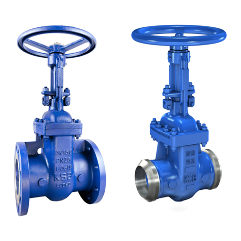
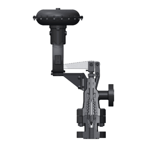
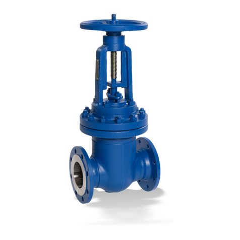
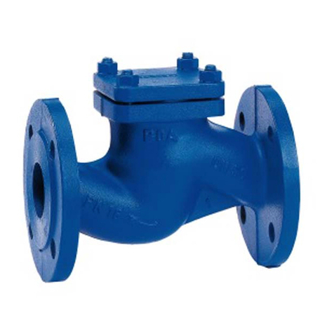
KSB ECOLINE-VA16 User manual

Globe Valve
ECOLINE-VA16
Operating Manual

Legal information
Operating Manual ECOLINE-VA16
All rights reserved. The contents provided herein ust neither be distributed, copied, reproduced,
edited or processed for any other purpose, nor otherwise trans itted, published or ade available to a
third party without the anufacturer's express written consent.
Subject to technical odification without prior notice.
KSB Italia SpA, Concorezzo 04/11/2018

ECOLINE
-
VA16
3
of
27
Contents
Glossary..........................................................................................................................................................................4
1 General ................................................................................................................................................... 5
1.1 Principles..................................................................................................................................... 5
1.2 Target group ................................................................................................................................. 5
1.3 Other applicable documents........................................................................................................... 5
1.4 Symbols ........................................................................................................................................ 5
2 Safety...................................................................................................................................................... 6
2.1 Key to safety symbols/markings ..................................................................................................... 6
2.2 General............................................................................................................................. 6
2.3 Intended use ........................................................................................................................... 7
2.4 Personnel qualification and training .............................................................................................. 7
2.5 Consequences and risks caused by non-compliance with this manual .................................................. 7
2.6 Safety awareness.................................................................................................................... 7
2.7 Safety information for the operator/user .................................................................................... 8
2.8 Safety information for maintenance, inspection and installation ...................................................... 8
2.9 Unauthorised modes of operation.................................................................................................. 8
3 General safety regulations ................................................................................................................... 9
4 Transport/Temporary Storage/Disposal ............................................................................................ 11
4.1 Checking the condition upon delivery .......................................................................................... 11
4.2 Transport.................................................................................................................... 11
4.3 Storage/preservation .................................................................................................................. 12
4.4 Return to supplier.................................................................................................................. 12
4.5 Disposal ........................................................................................................................................... 13
5 Valve Description ...................................................................................................................................... 14
5.1 General description ................................................................................................................... 14
5.2 Marking ............................................................................................................. 14
5.3 Operating data ............................................................................................................................ 16
5.4 Fluids handled ...................................................................................................................... 16
5.5 Design details ............................................................................................................................ 16
5.6 Pressure/temperature ratings................................................................................................. 16
5.7 Materials .............................................................................................................................. 17
5.8 Function .................................................................................................................... 18
5.9 Scope of supply.......................................................................................................................... 18
5.10 Dimensions and weights ........................................................................................................... 18
6 Installation at Site................................................................................................................................ 19
6.1 General information/Safety regulations ....................................................................................... 19
6.2 Installation ..................................................................................................................... 19
6.3 Insulation ……………………………………………………………………………………………………… 20
7 Commissioning/Start-up/Shutdown.............................................................................................................. 21
7.1 Commissioning/Start-up.............................................................................................................. 21
7.1.1 Prerequisites for commissioning/start-up.................................................................................. 21
7.1.2 Actuation ........................................................................................................ 21
7.2 Shutdown............................................................................................................................... 22
7.2.1 Measures to be taken for shutdown .................................................................................. 22
8 Servicing/Maintenance ....................................................................................................................... 23
8.1 Safety regulations ................................................................................................................. 23
8.2 Maintenance ............................................................................................................... 23
8.2.1 (Re-)tightening the bonnet bolting………………………………………………………………….. 24
8.2.2 (Re-)tightening the gland packing………………………………………………………………….. 24
9 Trouble-shooting................................................................................................................................. 25
Index ...............................................................................................................................................................26
Contents
Contents

4
of 2
7
ECOLINE
-
VA16
Glossary
Technical literature
Refer to the product catalogue for the technical
literature on our products at www.ksb.it
Contents

ECOLINE
-
VA16
5
of 2
7
1 General
1.1 Principles
This operating anual is supplied as an integral part of the type series and variants
indicated on the front cover. The anual describes the proper and safe use of this
equip ent in all phases of operation.
In the event of da age, i ediately contact the KSB sales organisation responsible
in order to aintain the right to clai under warranty.
1.2 Target group
This operating anual is ai ed at the target group of trained and qualified specialist
technical personnel.
1.3 Other applicable documents
Table 1: Overview of other applicable documents
Document Contents
Type series booklet Description of the valve
General asse bly drawing
2)
Sectional drawing of the valve
Sub
-
supplier product lit
erature
3)
Operating anuals and other product literature
for the accessories
Observe the relevant anufacturer's product literature for the accessories.
1.4 Symbols
Table 2: Symbols used in this manual
Symbol Description
Conditions which need to be fu
lfilled before proceeding with the
step-by-step instructions
⊳
Safety instructions
⇨
Result of an action
⇨
Cross-references
1.
2.
Step
-
by
-
step instructions
Note
Reco endations and i portant infor ation on how to handle
the product
1) If any
2) If inclusion in the scope of supply has been agreed; otherwise refer to the type series booklet.
3) If inclusion in the scope of supply has been agreed.
1 General

6
of 2
7
ECOLINE
-
VA16
2 Safety
All the information contained in this section refers to hazardous situations.
2.1 Key to safety symbols/markings
Table 3: Definition of safety symbols/markings
!
DAN G E R
DANGER
This signal word indicates a high-risk hazard which, if not avoided,
will result in death or serious injury.
!
WARNING
WARNING
This signal word indicates a ediu -risk hazard which, if not
avoided, could result in death or serious injury.
CAUTION
CAUTION
This signal word indicates a hazard which, if not avoided, could
result in da age to the achine and its functions.
General hazard
In conjunction with one of the signal words this sy bol indicates a
hazard which will or could result in death or serious injury.
Electrical hazard
In conjunction with one of the signal words this sy bol indicates a
hazard involving electrical voltage
and identifies infor ation about
protection against electrical voltage.
Machine damage
In conjunction with the signal word CAUTION this sy bol indicates a
hazard for the achine and its functions.
2.2 General
This anual contains general installation, operating and aintenance instructions
that ust be observed to ensure safe valve operation and prevent personal injury
and da age to property.
The safety infor ation in all sections of this anual ust be co plied with.
The operating anual ust be read and fully understood by the specialist personnel/
operators responsible prior to installation and co issioning.
The contents of this operating anual ust be available to the specialist personnel
at the site at all ti es.
Instructions and infor ation attached directly to the valve ust always be co plied
with and kept in a perfectly legible condition at all ti es. This applies to, for
exa ple: flow direction arrow, anufacturer, type designation, no inal pressure,
no inal size, year of construction and aterial.
The operator is responsible for ensuring co pliance with all local regulations not
taken into account in this operating anual.
The design, anufacture and testing of the valves are subject to a QM syste to
DIN EN ISO 9001. Co pliance with these require ents, however, is based on nor al,
predo inantly static loading.
Valves exposed to creep-rupture conditions have a li ited service life and have to
eet the applicable regulations stipulated in the technical codes.
In the case of custo ised special variants, further restrictions ay apply with regard
to the operating ode and service life. Please refer to the relevant sales literature for
this infor ation.
This operating anual does not take into account:
Any eventualities or incidents which ay occur during installation perfor ed by
the custo er, operation and aintenance.
Local regulations; the operator ust ensure that such regulations are strictly
observed by all, including the personnel called in for installation.
2 Safety
DANGE
R

ECOLINE
-
VA16
7
of 2
7
2.3 Intended use
•Only operate valves which are in perfect technical condition.
•Do not operate partially asse bled valves.
•The valve ust only be used for fluids specified in the product literature.
•Only operate the valve within the per issible operating range specified for
pressure and te perature.
•The valve's design and rating are based on predo inantly static loading in
accordance with the codes applied. Consult the anufacturer if the valve is
subjected to dyna ic loads or any other additional influences.
•Consult the anufacturer about any other odes of operation not described in
the product literature.
Prevention of foreseeable misuse
•Never exceed the per issible operating li its specified in the data sheet or
product literature regarding pressure, te perature, etc.
•Observe all safety infor ation and instructions in this operating anual.
2.4 Personnel qualification and training
All personnel involved ust be fully qualified to transport, install, operate, aintain
and inspect the product this anual refers to and be fully aware of the interaction
between the valve and the syste .
The responsibilities, co petence and supervision of all personnel involved in
transport, installation, operation, aintenance and inspection ust be clearly
defined by the operator.
Deficits in knowledge ust be rectified by eans of training and instruction
provided by sufficiently trained specialist personnel. If required, the operator can
co ission the anufacturer/supplier to train the personnel.
Hands-on training at the valve ust always be supervised by specialist technical
personnel.
2.5 Consequences and risks caused by non-compliance with this manual
•Non-co pliance with this operating anual will lead to forfeiture of warranty
cover and of any and all rights to clai s for da ages.
•Non-co pliance can, for exa ple, have the following consequences:
– Hazards to persons due to electrical, ther al, echanical and che ical
effects and explosions
– Failure of i portant product functions
– Failure of prescribed aintenance and servicing practices
– Hazard to the environ ent due to leakage of hazardous substances
2.6 Safety awareness
In addition to the safety infor ation contained in this anual and the intended use,
the following safety regulations shall be co plied with:
•Accident prevention, health and safety regulations
•Explosion protection regulations
•Safety regulations for handling hazardous substances
•Applicable standards, directives and laws
2 Safety

8
of 2
7
ECOLINE
-
VA16
2.7 Safety information for the operator/user
Actuator-operated valves are intended for use in areas which cannot be accessed by
unauthorised persons. Operation of these valves in areas which can be accessed by
unauthorised persons is only per itted if appropriate protective devices are fitted at
the site. This ust be ensured by the operator.
•The operator shall fit contact guards for hot, cold and oving parts and check
that the guards function properly.
•Do not re ove any contact guards during operation.
•Provide the personnel with protective equip ent and ake sure it is used.
•Contain leakages (e.g. at the ste seal) of hazardous fluids (e.g. explosive, toxic,
hot) so as to avoid any danger to persons and the environ ent. Adhere to all
relevant laws.
•Eli inate all electrical hazards. (In this respect refer to the applicable national
safety regulations and/or regulations issued by the local energy supply
co pan ies.)
2.8 Safety information for maintenance, inspection and installation
•Modifications or alterations of the valve require the anufacturer's prior
consent.
•Use only original spare parts or parts authorised by the anufacturer. The use of
other parts can invalidate any liability of the anufacturer for resulting da age.
•The operator ensures that aintenance, inspection and installation is perfor ed
by authorised, qualified specialist personnel who are thoroughly fa iliar with
the anual.
•Carry out work on the valve during standstill only.
•The valve body ust have cooled down to a bient te perature.
•The pressure in the valve body ust have been released and the valve ust have
been drained.
•When taking the valve out of service always adhere to the procedure described
in the anual.
(
ð
Section 7.2.1, Page 22)
•Deconta inate valves which handle fluids posing a health hazard.
•As soon as the work has been co pleted, re-install and re-activate any safety-
relevant and protective devices. Before returning the product to service, observe
all instructions on co issioning.
2.9 Unauthorised modes of operation
Never operate the valve outside the li its stated in the data sheet and in this
operating anual.
The warranty relating to the operating reliability and safety of the valve supplied is
only valid if the valve is used in accordance with its intended use.
(
ð
Section 2.3, Page 7)
2 Safety

ECOLINE
-
VA16
9
of
27
3 General safety regulations
DANGER
Handling actuated valves
Danger to life!
▷
If the valves are fitted with actuators, ensure that the actuator's operating
anual is also observed.
DANGER
Surge pressure/water hammer potentially occurring at high temperatures
Danger to life caused by burns or scalds!
▷
The ax. per issible valve pressure ust not be exceeded
(
ð
Section 5, Page 16).
▷
Use valves ade of nodular cast iron or steel.
▷
Operator shall provide general safety easures for the syste .
WARNING
Fluids handled, consumables and supplies which are hot and/or pose a health
hazard
Hazard to persons and the environ ent!
▷
Collect and properly dispose of flushing fluid and any fluid residues.
▷
Wear safety clothing and a protective ask if required.
▷
Observe all legal regulations on the disposal of fluids posing a health hazard.
WARNING
Cold/hot piping and/or valve
Risk of ther al injury!
▷
Insulate the valve.
▷
Attach warning signs.
WARNING
Impermissible piping forces
Leakage fro or rupture of the valve body!
▷
Connect the pipes to the valve without trans itting any stresses or strains.
▷
Take constructional easures to prevent any piping forces fro being
trans itted to the valve.
WARNING
Unqualified personnel performing work on the valve
Risk of injury!
▷
Always have repair and aintenance work perfor ed by specially trained,
qualified personnel.

10
of 2
7
ECOLINE
-
VA16
3 General safety regulations
CAUTION
Condensation water forming in air-conditioning, cooling and refrigerating systems
Ice for ing!
Blockage of actuating ele ent!
Da age due to corrosion!
▷
Insulate the valve to prevent diffusion.
CAUTION
Improper installation
Da age to the valve!
▷
Re ove the caps prior to installation.
▷
Clean the ating flange faces.
▷
Protect the body and bonnet/cover fro any i pacts.
CAUTION
Outdoor installation
Da age due to corrosion!
▷
Protect the valve appropriately against oisture.
CAUTION
Painting of pipes
I pair ent of the valve's function and loss of infor ation!
▷
Protect ste and plastic co ponents prior to applying paint.
▷
Protect printed na e plates prior to applying paint.
CAUTION
Impermissible load
Da age to the actuating ele ent!
▷
Do not use the valve as a foothold.
CAUTION
Improper reassembly
Da age to the valve!
▷
Reasse ble the valve in accordance with the general rules of sound
engineering practice.
▷
Use original spare parts only.

ECOLINE
-
VA16
11
of 2
7
4 Transport/Temporary Storage/Disposal
4.1 Checking the condition upon delivery
1. On transfer of goods, check each packaging unit for da age.
2. In the event of in-transit da age, assess the exact da age, docu ent it and
notify
KSB
or the supplying dealer and the insurer about the da age in writing
i ediately.
4.2 Transport
Always close the valve anually before transporting it. The valve is delivered ready
for operation and its line connection ports ay still be closed with caps, if
applicable. Original spare parts are only ready for operation following
asse bly/installation and subsequent shell and leak testing of the valve.
DANGER
The valve could slip out of the suspension arrangement
Danger to life fro falling parts!
▷
Only transport the valve in the specified position
▷
Never suspend the valve fro its handwheel
▷
Pay attention to the weight data and the centre of gravity
▷ Observe the applicable local accident prevention regulation
▷ Use suitable, per itted lifting accessories.
▷ Transport devices ( if any) on the actuator ay not be suitable for being
attached to a suspension arrange ent in order to transport the
valve/actuator asse bly. Refer to the actuator operating anual for the
per issible loads
To transport the valve, suspend it fro lifting tackle as illustrated.

12
of 2
7
ECOLINE
-
VA16
4 Transport/Temporary Storage/Disposal
4.3 Storage/preservation
If properly stored indoors, the equip ent is protected for a axi u of 12 onths.
This allows co issioning to take place so e ti e after delivery. We reco end
that the following easures be taken:
Store the valve in a dust-f ree and vibration-f ree, frost-proof roo where the
at ospheric hu idity is as constant as possible (use suitable caps or fil for
protection).
Close the valve using little force and store in the closed position.
Protect the valve fro contact with solvents, lubricants, fuels or other che icals.
4.4 Return to supplier
1. Drain the valve as described in the anual.
2. Always flush and clean the valve, particularly if it has been used for handling
noxious, explosive, hot or other hazardous fluids.
3. If the fluids handled by the syste leave residues which ight lead to corrosion
da age when co ing into contact with at ospheric hu idity, or which ight
ignite when co ing into contact with oxygen, the valve ust also be
neutralised and blown through with anhydrous inert gas for drying purposes.

ECOLINE
-
VA16
13
of 2
7
4 Transport/Temporary Storage/Disposal
4.5 Disposal
WARNING
Fluids handled, consumables and supplies which are hot and/or pose a health
hazard
Hazard to persons and the environ ent!
▷
Collect and properly dispose of flushing fluid and any fluid residues.
▷
Wear safety clothing and a protective ask if required.
▷
Observe all legal regulations on the disposal of fluids posing a health hazard.
1. Dis antle the valve.
Collect greases and other lubricants during dis antling.
2. Separate and sort the valve aterials, e.g. by:
- Metals
- Plastics
- Electronic waste
- Greases and other lubricants
3. Dispose of aterials in accordance with current regulations or in another
controlled anner.

14
of 2
7
ECOLINE
-
VA16
5 Valve Description
5.1 General description
The sectional drawings below provide exa ples of the general design/configuration
of the valve. For additional and ore detailed infor ation, refer to the respective
type series booklet.
5.2 Marking
Table 4: General marking
No inal size DN ...
No inal pressure class PN …
Manufacturer KSB
Type series/ odel ECOLINE-VA16
Year of consctruction 20..
Material JL 1040
Flow direction arrow ->
Traceability of the aterial ……
CE arking
Identification nu ber of the notified body 0036
5 Valve Description

ECOLINE
-
VA16
15
of 2
7
In accordance with the current Pressure Equipment Directive the valves are marked as
shown in the following table
Fluids group 2
5
.
3
O
p
According to the current Pressure Equipment Directive, Group 1 fluid comprises all
fluids posing physical or health hazards, e.g. fluid defined as
•Explosive
•Extremely flammable
•Highly flammable
•Flammable: the maximum allowable temperature is above flashpoint
•Very toxic
•Toxic
•Oxidising
Group 2 comprises all other fluids not referred to in Group 1
5 Valve Description

16
of 2
7
ECOLINE
-
VA16
5.3 Operating data
Table 5: Operating properties
Characteristic ECOLINE-VA16 Value
No inal pressure PN 16
No inal size DN 15-250
No inal size
Max. per issible pressure [bar]
16
Min . per issible te perature [°C]
-10
Max. per issible te perature [°C]
+300 *
5.4 Fluids handled
Water,
Water/glycol ixtures
Oil & Gas
Other fluids on request.
* ax te perature depending on working pressure, please check technical docu entation
5.5 Design details
Design
Valves to type series booklet ECOLINE-VA16
•Straight-way pattern with horizontal seat
•Rising handwheel
•Flanges to DIN EN 1092-2 type 21
•Exterior coating: blue, RAL 5002
•The valves satisfy the safety require ents of Annex I of the European Pressure
Equip ent Directive 2014/68/EU (PED) for fluids in Group 2
•The valves do not have a potential internal source of ignition and can be used in
potentially explosive at ospheres, Group II, category 2 (zones 1+21) and category 3
(zones 2+22) to Atex 2014/34/EU
Variants
•Position Indicator
•PTFE disc seat
5.6 Pressure/temperature ratings
Table 6:
Test pressure and operating pressure
PN
DN
Shell test Leak test (seat)
Permissible operating pressure [bar]
With water
Tests P10 and P11 to
DIN EN 12266-1
Test P12, leakage rate
A to DIN EN 12266-1
[°C]
[bar] [bar] -10 to 120 150 180
200
230
250
300
16 15 - 250 24 17.,6 16 14,4 13,4
12,8 11,8
11,2 9,6
5 Valve Description
5 Valve Description

ECOLINE
-
VA16
17
of 2
7
5.7 Materials
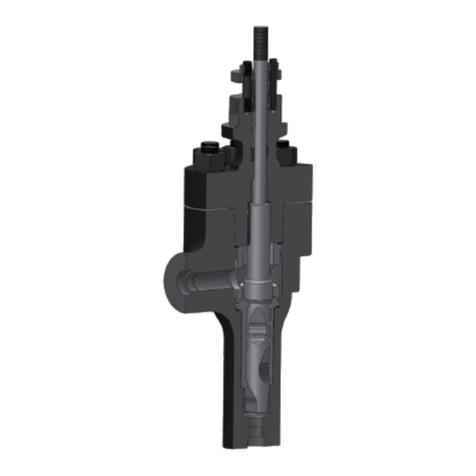
Fig. 2:
ECOLINE-VA16
Table 7:
Overview of available materials
Part No Description Material Note
1
Body EN-GJL-250
2
Bonnet EN-GJL-250
3
Shaft Stainlesss steeel 2 Cr13
4
Body seat Stainless steel 2 Cr13
5
Valve disc EN-GJL-250
6
Body/bonnet gasket Graphite
5 Valve Description

18
of 2
7
ECOLINE
-
VA16
5.8 Function
The valve consists of the pressure retaining parts, i.e. body (1) and bonnet (2).
The functional unit consists of valve disc (5), stem (3) and handwheel. Body (1) and bonnet (2) are joined by
means of hexagon head bolts, and hexagon nuts. The joint is sealed to atmosphere by joint ring (6) and
gland packing.
The functional unit basically consists of valve disc (5) and stem (3) and handwheel.
When delivered the gland packing is not fully tightened. The gland packing tightness should be performed on
site, applying a torque depending on the working conditions of the plant.
Periodically, depending on opening and closing cycles, the gland packing should be checked and in case it
should be tightened again.
The seat disc interface of body and disc is made of rust-proof materilas or PTFE rings (valve disc/PTFE
variant)
5.9 Scope of supply
Valve
Operating anual for each packaging unit
5.10 Dimensions and weights
For di ensions and weights please refer to the type series booklet.
5 Valve Description

ECOLINE
-
VA16
19
of 2
7
6 Installation at Site
6.1 General information/Safety regulations
Responsibility for positioning and installing the valve lies with the consultant,
construction co pany or operator/user. Planning and installation errors ay i pair
the reliable function of the valve and pose a substantial safety hazard.
6.2 Installation
CAUTION
Welding in close proximity to soft-seated valves
Da age to the seat/disc interface!
▷
Ensure that the valve is not heated beyond the te perature li its specified in
the type series booklet.
Responsibility for welding the valves into the piping and for any heat treat ent
required lies with the co issioned co pany or the plant operator.
Only use fasteners (e.g. to DIN EN 1515-4) and flange gaskets (e.g. to DIN EN 1514)
ade of aterials approved for the respective valve size. Always use all flange bolt
holes provided when connecting the valve to the pipe. Refer to the type series
booklet for details on flange connections.
NOTE
Exception: DN 65 PN 16
When using
steel flanges to DIN EN 1092-1 in conjunction with cast iron valves with
flanges achined to DIN EN 1092-2, ensure that for no inal size DN 65 classed PN
16 the ating flanges are fitted offset by 22.5°.
Table 8:
Valve bolting DN 65 PN 16
NOTE
For the valves to reach the docu ented Kv values, the flow direction ust
correspond to the flow direction arrow
NOTE
An alternating direction of flow is per itted unless restrictions apply to specific
produtcs.
6 Installation at Site

20
of 2
7
EC
OLINE
-
VA16
6 Installation at Site
To avoid warping of the valve during or following installation, open the valve by
approxi ately two handwheel turns in anti-clockwise direction
If the following differential pressures are exceeded fro DN 200 upwards, a
balanced plug design is required.
DN 200 250 300/350
PN 16 Δp bar 12 9 6
6.3 Insulation
For handling hot fluids, the valve should be insulated in accordance with the Ger an
energy-saving regulations
CAUTION
Condensation water for ing in air-conditioning, cooling and refrigerating syste
Ice for ing!
Blockage of actuating ele ent!
Da age due to corrosion!
▷ Insulate the valve to prevent diffusion
CAUTION
Installation of the valve with the stem pointing downwards
Dirt collecting between the folds and the gland packing!
Valve blockage!
▷
Install the valve with the ste pointing upwards or to the side.
WARNING
Installation of the valve with the stem pointing downwards in steam application
Da age of the valve through stea ha er!
▷
Install the valve with the ste pointing upwards or to the side.
Table of contents
Other KSB Control Unit manuals

KSB
KSB ISORIA 10 User manual

KSB
KSB ECOLINE GT 40 User manual

KSB
KSB MIL 41000 User manual

KSB
KSB ISORIA 10 Installation instructions

KSB
KSB STAAL 40 AKD User manual

KSB
KSB BOA-Control IMS User manual

KSB
KSB BOA-CVE C User manual

KSB
KSB APORIS Series User manual

KSB
KSB MIL 21000 User manual

KSB
KSB UPA User manual

KSB
KSB ECOLINE GLF User manual

KSB
KSB TRIODIS 150 User manual

KSB
KSB AMTRONIC R1300 User manual

KSB
KSB ECOLINE VA 40 User manual

KSB
KSB MIL 77000 User manual

KSB
KSB Cervomatic EDP.2 User manual

KSB
KSB ECOLINE GTF Series User manual

KSB
KSB MIL 10000 User manual

KSB
KSB BOA-H Mat P Installation instructions

KSB
KSB MSE User manual