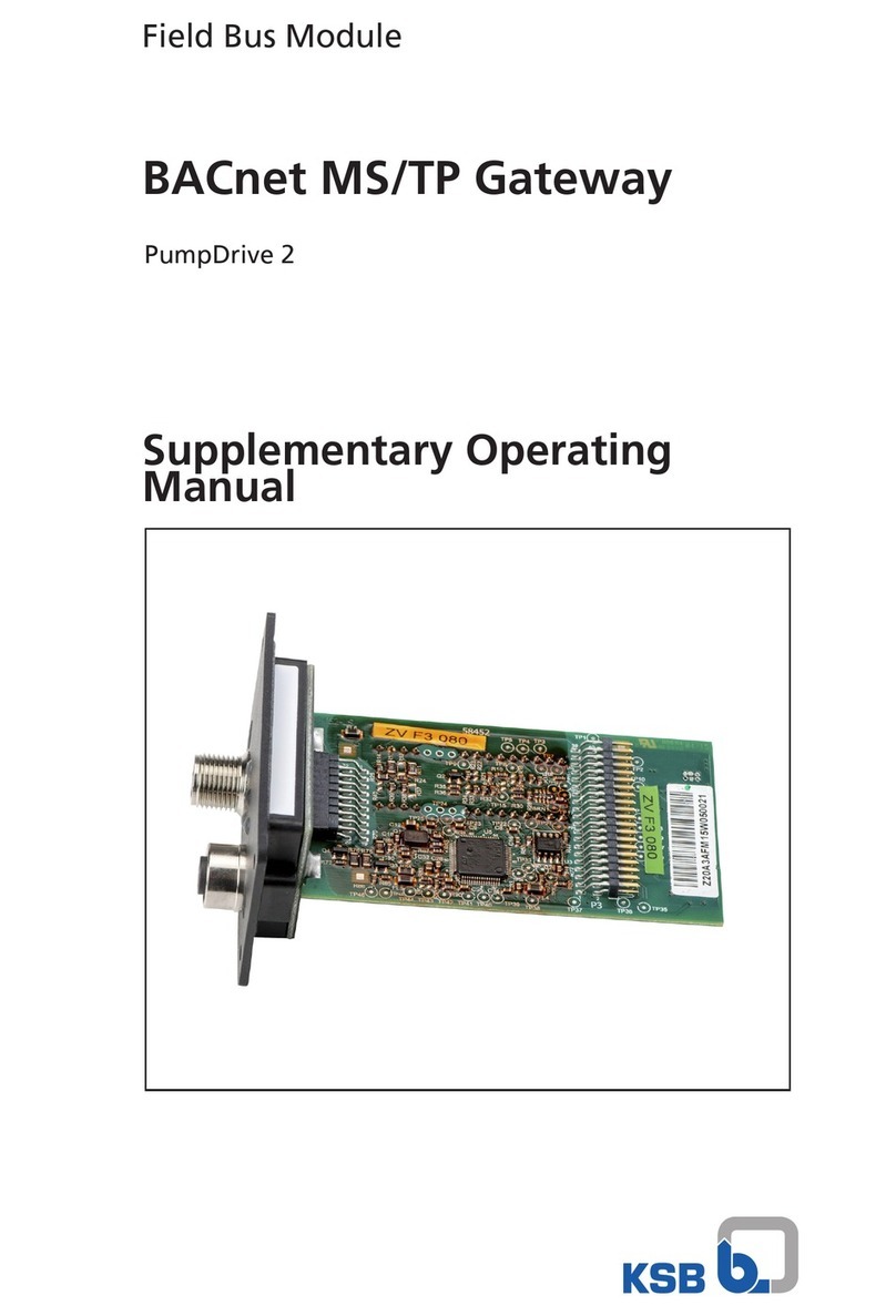
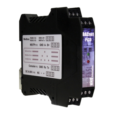
KSB AmaControl INT 600 DM User manual

Protection Module for Water and Waste
Water Products
AmaControl
INT 600 DM Gateway
Supplementary Operating
Manual

Legal information/Copyright
Supplementary Operating Manual AmaControl
Original operating manual
All rights reserved. The contents provided herein must neither be distributed, copied, reproduced,
edited or processed for any other purpose, nor otherwise transmitted, published or made available to a
third party without the manufacturer's express written consent.
Subject to technical modification without prior notice.
© KSB SE & Co. KGaA, Frankenthal 2023-04-13

Contents
3 of 48
AmaControl
Contents
1 Supplementary Operating Manual....................................................................................................... 4
1.1 General..............................................................................................................................................................4
1.2 INT 600 DM Gateway........................................................................................................................................4
1.2.1 Functional description of the INT 600 DM Gateway......................................................................... 4
1.2.2 Application of INT 600 DM Gateway ................................................................................................. 5
1.3 Configuration of INT 600 DM Gateway ..........................................................................................................6
1.3.1 Safety regulations ............................................................................................................................... 6
1.3.2 Setting Modbus start addresses for INT 600 DM Gateway............................................................... 6
1.3.3 Setting the baud rate ......................................................................................................................... 7
1.3.4 Setting stop bits and parity ................................................................................................................ 8
1.3.5 Monitoring the DP ports .................................................................................................................... 8
1.3.6 Modbus termination........................................................................................................................... 9
1.3.7 Modbus start register ......................................................................................................................... 9
1.3.8 Triggering remote reset ................................................................................................................... 10
1.4 Modbus Protocol ............................................................................................................................................10
1.4.1 Modbus protocol, AmaControl 3 ..................................................................................................... 10
1.4.2 Modbus protocol, AmaControl 4 (Modbus interface) .................................................................... 20
1.4.3 Modbus protocol, AmaControl 4 (DP interface INT 600 DM Gateway) ......................................... 30
1.4.4 Modbus protocol, AmaControl L...................................................................................................... 35
1.4.5 Overview of the most important registers ...................................................................................... 40
1.4.6 Modbus error list............................................................................................................................... 42
1.5 Related Documents ........................................................................................................................................44
1.5.1 Technical data of INT 600 DM Gateway .......................................................................................... 44
1.5.1.1 Wiring diagram of INT 600 DM Gateway ................................................................................46
1.5.1.2 Outline drawing of INT 600 DM Gateway...............................................................................46

1 Supplementary Operating Manual
4 of 48 AmaControl
2301.83/04-EN
1 Supplementary Operating Manual
1.1 General
This supplementary operating manual accompanies the installation/operating
manual. All information contained in the installation/operating manual must be
observed.
Table1: Relevant operating manuals
Type series Reference number of the installation/operating
manual
Amacontrol 2301.82
1.2 INT 600 DM Gateway
1.2.1 Functional description of the INT 600 DM Gateway
AmaControl devices can be read in and converted to the Modbus protocol via the
five DP inputs. Built-in LEDs indicate the current activities of the gateway.
The INT 600 DM Gateway has the following features:
▪Direct plug-type connection of AmaControl
▪Simple analysis of the interfaces during data transmission by means of function
LEDs
▪Straightforward mounting for control cabinet installation
▪Wide range of applications due to dual-voltage power supply unit
▪Extended temperature range for use in outdoor control cabinets
▪Remote reset possible
▪Air gap: no possibility of accessing the protection devices from the Internet
▪Connection to customer's control system (Modbus RTU protocol)
▪Shock and vibration resistant
▪cURus approval
Modbus
The Modbus interface supports the standard Modbus function code.
Table2: Standard Modbus function code
Standard Modbus function code Description
0x04 Read input register
0x03 Read holding register
0x10 Preset multiple registers
Overview of flashing code
Table3: Modbus flashing codes
Modbus Description
Steady green Device switched ON
Flashing green Initialisation phase
Flashing yellow Valid data telegrams are being received
for the set address
Flashing red Error during data transmission
Table4: DP flashing codes
DP Description
Flashing yellow Valid data telegrams are being received
from AmaControl

1 Supplementary Operating Manual
5 of 48
AmaControl
2301.83/04-EN
1.2.2 Application of INT 600 DM Gateway
DANGER
Incorrect electrical installation
Risk of fatal injury due to electric shock!
▷Always have the electrical connections installed by specialist personnel.
▷Observe the technical specifications of the local and national energy supply
companies.
DANGER
Electric shock
▷Connected sensors and connection cables outed out of the control cabinet must
have at least basic insulation.
NOTE
Short circuit
▷Only KSB AmaControl devices may be connected to the DP interface.
The diagnostic system can output data recorded by AmaControl via the DP interface.
The operating status of the pump can thus be evaluated in the actual application.
Incidents can be responded to immediately.
The INT 600 DM Gateway reads in the DP interface. It then outputs the data via an
RS485 interface (Modbus RTU protocol).
Type series Modbus interface DP interface via INT 600
DM Gateway
AmaControl 3 - ✘
AmaControl L - ✘
AmaControl 4 ✘ ✘

1 Supplementary Operating Manual
6 of 48 AmaControl
2301.83/04-EN
1.3 Configuration of INT 600 DM Gateway
1.3.1 Safety regulations
DANGER
Contact with live components
Danger of death from electric shock!
▷Any settings on the device shall only be performed when it has been
disconnected from the power supply (de-energised).
1.3.2 Setting Modbus start addresses for INT 600 DM Gateway
Fig.1: The settings can be configured using DIP switches 1 and 2.
Table5: Configuring DIP switches
DIP switch 1 DIP switch 2 Address
OFF OFF #1
ON OFF #17
OFF ON #33
ON ON #49
Table6: Configuring DIP switches
Address DP Device
#1 1 First
#2 1 Second
#3 1 Third
#4 2 First
#5 2 Second
#6 2 Third

1 Supplementary Operating Manual
7 of 48
AmaControl
2301.83/04-EN
Example Each INT 600 DM Gateway DP input uses 3 Modbus addresses. The first device on DP1
#1, the second device on DP2 #4 etc. The INT 600 DM Gateway itself uses address #16
(start address +15). The 3 addresses are provided for additional AmaControl devices
at a DP input. For AmaControl only the 1st address is available, resulting in the
following Modbus address assignment for the AmaControl devices:
Table7: Modbus address assignment
Start address
DP1
AmaControl1
DP2
AmaControl2
DP3
AmaControl3
DP4
AmaControl4
DP5
AmaControl5
INT 600 DM
Gateway
1 1 4 7 10 13 16
17 17 20 23 26 29 32
33 33 36 39 42 45 48
49 49 52 55 58 61 64
NOTE
Due to the defined Modbus addresses, a maximum of 20 AmaControl devices can be
connected in one network.
1.3.3 Setting the baud rate
Baud rate
Fig.2: Setting the baud rate via DIP switches 3 and 4
Table8: Selection of the baud rate
DIP switch 3 DIP switch 4 Address
OFF OFF 9600
ON OFF 19200 (factory setting)
OFF ON 38400
ON ON 57600

1 Supplementary Operating Manual
8 of 48 AmaControl
2301.83/04-EN
1.3.4 Setting stop bits and parity
Stop bits / parity
Fig.3: Setting stop bits and parity via DIP switches 5 and 6
Table9: Selection of stop bits / parity
DIP switch 5 DIP switch 6 Address
OFF OFF 1 / even
ON OFF 1 / odd
OFF ON 2 / no (factory setting)
ON ON 1 / no
1.3.5 Monitoring the DP ports
DP port monitoring After connecting and parameterising the Modbus communication, the settings can
be saved by means of DIP switch7. If a failure of the AmaControl devices connected
to the DP ports is registered, the error status (1= error) is displayed in the "dec9734
(FC4)" register of the INT 600 DM Gateway. Alerts are issued with a delay of about
2minutes. Parallel to this message the respective seconds counters of the individual
AmaControl devices can be read out (FC4) for an additional evaluation (e.g.used as a
sign of life) (ðSection1.4.5,Page40) .
Fig.4: Activating DP port monitoring via DIP switch 7
Table10: DP port monitoring
DIP switch 7 Address
ON Activated
OFF Deactivated

1 Supplementary Operating Manual
9 of 48
AmaControl
2301.83/04-EN
1.3.6 Modbus termination
Termination
Fig.5: Setting terminating resistor for Modbus RTU via DIP switch 8
Table11: Setting terminating resistor
DIP switch 8 Address
ON Activated
OFF Deactivated (factory setting)
1.3.7 Modbus start register
The Modbus start registers of the different AmaControl devices when accessing
Modbus INT 600 DM Gateway are as follows:
Table12: Modbus start register
Designation Device type Start register Direct
access
via Modbus
interface
Start register Access
via DP port of INT
600 DM Gateway
AmaControl L xxA712 ✘10752
AmaControl 3 xxA701 ✘8192
AmaControl 4 xxA721 8192 10752
AmaControl L, 3
AmaControl L and AmaControl 3 can only be read out via INT 600 DM Gateway with
function code FC4 (Read Input Register).
Further information on Modbus protocols
AmaControl 3: (ðSection1.4.4,Page35)
AmaControl L: (ðSection1.4.1,Page10) .
AmaControl 4
AmaControl 4 can only be read out via INT 600 DM Gateway with function code (FC4)
(Read Input Register). The register addresses in Table (ðSection1.4.3,Page30)
and (ðSection1.4.2,Page20) apply. Direct access via the separate Modbus
interface: The register addresses according to Modbus supplementary operating
manual (ðSection1.4.2,Page20) are valid. Parameter settings must be read with
(FC3). Operating values are read with (FC4).
The Modbus RTU masters used must support (FC3) and (FC4) for readout, if all
AmaControl device types are used. Parameters in the AmaControl cannot be written
via Modbus. Writing parameters in the INT 600 DM Gateway is possible with (FC10).

1 Supplementary Operating Manual
10 of 48 AmaControl
2301.83/04-EN
1.3.8 Triggering remote reset
INT 600 DM Gateway provides a volt-free changeover contact for resetting fault
messages. The relay is controlled via register dec 9735. Sequence of control
commands with (FC10) (Preset Multiple Registers): write dec 15,300 once and then
dec 42,455. The relay then switches on for 5seconds. A remote reset is possible a
maximum of 3times in 24hours and no more than oncein 30minutes. The reset
should take no longer than 5seconds. (ðSection1.5.1.1,Page46)
1.4 Modbus Protocol
1.4.1 Modbus protocol, AmaControl 3
NOTE
The AmaControl 3 Modbus registers are read using the INT 600 DM Gateway.
Table13: Modbus protocol, AmaControl 3
Start End Description Data type
8192 8192 High byte: visual ID
Low byte: reserved
u 16bit
8193 8193 High (12 bit): article main number
Low (4 bit): reserved
u 16bit
8194 8195 Consecutive serial number within the article number u 32bit
8196 8196 Ohmic value of motor temperature sensor
1-65535Ω, 0 = not available
u 16bit
8198 8198 Fault message
Bit 0: 0 = no fault, 1 = at least one fault currently present
u 16bit
8199 8199 Status message
Bit 0: motor status: 0 = motor at standstill, 1 = motor running
u 16bit
8202 8202 Motor temperature
Temperature = (value - 32768) / 100
-327.00 °C…+327.00 °C
s 16bit
8206 8206 Software revision
High byte: major software revision number
Low byte: minor software revision number
Displayed: major.minor (e.g. 1.02)
u 16bit
8207 8207 Data matrix functional variant
0 = engineering sample
1-9 = variants in ascending order
u 16bit
8210 8210 Article number variants
If value < 10000
"S" [value]
If value > 10000
"P" [value - 10000]
u 16bit
8211 8211 Voltage key
22 = Dual voltage 115-230 VAC
31 = 24 VAC
13 = 24 VDC
u 16bit
8212 8213 Total number of fault trips
0…327675
Little-endian
u 32bit
8214 8215 Total number of operational trips
0...327675
Little-endian
u 32bit
8216 8216 Number of seconds of the current hour (internal time)
0-3599 s
u 16bit

1 Supplementary Operating Manual
11 of 48
AmaControl
2301.83/04-EN
Start End Description Data type
8223 8223 Mean value of frequency (all 3 phases)
0 = not assigned
1 = frequency 0 Hz
2 = incorrect phase sequence
3…65535 motor supply frequency in Hz
u 16bit
8228 8228 Number of hours of the current day (internal time)
0-23 h
u 8bit
8230 8230 Total number of starts of the current day (internal time)
0...255
u 8bit
8232 8232 Total number of starts of the previous day (current day - 1 day; internal
time)
0…255
u 8bit
8233 8233 Total number of starts two days ago (current day - 2 days; internal time)
0...255
u 8bit
8234 8234 Total number of starts three days ago (current day - 3 days; internal time)
0...255
u 8bit
8235 8235 Total number of starts four days ago (current day - 4 days; internal time)
0...255
u 8bit
8236 8236 Total number of starts five days ago (current day - 5 days; internal time)
0...255
u 8bit
8237 8237 Total number of starts six days ago (current day - 6 days; internal time)
0...255
u 8bit
8240 8240 Switching cycles of the current hour (internal time)
0...255
u 8bit
8241 8241 Maximum of the switching cycles per hour of the current day (internal
time)
0...255
u 8bit
8242 8242 Maximum of the switching cycles per hour of the previous day (current
day - 1 day; internal time)
0...255
u 8bit
8243 8243 Maximum of the switching cycles per hour of two days ago (current day -
2 days; internal time)
0...255
u 8bit
8244 8244 Maximum of the switching cycles per hour of three days ago (current
day- 3 days; internal time)
0...255
u 8bit
8245 8245 Maximum of the switching cycles per hour of four days ago (current day -
4 days; internal time)
0...255
u 8bit
8246 8246 Maximum of the switching cycles per hour of five days ago (current day -
5 days; internal time)
0...255
u 8bit
8247 8247 Maximum of the switching cycles per hour of six days ago (current day - 6
days; internal time)
0...255
u 8bit
8248 8248 Module condition, motor temperature monitoring
High byte: error number
Low byte: module condition, bit-coded
Bit 0 = active
Bit 1 = warning
Bit 2 = fault
Bit 3 = re-start delay
Bit 4 = interlocked
u 16bit

1 Supplementary Operating Manual
12 of 48 AmaControl
2301.83/04-EN
Start End Description Data type
8251 8251 Module condition, relay monitoring
High byte: error number
Low byte: module condition, bit-coded
Bit 0 = active
Bit 1 = warning
Bit 2 = fault
Bit 3 = re-start delay
Bit 4 = interlocked
u 16bit
8252 8252 Module condition, frequency of starts monitoring
High byte: error number
Low byte: module condition, bit-coded
Bit 0 = active
Bit 1 = warning
Bit 2 = fault
Bit 3 = re-start delay
Bit 4 = interlocked
u 16bit
8260 8260 Module condition, general monitoring
High byte: error number
Low byte: module condition, bit-coded
Bit 0 = active
Bit 1 = warning
Bit 2 = fault
Bit 3 = re-start delay
Bit 4 = interlocked
u 16bit
8262 8262 Module condition, supply voltage monitoring
High byte: error number
Low byte: module condition, bit-coded
Bit 0 = active
Bit 1 = warning
Bit 2 = fault
Bit 3 = re-start delay
Bit 4 = interlocked
u 16bit
8266 8266 Module condition, temperature input 1
High byte: error number
Low byte: module condition, bit-coded
Bit 0 = active
Bit 1 = warning
Bit 2 = fault
Bit 3 = re-start delay
Bit 4 = interlocked
u 16bit
8267 8267 Module condition, temperature input 2
High byte: error number
Low byte: module condition, bit-coded
Bit 0 = active
Bit 1 = warning
Bit 2 = fault
Bit 3 = re-start delay
Bit 4 = interlocked
u 16bit
8276 8276 Current running time of the motor
0..65 535 min
u 16bit
8277 8277 Number of running times <1 min
Number to determine the quasi-percentage distribution
u 8bit
8278 8278 Number of running times <5 min
Number to determine the quasi-percentage distribution
u 8bit
8279 8279 Number of running times 5 - 9 min
Number to determine the quasi-percentage distribution
u 8bit
8280 8280 Number of running times 10 - 19 min
Number to determine the quasi-percentage distribution
u 8bit
8281 8281 Number of running times 20 - 29 min
Number to determine the quasi-percentage distribution
u 8bit

1 Supplementary Operating Manual
13 of 48
AmaControl
2301.83/04-EN
Start End Description Data type
8282 8282 Number of running times 30 - 59 min
Number to determine the quasi-percentage distribution
u 8bit
8283 8283 Number of running times 60 - 119 min
Number to determine the quasi-percentage distribution
u 8bit
8284 8284 Number of running times 120 - 300 min
Number to determine the quasi-percentage distribution
u 8bit
8285 8285 Number of running times >300 min
Number to determine the quasi-percentage distribution
u 8bit
8302 8302 Sum over lifetime: motor sensor open circuit
Alert
The following error numbers are counted: {10},{41}
u 16bit
8303 8303 Sum over lifetime: motor sensor short circuit
Alert
The following error numbers are counted: {8},{40}
u 16bit
8306 8306 Sum over lifetime: motor temperature static tripping
Alert
The following error numbers are counted: {2},{15},{38},{39},{55}
u 16bit
8307 8307 Sum over lifetime: motor temperature static tripping
Alert, interlocked
u 16bit
8316 8316 Sum over lifetime: phase loss
Alert
The following error numbers are counted: {28}
u 16bit
8317 8317 Sum over lifetime: phase loss
Alert, interlocked
u 16bit
8318 8318 Sum over lifetime: limit of frequency of starts
Alert
The following error numbers are counted: {7}
u 16bit
8319 8319 Sum over lifetime: motor detected as running even though the relay was
switched OFF
Message
The following error numbers are counted: {11},{118}
u 16bit
8320 8320 Sum over lifetime: power reset
Message
The following event numbers are counted: {1}
u 16bit
8321 8321 Sum over lifetime: successful parameter change
Message
u 16bit
8331 8331 Sum over lifetime: phase sequence error
Alert, interlocked
The following event numbers are counted: {27}
u 16bit
8334 8334 Remaining delay period
Estimated time before the motor can be switched on again
0..65533 sec
65,535 = interlocked tripping
65,534 = time undefined
u 16bit
8336 8336 Time since last fault in minutes/hours
0..120 = 0…120 min
121..238 = 3..120 h
u 8bit
8337 8337 Time since last fault in days
0 = 0 days
1…246 = 6…251 days
u 8bit
8338 8338 Sum of motor running time although the relay was switched off
Value * 10 min
u 16bit
8342 8342 Sum over lifetime: phase asymmetry detected
Warning
The following event numbers are counted: {110}
u 16bit

1 Supplementary Operating Manual
14 of 48 AmaControl
2301.83/04-EN
Start End Description Data type
8344 8344 Sum over lifetime: phase asymmetry detected
Alert
The following event numbers are counted: {29}
u 16bit
8345 8345 Sum over lifetime: phase asymmetry detected
Alert, interlocked
u 16bit
8348 8348 Sum over lifetime: internal fault
Warning
The following event numbers are counted: {100}, {101}, {102}, {103},
{104}, {105}, {106}, {107}, {109}
u 16bit
8349 8349 Sum over lifetime: internal fault
Alert
The following event numbers are counted: {31}
u 16bit
8350 8350 Sum over lifetime: supply voltage, undervoltage
Warning
The following event numbers are counted: {108},{113},{115}
u 16bit
8351 8351 Sum over lifetime: supply voltage, undervoltage
Alert
The following error numbers are counted: {37}
u 16bit
8352 8352 Fault history: error number of 1st (most recent) error u 8bit
8353 8353 Fault history: time between the first (most recent) error and the error
before that
0..120 = 0..120 min
121..238 = 3..120 h
u 8bit
8356 8356 Fault history: error number of 2nd (second most recent) error u 8bit
8357 8357 Fault history: time between the 2nd (second most recent) error and the
error before that
0..120 = 0..120 min
121..238 = 3..120 h
u 8bit
8360 8360 Fault history: error number of 3rd error u 8bit
8361 8361 Fault history: time between the 3rd error and the error before that
0..120 = 0..120 min
121..238 = 3..120h
u 8bit
8364 8364 Fault history: error number of the 4th error u 8bit
8365 8365 Fault history: time between the 4th error and the error before that
0..120 = 0..120 min
121..238 = 3..120h
u 8bit
8368 8368 Fault history: error number of the 5th error u 8bit
8369 8369 Fault history: time between the 5th error and the error before that
0..120 = 0..120 min
121..238 = 3..120 h
u 8bit
8372 8372 Fault history: error number of the 6th error u 8bit
8373 8373 Fault history: time between the 6th error and the error before that
0..120 = 0..120 min
121..238 = 3..120 h
u 8bit
8376 8376 Fault history: error number of the 7th error u 8bit
8377 8377 Fault history: time between the 7th error and the error before that
0..120 = 0..120 min
121..238 = 3..120 h
u 8bit
8380 8380 Fault history: error number of the 8th error u 8bit
8381 8381 Fault history: time between the 8th error and the error before that
0..120 = 0..120 min
121..238 = 3..120 h
u 8bit
8384 8384 Fault history: error number of the 9th error u 8bit
8385 8385 Fault history: time between the 9th error and the error before that
0..120 = 0..120 min
121..238 = 3..120 h
u 8bit

1 Supplementary Operating Manual
15 of 48
AmaControl
2301.83/04-EN
Start End Description Data type
8388 8388 Fault history: error number of the 10th error u 8bit
8389 8389 Fault history: time between the 10th error and the error before that
0..120 = 0..120 min
121..238 = 3..120 h
u 8bit
8392 8392 Fault history: error number of the 11th error
Error number
u 8bit
8393 8393 Fault history: time between the 11th error and the error before that
0..120 = 0..120 min
121..238 = 3..120 h
u 8bit
8396 8396 Fault history: error number of the 12th error
Error number
u 8bit
8397 8397 Fault history: time between the 12th error and the error before that
0..120 = 0..120 min
121..238 = 3..120 h
u 8bit
8400 8400 Fault history: error number of 13th error
Error number
u 8bit
8401 8401 Fault history: time between the 13th error and the error before that
0..120 = 0..120 min
121..238 = 3..120 h
u 8bit
8404 8404 Fault history: error number of the 14th error
Error number
u 8bit
8405 8405 Fault history: time between the 14th error and the error before that
0..120 = 0..120 min
121..238 = 3..120 h
u 8bit
8408 8408 Fault history: error number of the 15th error
Error number
u 8bit
8409 8409 Fault history: time between the 15th error and the error before that
0..120 = 0..120 min
121..238 = 3..120 h
u 8bit
8412 8412 Fault history: error number of the 16th error
Error number
u 8bit
8413 8413 Fault history: time between the 16th error and the error before that
0..120 = 0..120 min
121..238 = 3..120 h
u 8bit
8416 8416 Fault history: error number of the 17th error
Error number
u 8bit
8417 8417 Fault history: time between the 17th error and the error before that
0..120 = 0..120 min
121..238 = 3..120 h
u 8bit
8420 8420 Fault history: error number of the 18th error
Error number
u 8bit
8421 8421 Fault history: time between the 18th error and the error before that
0..120 = 0..120 min
121..238 = 3..120 h
u 8bit
8424 8424 Fault history: error number of the 19th error
Error number
u 8bit
8425 8425 Fault history: time between the 19th error and the error before that
0..120 = 0..120 min
121..238 = 3..120 h
u 8bit
8428 8428 Fault history: error number of the 20th error
Error number
u 8bit
8429 8429 Fault history: time between the 20th error and the error before that
0..120 = 0..120 min
121..238 = 3..120 h
u 8bit
8500 8500 Sum over lifetime: phase monitoring, undervoltage
Warning
The following event numbers are counted: {6},{116}
u 16bit

1 Supplementary Operating Manual
16 of 48 AmaControl
2301.83/04-EN
Start End Description Data type
8501 8501 Sum over lifetime: phase monitoring, overvoltage
Warning
u 16bit
8502 8502 Sum over lifetime: phase monitoring, undervoltage Alert u 16bit
8503 8503 Sum over lifetime: phase monitoring, undervoltage
Alert, interlocked
u 16bit
8504 8504 Sum over lifetime: phase monitoring, overvoltage
Alert
The following event numbers are counted: {46},{117}
u 16bit
8505 8505 Sum over lifetime: phase monitoring, overvoltage
Alert, interlocked
u 16bit
8508 8508 Motor temperature trip value
Temperature = (value - 32768) / 100
-327.00 °C…+327.00 °C
s 16bit
8554 8554 Module condition, leakage monitoring 1
High byte: error number
Low byte: module condition, bit-coded
Bit 0 = active
Bit 1 = warning
Bit 2 = fault
Bit 3 = re-start delay
Bit 4 = interlocked
u 16bit
8555 8555 Module condition, leakage monitoring 2
High byte: error number
Low byte: module condition, bit-coded
Bit 0 = active
Bit 1 = warning
Bit 2 = fault
Bit 3 = re-start delay
Bit 4 = interlocked
u 16bit
8556 8556 Module condition, phase sequence
High byte: error number
Low byte: module condition, bit-coded
Bit 0 = active
Bit 1 = warning
Bit 2 = fault
Bit 3 = re-start delay
Bit 4 = interlocked
u 16bit
8557 8557 Module condition, phase failure
High byte: error number
Low byte: module condition, bit-coded
Bit 0 = active
Bit 1 = warning
Bit 2 = fault
Bit 3 = re-start delay
Bit 4 = interlocked
u 16bit
8558 8558 Module condition, phase asymmetry
High byte: error number
Low byte: module condition, bit-coded
Bit 0 = active
Bit 1 = warning
Bit 2 = fault
Bit 3 = re-start delay
Bit 4 = interlocked
u 16bit

1 Supplementary Operating Manual
17 of 48
AmaControl
2301.83/04-EN
Start End Description Data type
8560 8560 Module condition, current loop
High byte: error number
Low byte: module condition, bit-coded
Bit 0 = active
Bit 1 = warning
Bit 2 = fault
Bit 3 = re-start delay
Bit 4 = interlocked
u 16bit
8562 8562 Sum over lifetime: temperature sensor 1
Warning
The following event numbers are counted: {123}
u 16bit
8563 8563 Sum over lifetime: temperature sensor 2, limit exceeded
Warning
The following event numbers are counted: {124}
u 16bit
8564 8564 Sum over lifetime: temperature sensor 1
Temperature exceeded
Alert
The following event numbers are counted: {56},{57}
u 16bit
8565 8565 Sum over lifetime: temperature sensor 1, temperature exceeded
Alert, interlocked
The following error numbers are counted: {56},{57}
u 16bit
8566 8566 Sum over lifetime: temperature sensor 1, short circuit
Alert
The following event numbers are counted: {58}
u 16bit
8567 8567 Sum over lifetime: temperature sensor 1, open circuit
Alert
The following event numbers are counted: {59}
u 16bit
8568 8568 Sum over lifetime: temperature sensor 2, temperature exceeded
Alert
The following event numbers are counted: {60},{61}
u 16bit
8569 8569 Sum over lifetime: temperature sensor 2, temperature exceeded
Alert, Interlocked
The following error numbers are counted: {60}, {61}
u 16bit
8570 8570 Sum over lifetime: temperature sensor 2, short circuit
Alert
The following event numbers are counted: {62}
u 16bit
8571 8571 Sum over lifetime: temperature sensor 2, open circuit
Alert
The following event numbers are counted: {63}
u 16bit
8572 8572 Sum over lifetime: leakage monitoring 1
Warning
The following event numbers are counted: {125}
u 16bit
8573 8573 Sum over lifetime: leakage monitoring 2
Warning
The following event numbers are counted: {126}
u 16bit
8574 8574 Sum over lifetime: leakage monitoring 1
Alert
The following error numbers are counted: {64},{65}
u 16bit
8575 8575 Sum over lifetime: leakage monitoring 1
Alert, interlocked
The following error numbers are counted: {64},{65}
u 16bit
8576 8576 Sum over lifetime: leakage monitoring 2
Alert
The following error numbers are counted: {66}, {67}
u 16bit
8577 8577 Sum over lifetime: leakage monitoring 2
Alert, interlocked
The following error numbers are counted: {66}, {67}
u 16bit

1 Supplementary Operating Manual
18 of 48 AmaControl
2301.83/04-EN
Start End Description Data type
8578 8578 Sum over lifetime: current loop, warning value exceeded
Warning
The following error numbers are counted: {127}
u 16bit
8579 8579 Sum over lifetime: current loop, sensor fault
Alert
The following error numbers are counted: {69}
u 16bit
8580 8580 Sum over lifetime: current loop, trip value exceeded
Alert
The following error numbers are counted: {68}
u 16bit
8581 8581 Sum over lifetime: current loop, trip value exceeded
Interlocked alert
The following error numbers are counted: {68}
u 16bit
8582 8582 Temperature sensor 1, temperature value
Temperature = (value - 32768) / 100
-327.00 °C…+327.00 °C
s 16bit
8583 8583 Temperature sensor 1, trip value
Temperature = (value - 32768) / 100
-327.00 °C…+327.00 °C
s 16bit
8584 8584 Temperature sensor 2, temperature value
Temperature = (value - 32768) / 100
-327.00 °C…+327.00 °C
s 16bit
8585 8585 Temperature sensor 2, trip value
Temperature = (value - 32768) / 100
-327.00 °C…+327.00 °C
s 16bit
8586 8586 Temperature sensor 1, ohmic value u 16bit
8587 8587 Temperature sensor 2, ohmic value u 16bit
8588 8588 Leakage monitoring 1, ohmic value u 16bit
8589 8589 Leakage monitoring 1, trip value u 16bit
8590 8590 Phase voltage L1 u 16bit
8591 8591 Phase voltage L2 u 16bit
8592 8592 Phase voltage L3 u 16bit
8594 8594 Current loop value u 16bit
8595 8595 Current loop trip value u 16bit
8596 8596 Leakage monitoring 2, ohmic value u 16bit
8597 8597 Leakage monitoring 2, trip value u 16bit
8598 8598 Sum over lifetime: motor temperature exceeded
Warning
The following error numbers are counted: {122}
u 16bit
8600 8600 Sum over lifetime: limit of frequency of starts
Warning
u 16bit
8601 8601 Sum over lifetime: limit of frequency of starts
Alert, interlocked
u 16bit
8602 8602 Module condition, phase undervoltage
High byte: error number
Low byte: module condition, bit-coded
Bit 0 = active
Bit 1 = warning
Bit 2 = fault
Bit 3 = re-start delay
Bit 4 = interlocked
u 16bit

1 Supplementary Operating Manual
19 of 48
AmaControl
2301.83/04-EN
Start End Description Data type
8603 8603 Module condition, phase overvoltage
High byte: error number
Low byte: module condition, bit-coded
Bit 0 = active
Bit 1 = warning
Bit 2 = fault
Bit 3 = re-start delay
Bit 4 = interlocked
u 16bit
8604 8604 Current loop
Minimum value for conversion
0…65535
u 16bit
8605 8605 Current loop
Maximum value for conversion
1…655 535
u 16bit
8606 8606 Current loop
High byte: unit 1st character
High byte: unit 2nd character
u 16bit
8607 8607 Current loop
High byte: unit 3rd character
High byte: unit 4th character
u 16bit
8608 8608 Temperature sensor, sensor setting
High byte: temperature sensor 2, sensor type
Low byte: temperature sensor 1, sensor type
u 16bit
8609 8609 Leakage sensor: sensor setting
High byte: leakage sensor 2, sensor type
Low byte: leakage sensor 1, sensor type
u 16bit
8612 8612 Time until servicing is required
65 535 = interval expired
0…65,534
u 16bit
8613 8613 Service interval status
0 = inactive
> 0 = active
u 16bit
8620 8620 Current loop, limit of sensor detection
0…65535
u 16bit
8621 8621 Motor sensor, sensor setting
Low byte: sensor type
u 16bit

1 Supplementary Operating Manual
20 of 48 AmaControl
2301.83/04-EN
1.4.2 Modbus protocol, AmaControl 4 (Modbus interface)
NOTE
AmaControl 4 has an integrated Modbus RTU interface. Alternatively, AmaControl
4 can be read out using the INT 600 DM Gateway.
Table14: Modbus Protocol, AmaControl 4
Start End Description Data type
8192 8192 High byte: visual ID
Low byte: reserved
u 16bit
8193 8193 High (12 bit): article main number
Low (4-bit): reserved
u 16bit
8194 8195 Consecutive serial number within the article number
Low word first
u 32bit
8198 8198 Fault message
Bit 0: 0 = no fault, 1 = at least one fault currently present
u 16bit
8199 8199 Operating status
Bit 0 – motor status: 1 = motor running
Bit 6 – alarm relay
Bit 7 – warning relay
Bit 8 – reset input
Bit 9 – reset key
{1=active}
u 16bit
8206 8206 Software revision
High byte: major software revision number
Low byte: minor software revision number, displayed: major. minor (e.g.
1.02)
u 16bit
8207 8207 Function variant
0 = engineering sample
1-9 = variants
u 32bit
8210 8210 Article number variants
If value < 10000
"S" [value]
If value > 10000
"P" [value - 10000]
u 16bit
8211 8211 Voltage key
13 = 24VDC
20 = 24VAC/DC
22 = 115-230V AC
31 = 24VAC
41 = 115VAC
52 = 230VAC
u 16bit
8212 8213 Total number of fault trips
Low word first
u 32bit
8214 8215 Total number of pump starts
Low word first
u 32bit
8216 8216 Number of seconds of the current hour (internal time) 0-3599s u 16bit
8217 8217 Remaining delay period. Estimated time before the motor can be re-
started
0..65,533 seconds
65,535 = interlocked tripping
65,534 = time undefined
u 16bit
8218 8219 Time stamp
Seconds elapsed since 01/01/1970 00:00:00,
POSIX format
u 32bit
8220 8221 Time stamp of last switching operation as per operating routine
Seconds elapsed since 01/01/1970 00:00:00,
POSIX format
u 32bit
Table of contents
Other KSB Gateway manuals