KSB BOAX-S User manual

8417.8/16--90
Betriebsanleitung / Instructions de Service / Operating Instructions
BOAX--- S
BOAXMAT--- S
BOAX--- SF
BOAXMAT--- SF
1. Konformitätserklärung / Déclaration de conformité / Declaration of conformity.............................. 2
2. Einbauerklärung für Teilmaschinen....................................................................................................... 4
Déclaration d’incorporation pour quasi machine................................................................................. 5
Declaration of incorporation for partly completed machinery............................................................ 6
3. AllgemeineHinweise............................................................................................................................... 7
4. Sicherheit.................................................................................................................................................. 7
5. Transport und Lagerung......................................................................................................................... 8
6. Beschreibung der Armaturen................................................................................................................. 8
7. Einbau....................................................................................................................................................... 8
8. Betrieb/Inbetriebnahme........................................................................................................................... 10
9. Ausbau der Armatur aus der Rohrleitung und Entkuppeln des Stellantriebes................................. 10
3. Généralités............................................................................................................................................... 11
4. Sécurité..................................................................................................................................................... 11
5. Transport et stockage intermédiaire...................................................................................................... 12
6. Description des robinets......................................................................................................................... 12
7. Installation................................................................................................................................................ 12
8. Mise en service........................................................................................................................................ 14
9. Démontage du robinet de la tuyauterie et désaccouplement de l’actionneur................................... 14
3. General...................................................................................................................................................... 15
4. Safety......................................................................................................................................................... 15
5. Transport and interim storage................................................................................................................ 16
6. Description of valves............................................................................................................................... 16
7. Installation................................................................................................................................................ 16
8. Commissioning........................................................................................................................................ 18
9. Valve removal from piping and actuator disconnecting...................................................................... 18
42048668

2
1. Konformitätserklärung / Déclaration de conformité / Declaration of conformity
Hiermit erklären wir,
Par la présente nous,
Hereby we,
KSB S.A.S.
Zone industrielle Gagnaire Fonsèche
24490 LA ROCHE CHALAIS
Sitz / Siège social / Registered Office: 92635 -- Gennevilliers -- France
dass die nachstehend aufgeführten Produkte folgende Anforderungen erfüllen:
déclarons que les robinets définis ci--après sont conformes :
declare that the valves listed below comply:
-- die Anforderungen der Druckgeräterichtlinie 2014/68/EU.
-- aux exigences de la Directive Equipement Sous Pression 2014/68/UE.
-- with the requirements of the Pressure Equipment Directive 2014/68/EU.
Beschreibung der Armaturen -- Baureihen:
Description des types de robinets:
Description of the valve types
Absperrklappe / Robinets à papillon / Butterfly valves
-- BOAX--- S PS 10/16 bar DN 20--600
-- BOAX--- SF PS 10/16 bar DN 20--600
Gemäß harmonisierten europ. Normen:
Selon les normes Européennes harmonisées :
As per harmonized European standards:
EN 12516--2 ; EN 12516--4
und andere Normen / Regelwerke:
et autres normes / directives :
and other standards / directives:
EN 1563 ; ASME B16.42 ; EN 593 ; EN 10213
Konformitätsbewertungsverfahren:
Procédure d’évaluation de la conformité :
Conformity Assessment Procedure:
Modul H
Module H
Module H
Medien/Fluide/Fluid Flüssikeiten/Liquides/
Liquids Gas/Gaz/Gas*
Gefährlich/Dangereux/
Dangerous 1) Ja/Oui/Yes Nein/Non/
No Ja/Oui/Yes Nein/Non/
No
Gruppe/Groupe/Group 1 2 1 2
DGR Klassifizierung fûr jeden Produkttyp: Tabelle/Table/Table N°2) 8 9 6 7
Classification DESP pour chaque type de produit : XC
PED classification for each product type: XU
K
VC
EG
1) Definition gemäß DGR 2014/68/EU (von 19/07/2016)
Définition en conformité avec DESP 2014/68/UE
(à partir du 19/04/2016)
Definition in accordance with PED 2014/68/EU
(from 07/19/2016)
Gemäß DGR / Conforme à la DESP / Comply with PED
Tabelle gemäß Anhang II der DGR 2014/68/EU
(von 19/07/2016)
Table en conformité avec annexe II de la DESP
2014/68/UE (à partir du 19/07/2016)
Table in accordance with annex II of PED 2014/68/EU
(from 07/19/2016)
2)
Auf Anfrage Gemäß DGR / Disponible sur
demande en conformité avec DESP / Available
on request to comply with PED
*: Für instabiles Gas, Rücksprache halten / Pour des gaz instables, nous consulter / For unstable gas, consult us.
Werk :
Sites de productions :
Production sites :
LA ROCHE CHALAIS / BURGOS
Name und Anschrift der benannten Stelle für
Bestellungen, die ab 01/10/2011 gemacht wurden:
Nom et adresse de l’organisme notifié pour
les commandes fabriquées à partir du 01/10/2011:
Name and address of the notified body for orders
made from 01/10/2011:
Bureau Veritas
67/71 boulevard du Château
92200 Neuilly--sur--Seine
FRANCE
Nummer der benannten Stelle:
Numéro d’identification :
Number of notified body:
0062

3
Werk :
Sites de productions :
Production sites :
DALIAN
Name und Anschrift der benannten Stelle für
Bestellungen, die ab 01/01/2016 gemacht wurden:
Nom et adresse de l’organisme notifié pour
les commandes fabriquées à partir du 01/01/2016
Name and address of the notified body
for orders made from 01/01/2016:
Bureau Veritas
67/71 boulevard du Château
92200 Neuilly--sur--Seine
FRANCE
Nummer der benannten Stelle:
Numéro d’identification :
Number of notified body:
0062
Armaturen DN 50 entsprechen der Druckgeräterichtlinie 2014/68/EU, artikel 4 §3 (von 19/07/2016). Sie dürfen deshalb weder mit einem
CE--Zeichen noch mit der Nummer einer benannten Stelle gekennzeichnet sein.
Les robinets DN 50 sont conformes à la Directive Equipement Sous Pression 2014/68/UE article 4 §3 (à partir du 19/04/2016).
Ils ne doivent pas être marqués du symbole CE suivi du numéro d’identification de l’organisme notifié.
Valves DN 50 comply with the Pressure Equipment Directive 2014/68/EU article 4 §3 (from 07/19/2016). They must not bear neither the
CE--Label nor the number of the notified body.
Sdie Anforderungen der Berichtigung der Verordnung REACH 1907/2006/EG.
Saux exigences du règlement REACH CE 1907/2006.
Swith the requirements of the regulation EC REACH 1907/2006.
Berichtigung der Verordnung EG 1907/2006 des Europäischen Parlaments zur Registrierung, Bewertung, Zulassung und Beschränkung
chemischer Stoffe (REACH)
Règlement CE 1907/2006 du Parlement européen concernant l’enregistrement, l’évaluation et l’autorisation des substances chimiques,
ainsi que les restrictions applicables à ces substances
Regulation EC 1907/2006 on the registration, evaluation, authorization and restrictions of chemicals
Beschreibung der Armaturen -- Baureihen:
Description des types de robinets:
Description of the valve types
Absperrklappe / Robinets à papillon / Butterfly valves
-- BOAX--- S PS 10/16 bar DN 20--600
-- BOAX--- SF PS 10/16 bar DN 20--600
Artikel 33/REACH
Article 33/REACH
Article 33/REACH
Keine Substanz, aus dem Verzeichnis der für eine Zulassungsflicht in Frage
kommenden Stoffe und im Anhang XIV, ist in einer Konzentration von mehr als 0,1%
(w/w) enthalten
Aucune substance incluse dans la liste candidate et dans l’annexe XIV de la réglemen--
--tation n’est présente à une concentration supérieure à 0,1% (en masse/masse)
None of substances included in the candidate list and in Annex XIV of this regulation
are present in our actuators above a concentration of 0,1% (weight by weight)
Michel Delobel
Quality Assurance
Dieses Dokument wurde elektronisch erstellt und ist daher auch ohne Unterschrift gültig.
Ce document est réalisé électroniquement, il est donc valable sans signature. Sa mise dans le domaine public valide son état. Rev.9-- 06/17
This document was prepared electronically and is valid without signature.

4
2. Einbauerklärung für Teilmaschinen
Maschinenrichtlinie 2006/42/EC
Hiermit erklären wir, KSB S.A.S.
Zone industrielle Gagnaire Fonsèche
24490 LA ROCHE CHALAIS
Sitz: 92635 -- Gennevilliers
Frankreich
Hersteller für die folgende Teilmaschinen Typ:
Aggregate: Absperrklappe + automatischer Antrieb + Stellungsregler oder Endlagenschalter
Absperrklappe Typ: -- BOAX--B, BOAX--S, BOAX--SF
-- BOAXMAT--S, BOAXMAT--SF, BOAX--B Mat P, BOAX--B Mat E
-- ISORIA 10, ISORIA 16, ISORIA 20, ISORIA 25
-- K E
-- MAMMOUTH 6, 10, 16, 20, 25
-- DANAÏS 150, DANAIS MTII, DANAIS TBT
mit Antrieb Typ: -- Elektrisch: ACTELEC
-- Pneumatisch: ACTAIR, DYNACTAIR, ACTAIR NG und
DYNACTAIR NG
-- Hydraulisch: HQ
-- Fallgewichtsantrieb: Serie R380 und R480
und ausgestattet wahlweise mit Stellungsregler
oder Endlagenschalter Typ:
-- A M T R O B O X -- A l l e Ty p e n --
-- AMTROBOX R -- Alle Typen --
-- AMTROBOX C R1290
-- AMTROBOX S R1195
-- R1077 / R1078 / R1079 / R1158
-- AMTRONIC / SMARTRONIC -- Alle Typen
-- R1011 / R886 / R1007 / R834
dass die folgenden grundlegenden Anforderungen der Maschinenrichtlinie 2006/42/EG Anhang I zur Anwendung kommen
und erfüllt werden:
1.1.3, 1.1.5, 1.2.1, 1.3.2, 1.3.4, 1.3.7, 1.3.8, 1.3.8.1, 1.4.1, 1.4.2.1, 1.5.1, 1.5.2, 1.5.3, 1.5.4, 1.5.7, 1.5.8, 1.6.1, 1.7.2,
2.1.1 a, b, e
Die speziellen technischen Unterlagen gemäß Anhang VII Teil B wurden erstellt.
Diese werden auf begründetes Verlangen vollständig oder teilweise auf dem Postweg oder elektronisch zur Verfügung
gestellt. Verantwortlicher für die Zusammenstellung der technischen Unterlagen ist:
Jacques Peterschmitt -- KSB
Parc d’activité Rémora
33170 Gradignan, France
Andere Richtlinie als Referenz: Druckgeräterichtlinie -- DGR
2014/68/EU
von 19 Juli 2016
Richtlinie ATEX
2014/34/EU
von 20 April 2016
Die unvollständige Maschinen darf erst dann in Betrieb genommen werden, wenn gegebenenfalls festgestellt wurde, dass
die Maschine, in die die unvollständige Maschine eingebaut werden soll, den Bestimmung der Maschinenrichtlinie
2006/42/EG entspricht.
Michel Delobel
Qualitätsmanagement
Rév.6 -- 06/17
Dieses Dokument wurde elektronisch erstellt und ist daher auch ohne Unterschrift gültig.
Mit seiner Veröffentlichung erlangt es Gültigkeit.

5
2. Déclaration d’incorporation pour quasi machine
Directive relative aux machines 2006/42/CE
Par la présente nous, KSB S.A.S.
Zone industrielle Gagnaire Fonsèche
24490 LA ROCHE CHALAIS
Siège social : 92635 -- Gennevilliers
France
Le constructeur des quasi machines, pour les agrégats suivants du type:
robinet + actionneur automatique + signalisation ou positionneur
Robinets à papillon du type : -- BOAX--B, BOAX--S, BOAX--SF
-- BOAXMAT--S, BOAXMAT--SF, BOAX--B Mat P, BOAX--B Mat E
-- ISORIA 10, ISORIA 16, ISORIA 20, ISORIA 25
-- K E
-- MAMMOUTH 6, 10, 16, 20, 25
-- DANAÏS 150, DANAIS MTII, DANAIS TBT
Avec actionneurs du type : -- Electriques : ACTELEC
-- Pneumatiques : ACTAIR, DYNACTAIR, ACTAIR NG et
DYNACTAIR NG
-- Hydrauliques : HQ
-- Masse Motrice : Série R380 et R480
et muni optionnellement de boîtiers de
signalisation ou positionneurs du type :
-- AMTROBOX -- Tous types --
-- AMTROBOX R -- Tous types --
-- AMTROBOX C R1290
-- AMTROBOX S R1195
-- R1077 / R1078 / R1079 / R1158
-- AMTRONIC / SMARTRONIC -- Tous Types
-- R1011 / R886 / R1007 / R834
déclarons que les exigences essentielles appliquées ci--dessous :
1.1.3, 1.1.5, 1.2.1, 1.3.2, 1.3.4, 1.3.7, 1.3.8, 1.3.8.1, 1.4.1, 1.4.2.1, 1.5.1, 1.5.2, 1.5.3, 1.5.4, 1.5.7, 1.5.8, 1.6.1, 1.7.2,
2.1.1 a, b, e
et stipulées dans l’annexe I de la Directive 2006/42/CE ont été prises en compte et respectées.
Les documents techniques ont été constitués conformément à l’Annexe VII, partie B.
Si les autorités compétentes le souhaitent, nous mettrons à disposition les documents spécifiques techniques indiqués
par voie postale ou par voie électronique. Ils peuvent être demandés auprès de:
Jacques Peterschmitt -- KSB
Parc d’activité Rémora
33170 Gradignan, France
Autres Directives utilisées : Directive des équipements sous pression -- DESP
2014/68/UE
à partir du 19 Juillet 2016
Directive ATEX
2014/34/UE
à partir du 20 Avril 2016
La quasi machine relative à la présente déclaration d’incorporation ne doit pas être mise en service avant que la
machine dans laquelle elle sera incorporée n’aura été déclarée conforme aux dispositions de la Directive 2006/42/CE.
Michel Delobel
Assurance qualité
Rév.6 -- 06/17
Ce document est réalisé électroniquement, il est donc valable sans signature.. Sa mise dans le domaine public valide son état.

6
2. Declaration of incorporation for Partly Completed machinery
Machinery Directive 2006/42/EC
Hereby, we,: KSB S.A.S.
Zone industrielle Gagnaire Fonsèche
24490 LA ROCHE CHALAIS
Registered Office: 92635 -- Gennevilliers
France
Manufacturer of the partly completed machine (PCM) for following product aggregate of type: valve + automatic actuator +
automation
Butterfly valves of type: -- BOAX--B, BOAX--S, BOAX--SF
-- BOAXMAT--S, BOAXMAT--SF, BOAX--B Mat P, BOAX--B Mat E
-- ISORIA 10, ISORIA 16, ISORIA 20, ISORIA 25
-- K E
-- MAMMOUTH 6, 10, 16, 20, 25
-- DANAÏS 150, DANAIS MTII, DANAIS TBT
Actuators of type : -- Electric: ACTELEC
-- Pneumatic: ACTAIR, DYNACTAIR, ACTAIR NG and
DYNACTAIR NG
-- Hydraulic: HQ
-- Counterweight: Series R380 and R480
optionally with limit swich or automation boxes
of type:
-- A M T R O B O X -- A l l t y p e s --
-- AMTROBOX R -- All types --
-- AMTROBOX C R1290
-- AMTROBOX S R1195
-- R1077 / R1078 / R1079 / R1158
-- AMTRONIC / SMARTRONIC -- All Types
-- R1011 / R886 / R1007 / R834
declare the following essential requirements of the annex I of the Machine Directive 2006/42/EC are applied and fullfilled:
1.1.3, 1.1.5, 1.2.1, 1.3.2, 1.3.4, 1.3.7, 1.3.8, 1.3.8.1, 1.4.1, 1.4.2.1, 1.5.1, 1.5.2, 1.5.3, 1.5.4, 1.5.7, 1.5.8, 1.6.1, 1.7.2,
2.1.1 a, b, e
The relevant technical documentation is compiled in accordance with part B of Annex VII.
This documentation of parts hereof will be transmitted by post or electronically in response to a reasoned request by the
national authorities. The person authorised to compile the relevant thecnical documentation by:
Jacques Peterschmitt -- KSB
Parc d’activité Rémora
33170 Gradignan, France
Other EC--Directives to be used: Pressure Equipment Directive -- PED
2014/68/EU
from 19 July 2016
Directive ATEX
2014/34/EU
from 20 April 2016
This partly completed machinery must not be put into service until the final machinery into which it is to be incorporated
has been declared in conformity with the provisions of the Machinery Directive 2006/42/EC, where appropriate.
Michel Delobel
Quality Assurance
Rév.6 -- 06/17
This document was prepared electronically and is valid without signature.
Its implementation in the public domain validates his condition.

7
3. Allgemeine Hinweise
Die vorliegende Betriebsanleitung gilt für weichdichtende, zentrische
KSB--Absperrklappen (siehe Abschnitt 6).
KSB-Armaturen unterliegen in Auslegung, Herstellung und Prüfung
einem QS-System nach EN ISO 9001 sowie der Europ.
Druckgeräterichtlinie 2014/68/EU (DGR).
In einem Armaturenkonfiguration mit automatischen Antrieb das
Aggregat kann als Teilmaschinen im Sinn der Maschinenrichtlinie
2006/42/EC betrachtet werden. Die Anforderungen der Richtlinie
werden erfüllt.
Bei korrekter Montage ist ein störungsfreier Betrieb der Armaturen
gewährleistet.
Der Hersteller übernimmt für diese Armaturen keine Verantwortung,
wenn diese Betriebsanleitung nicht beachtet wird.
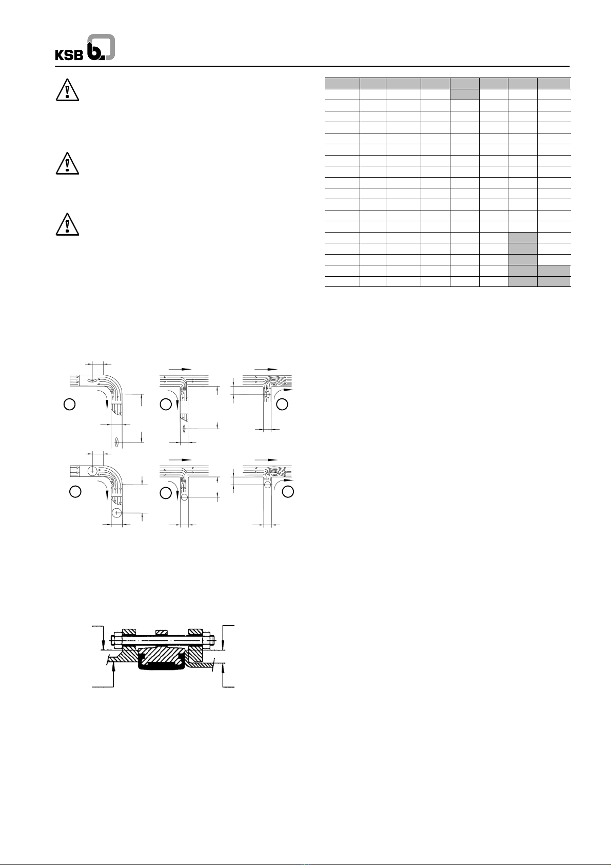
ACHTUNG Die Armaturen dürfen nicht außerhalb des zulässigen
Einsatzbereiches betrieben werden. Die Grenzen sind dem
Typenschild oder dem gültigen Typenblatt zu entnehmen.
Insbesondere dürfen die Werte der Druck-Temperatur-Tabellen nicht
überschritten werden. Der Einsatz außerhalb von vorgenannten
Bedingungen führt zu Überbeanspruchungen, denen die Armaturen
nicht standhalten.
Die Typenblätter sind im Internet unter www.ksb.com --
Produktkatalog abrufbar.
Das Nichtbeachten dieser Warnung kann zu Personen- und
Sachschäden führen, z. B.
-- Verletzungen durch austretende Medien (kalt/heiß, unter Druck,...),
-- Beeinträchtigung der Funktion oder Zerstörung der Armatur.
Die Beschreibungen und Instruktionen in dieser Betriebsanleitung
beziehen sich auf die Standardausführungen, gelten aber auch in
gleicher Weise für Varianten.
Bei angetriebenen Armaturen ist zusätzlich die zum Antrieb
gehörende Betriebsanleitung unbedingt einzuhalten.
Die Betriebsanleitung berücksichtigt nicht
-- Zufälligkeiten und Ereignisse, die bei Montage und Betrieb
auftreten können,
-- die ortsbezogenen Sicherheitsbestimmungen, für deren
Einhaltung -- auch seitens des hinzugezogenen Montagepersonals
-- der Betreiber verantwortlich ist.
Bei Armaturen mit Antrieb ist auch die zum Antrieb gehörende
Betriebsanleitung unbedingt einzuhalten sowie die angegebenen
Anschlußparameter und die Anbauanweisungen.
ACHTUNG Voraussetzung für das Handhaben der Armatur ist der
Einsatz von fachlich geschultem Personal.
Fehlbedienung einer Armatur kann zu nachdrücklichen Folgen für die
gesamte Anlage führen, z. B.
-- Austritt des Mediums,
-- Stillstand einer Anlage/Maschine,
-- Beeinträchtigung/Verringerung/Erhöhung der Wirkung/Funktion
einer Anlage/Maschine.
Bei Rückfragen oder im Schadensfalle wenden Sie sich bitte an die
nächstgelegene KSB-Verkaufsniederlassung.
Bei Rückfragen und Nachbestellungen, bitten wir, die
Baureihen-/Ausführungsbezeichnung, die Werk-Nr. sowie, wenn
möglich, das Baujahr anzugeben.
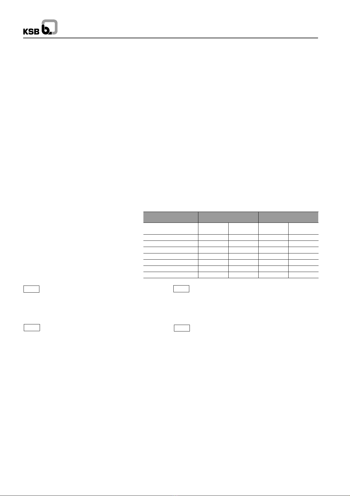
Die technischen Daten (Betriebsdaten) der Armaturen sind in den
technischen Dokumentationen (Typenblatt, Betriebsanleitung) der
jeweiligen Armatur aufgeführt (siehe Abschnitt 6).
Bei Rücksendung der Armaturen zum Hersteller bitte Abschnitt 5
beachten.
4. Sicherheit
Diese Betriebsanleitung enthält grundlegende Hinweise, die bei
Montage und Betrieb zu beachten sind. Daher ist diese
Betriebsanleitung unbedingt vor Montage und Inbetriebnahme vom
Monteur sowie dem zuständigen Fachpersonal/Betreiber zu lesen
und ständig am Einsatzort der Armatur verfügbar sein.
Es sind nicht nur die unter diesem Hauptpunkt Sicherheit
aufgeführten,allgemeinen Sicherheitshinweisezu beachten, sondern
auch die unter den anderen Hauptpunkten eingefügten, speziellen
Sicherheitshinweise.
4.1. Kennzeichnung von Hinweisen in der
Betriebsanleitung
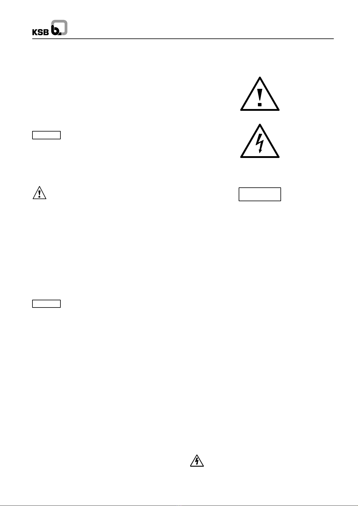
Die in dieser Betriebsanleitung enthaltenen Sicherheitshinweise, die
bei Nichtbeachtung Gefährdungen für Personen hervorrufen können,
sind mit allgemeinem Gefahrensymbol
Sicherheitszeichen nach ISO 3864--B.3.1,
bei Warnung vor elektrischer Spannung mit
Sicherheitszeichen nach ISO 3864--B.3.6.
besonders gekennzeichnet.
Bei Sicherheitshinweisen, deren Nichtbeachtung Gefahren für die
Armatur und deren Funktionen hervorrufen kann, ist das Wort
ACHTUNG
eingefügt.
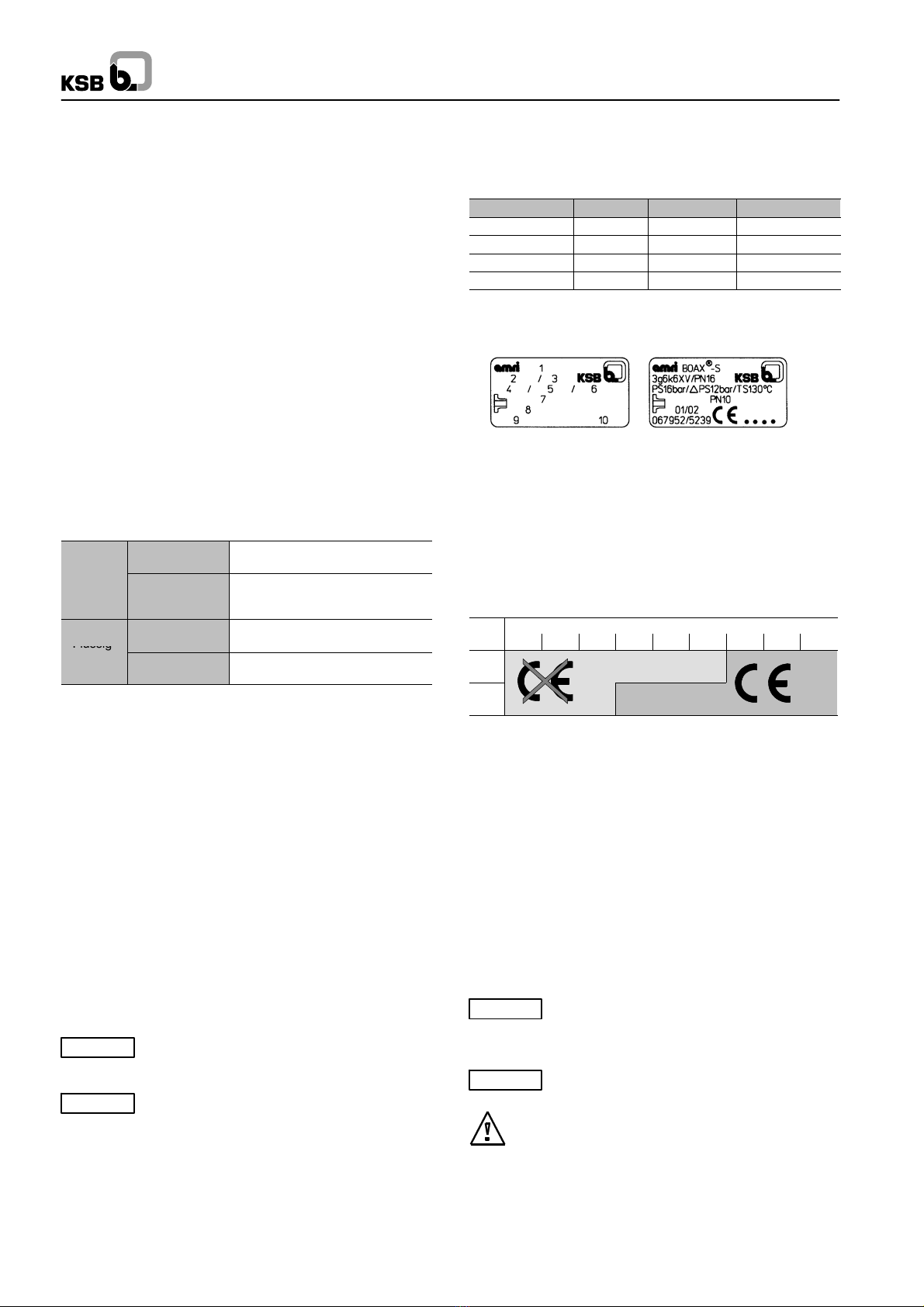
Direkt an der Armatur angebrachte Hinweise (wie z.B. Nenndruck)
müssen unbedingt beachtet und in vollständig lesbarem Zustand
gehalten werden.
4.2. Personalqualifikation und -Schulung
Das Personal für Bedienung, Inspektion und Montage die
entsprechende Qualifikation für diese Arbeiten aufweisen.
Verantwortungsbereich, Zuständigkeit und die Überwachung des
Personals müssen durch den Betreiber genau geregelt sein. Liegen
bei dem Personal nicht die notwendigen Kenntnisse vor, so ist dieses
zu schulen und zu unterweisen. Dies kann, falls erforderlich, im
Auftrag des Betreibers der Armatur durch den Hersteller/Lieferer
erfolgen. Weiterhin ist durch den Betreiber sicherzustellen, dass der
Inhalt der Betriebsanleitung durch das Personal voll verstanden wird.
4.3. Kennzeichnung von Hinweisen in der
Betriebsanleitung
Die Nichtbeachtung der Sicherheitshinweise kann sowohl eine
Gefährdung für Personen als auch für Umwelt und die Armatur zur
Folge haben. Die Nichtbeachtung der Sicherheitshinweise kann zum
Verlust jeglicher Schadensersatzansprüche führen.
Im einzelnen kann Nichtbeachtung beispielsweise folgende
Gefährdungen nach sich ziehen:
-- Versagen wichtiger Funktionen der Armatur/Anlage,
-- Gefährdung von Personen durch elektrische, mechanische und
chemische Einwirkungen,
-- Gefährdung der Umwelt durch Leckage von gefährlichen Stoffen.
4.4. Sicherheitsbewußtes Arbeiten
Die in dieser Betriebsanleitung aufgeführten Sicherheitshinweise, die
bestehenden nationalen Vorschriften zur Unfallverhütung sowie
eventuelle interne Arbeits-, Betriebs- und Sicherheitsvorschriften des
Betreibers sind zu beachten.
4.5. Sicherheitshinweise für den Betreiber /
Bediener
Führen heiße oder kalte Armaturenteile (z. B. Gehäuse oder
Handhebel oder Antriebe) zu Gefahren, müssen diese Teile bauseitig
vom Betreiber gegen Berührung gesichert sein.
Leckagen gefährlicher Medien (z.B. feuergefährlich, heiß) müssen so
abgeführt werden, dass keine Gefährdung für Personen und die
Umwelt besteht. Gesetzliche Bestimmungen sind einzuhalten.
Gefährdung durch elektrische Energie ist auszuschließen.
(Einzelheiten hierzu siehe Norm IEC 364 oder ähnliche
landesspezifische Vorschriften und/oder Vorschriften der örtlichen
Energieversorgungsunternehmen.

8
4.6. Sicherheitshinweise für Inspektions- und
Montagearbeiten
4.6.1 Allgemeines
Für eine angetriebene Armatur müssen sowohl die vorgeschriebene
Vorgehensweise der Armaturbetriebsanleitung als auch die der
Betriebsanleitungen des automatischen Antriebs, des
Stellungsreglers oder Endlagenschalters eingehalten werden.
Der Betreiber hat dafür zu sorgen, dass alle Inspektions- und
Montagearbeiten von autorisiertem und qualifiziertem Fachpersonal
ausgeführt werden, das sich durch eingehendes Studium der
Betriebsanleitung ausreichend informiert hat.
Arbeiten an den Armaturen dürfen nur vorgenommen werden, wenn die
Armaturen nicht mehr unter Druck stehen und auf 60°C abgekühlt sind.
Vor Arbeiten an Armaturen mit Antrieben müssen die elektrischen
Anschlüsse des Stellantriebes von der Stromversorgung abgeklemmt
sind. Die in der Betriebsanleitungen vorgeschriebene
Vorgehensweise zum Stillsetzen des Stellantriebes muss unbedingt
eingehalten werden.
Armaturen, die mit gesundheitsgefährdenden Medien in Berührung
kommen, müssen dekontaminiert werden.
Unmittelbar nach Abschluß der Arbeiten müssen alle Sicherheits- und
Schutzeinrichtungen wieder angebracht bzw. in Funktion gesetzt werden.
Vor der Wiederinbetriebnahme sind die im Abschnitt Inbetriebnahme
aufgeführten Punkte zu beachten.
4.6.2 Endarmatur
Als Endarmatur und Demontage der nicht unter Druck stehenden
Rohrleitung bei Umgebungstemperatur der Standardarmaturen.
Gas *
o
d
e
r
gefährlich
(Gruppe 1) All DN: nicht erlaubt
oder
Flüssig-
keiten Nicht gefährlich
(Gruppe 2)
DN 200: PS = 10 bar max.
200DN 500: PS = 7 bar max.
DN 500: auf Anfrage
Flüssig-
gefährlich
(Gruppe 1) DN 125: PS = 10 bar max.
DN > 125: PS = 7 bar max.
F
l
ü
s
s
i
g
keiten Nicht gefährlich
(Gruppe 2) DN 200: PS = 10 bar max.
DN > 200: PS = 7 bar max.
PS: Differenzdruck
*: Einschließlich Dampf
Anmerkung: Eine Armatur, die am Ende einer Rohrleitung mit einem
Blindflansch eingebaut ist, ist nicht mit einer Endarmatur
gleichzusetzen.
4.7. Eigenmächtiger Umbau und
Ersatzteilherstellung
Umbau oder Veränderungen der Armatur sind nur nach Absprache
mit dem Hersteller zulässig. Originalersatzteile und vom Hersteller
autorisiertes Zubehör dienen der Sicherheit. Die Verwendung anderer
Teile kann die Haftung für die daraus entstehenden Folgen aufheben.
4.8. Unzulässige Betriebsweisen
Die Betriebssicherheit der gelieferten Armatur ist nur bei
bestimmungsgemäßer Verwendung entsprechend Abschnitt
Allgemeines der Betriebsanleitung gewährleistet. Die in der
technischen Dokumentation angegebenen Grenzwerte dürfen auf
keinen Fall überschritten werden.
5. Transport und Lagerung
5.1. Transport
Die Armaturen werden in betriebsfertigem Zustand geliefert.
ACHTUNG Bei Transport und Zwischenlagerung müssen sich die
Armaturen immer in halb geöffneter Stellung befinden und in einem
Karton verpackt sein.
ACHTUNG Die Armatur darf weder am Hals noch am Handrad
oder am Antrieb angeschlagen werden.
Nach der Lieferung bzw. vor dem Einbau ist die Armatur auf
Transportschäden zu überprüfen.
5.2. Lagerung
Die Armaturen müssen so gelagert werden, dass selbst nach längerer
Lagerzeit ein ordnungsgemäßes Funktionieren gewährleistet ist:
-- Während der Lagerung beträgt der Öffnungswinkel der Klappe 5.
-- Geeignete Maßnahmen gegen Verschmutzung, Frost und
Korrosion müssen getroffen werden.
6. Beschreibung der Armaturen
Zeichnungen und weitere Informationen zu den Armaturenbaureihen
finden Sie in den entsprechenden Baureihenheften:
Typ DN PS (bar) Reihungs--Nr.
BOAX-- S 20--600 10/16 8417.1
BOAXMAT-- S 20--500 10/16 8417.1
BOAX-- S F 20--600 10/16 8415.12
BOAXMAT-- S F 20--500 10/16 8415.12
6.1. Kennzeichnung
Die Armaturen sind gekennzeichnet gemäß der Druckgeräterichtlinie
2014/68/EU (DGR).
Typenschild Beispiel
1 -- Armaturentyp
2 – Interner Werkstoffcode
3 -- PN der Armatur / Druckklasse
4 – Max. zulässiger Druck
5 – Max. zulässiger Druck bei Verwendung als Endarmatur oder
einseitigem Abflanschen
6 – Max. zulässige Temperatur
7 -- Flanschbohrbild (wenn bekannt)
8 – Monat und Jahr der Herstellung
9 -- Werksnummer
10 – EG--Markierung mit Angabe der Nr. der Zulassungsstelle
PS DN
32 40 50 65 80 100 125 150 200
10
16
6.2. Funktionsweise
Die Hauptbestandteile der Armatur sind das Gehäuse, die
Antriebswelle, die Welle, die Klappenscheibe und der Ringbalg.
Durch die Formulierung des Ringbalges und seine Herstellung im
Hause wird absolute Dichtigkeit am Wellendurchgang, an den
Flanschen und vor/hinter der Klappenscheibe erzielt.
Verbindung Klappenscheibe--Welle: durch Einpressen der Welle in
die Klappenscheibe.
Betätigung: Die Armaturen werden über Handhebel oder manuelle
bzw. elektrische Stellantriebe betätigt, die auf den Aufbauflansch der
Armatur gem. ISO 5211 geschraubt werden.
Die Armatur ist wartungsfrei.
7. Einbau
7.1. Allgemeines
ACHTUNG Um Leckage, Verformung oder Zerstörung des
Armaturengehäuses zu vermeiden, die Rohrleitung so ausgerichtet
sein, dass nach dem Einbau und nach der Inbetriebnahme weder
Schub-- noch Biegekräfte auf das Gehäuse wirken können.
ACHTUNG Die Dichtflächen der Anschlussflansche müssen
sauber und unbeschädigt sein (Ra 25m).
Zwischen Gehäuse und Flansche darf keine Dichtung
angebracht werden. Die beiden Rohrleitungsflansche
auseinanderdrücken, damit der Ringbalg bei Einbau der Armatur nicht
beschädigt wird. Alle Bohrlöcher auf den Flanschen sind für die
Aufnahme von Schraubverbindungen vorgesehen.

9
Sind auf der Baustelle noch Bauarbeiten im Gange, sind die
nicht installierten Armaturen gegen Staub, Sand und Baumaterial etc.
zu schützen. (Mit geeigneten Mitteln abdecken).
Die Handhebel und Handräder der Stellantriebe dürfen nicht als
Trittleiter verwendet werden!
Armaturen und Rohrleitungen, die für hohe oder niedrige
Temperaturen (> 60 Cbzw.<0C) eingesetzt werden, müssen eine
Schutzisolierung haben oder mit Warnsymbolen versehen sein, da es
gefährlich ist, diese Einrichtungen zu berühren.
Wird die Armatur als Endarmatur eingesetzt, sie gegen
unerlaubtes oder versehentliches Öffnen durch nicht qualifiziertes
Personal geschützt werden, so dass es weder zu Personen-- noch zu
Sachschäden kommen kann.
7.2. Einbaubedingungen
7.2.1. Empfohlene Mindestabstände zwischen der
Stellung der Klappe und dem T--Stück oder
dem Kniestück.
DN
1DN
DNDN
1DN
DN
3DN
DNDN
1DN
1DN
3DN
5--6 DN
3DN
1 3 5
6
4
2
7.2.2 Flanschabmessungen
Anschluß an die Rohrleitung.
Die Rohrleitungsflansche müssen folgende Abmessungen haben.
Ø2a
Ø6
Ø3 Ø2b
Ø6
Ø2a: Maximal zulässiger Innendurchmesser des Rohrflansches
Ø2b: Außendurchmesser
Ø3: Minimaler Rohrflanschinnendurchmesser
Ø6: Minimaler Außendurchmesser der Dichtleiste
Soll die Klappe als Abflanscharmatur eingesetzt werden, dann das
Schraubendrehmoment geringer sein als:
C1 max. (mdaN) für Klappengehäuse Typ 2
C2 max. (mdaN) für Klappengehäuse Typ 4
DN NPS ø2a ø2b ø3 ø6 C1 C2
20 ¾32 27 46 0.4 5
25 137 34 15 55 0.4 5
32 1¼46 43 31 67 0.8 5
40 1½54 49 32 77 1 5
50 263 61 33 86 1.3 5
65 2½80 77 55 107 1.6 5
80 393 89 71 121 2.7 5
100 4116 115 90 141 3 5
125 5141,5 140 119 171 3.2 5
150 6170,5* 169 144 196 4.7 10
200 8222* 220 196 250 610
250 10 276,5* 273 249 306 8.1 10
300 12 327,5* 324 297 358 10 10
350 14 361 356 326 399 10
400 16 412 407 370 452 16
450 18 463 457 422 505 24
500 20 515 508 470 558
600 24 617 610 566 664
* Auf gute Zentrierung des Gehäuses zwischen den Zugbolzen
achten.
7.3. Handhabung
Beim Einbau von Armaturen mit DN > 200 müssen eventuell
geeignete Hebezeuge verwendet werden.
Hebeseile weder am Armaturenhals noch am Handhebel oder dem
Stellantrieb anschlagen.
7.4. Empfehlungen für den Einbau
Vor der Montage
-- Überprüfen, dass keine Schweißperlen und Metallspäne auf den
Dichtungflächen sind.
-- Die Ausrichtung der Leitung und die Parallelität der Flanschen
überprüfen.
-- Überprüfen, dass der Flanschinnendurchmesser dem Mindest-- und
dem Höchstdurchmesser gemäß Tabelle in Abschnitt 7.2.2.
entspricht.
-- Überprüfen, daß die komplette Bewegung der Klappenscheibe bei
Öffnen und Schliessen ungehindert erfolgen kann insbesondere an
den inneren Schweissnähten oder den Rohrenden.
-- Die beiden Flanschen der Leitung etwas auseinanderdrücken,
damit der Ringbalg der Klappe beim Einbau nicht beschädigt wird.
Montage
-- Die Klappenscheibe so weit wie möglich geöffnet einsetzen, ohne
dass jedoch die Scheibe über die Gehäusebreite hinausragt.
-- Die Klappe zwischen die beiden Flansche einschieben und sie
mittels Verbindungsschrauben zentrieren.
-- Die Schrauben langsam über Kreuz anziehen, bis das Gehäuse und
die Flansche der Leitung sich berühren (Metall auf Metall).
Auf richtige Zentrierung des Gehäuses zum Flansch achten.
-- Die Klappe mehrmals betätigen, um sicherzustellen, dass sich die
Scheibe der Klappe problemlos drehen läßt.

10
7.5. Armaturen mit Antrieb
Der Anschluß der elektrischen Leitungen darf nur durch
fachkundiges Personal durchgeführt werden.
Geltende elektrische Vorschriften (z.B. IEC und nationale
Normen müssen beachtet werden). Dies gilt auch bei Einsatz in
gefährlichen Bereichen. Elektrische Ausrüstung wie Stellantriebe,
Klemmenleisten, Magnetkupplungen, Endlagenschalter müssen
überschwemmungssicher installiert werden. Spannung und
Frequenz müssen mit den Angaben auf dem Typenschild
übereinstimmen.
8. Betrieb / Inbetriebnahme
8.1. Allgemeines
Vor Inbetriebnahme sind Werkstoff, Druck- und Temperaturangaben
der Armaturen mit den Betriebsbedingungen des
Rohrleitungssystems zu vergleichen, um Materialbeständigkeit und
Belastbarkeit zu überprüfen.
Eventuell auftretende Druckstöße (Wasserschläge) dürfen
den maximal zulässigen Druck nicht überschreiten.
Schutzmaßnahmen sind vorzusehen.
Bei Neuanlagen und besonders nach Reparaturen ist das
Leitungssystem bei voll geöffneten Armaturen zu spülen, damit für die
Dichtflächen schädliche Feststoffe bzw. Schweißperlen entfernt
werden.
8.2. Betrieb
Die Stellung der Klappenscheibe wird durch die Stellungsanzeige am
Stellantrieb oder durch den Zeiger am Handhebel angezeigt. Die
Armaturen werden durch Drehen im Uhrzeigersinn geschlossen und
durch Drehen in der entgegengesetzten Richtung geöffnet.
8.3. Funktionsüberprüfung
Die Absperrfunktion der eingebauten Armaturen ist vor der
Inbetriebnahme durch mehrmaliges Öffnen und Schließen zu
überprüfen.
8.4. Armaturen mit Antrieb
Die einstellbaren Endanschläge sowie die Drehmomentschalter der
Stellantriebe sind werksseitig voreingestellt.
Der Kunde muss gegebenenfalls die Einstellung vor Ort während der
Inbetriebnahme anpassen.
9. Ausbau der Armatur aus der
Rohrleitung und Entkuppeln des
Antriebes
Anhand des Typenschildes überprüfen, um welche Armatur es
sich handelt.
Die Klappenscheibe um 10 öffnen.
Die Armatur drucklos sein und, um Verbrennungen zu
vermeiden, soweit abgekühlt sein, dass die Temperatur des Mediums
unter 60 C liegt.
Es besteht Lebensgefahr, wenn eine unter Druck stehende
Armatur geöffnet wird. Bei brennbaren Medien oder Medien, die bei
Kontakt mit der Feuchtigkeit der Umgebung korrosiv reagieren, die
Armatur sorgfältig durchgespült werden. Wenn erforderlich,
Sicherheitskleidung und eine Gesichtsschutzmaske tragen. Je nach
Einbauposition die Armatur vollständig entleert werden.Vor jedem
Transport die Armatur sorgfältig entleert und durchspült werden. Bei
Fragen wenden Sie sich bitte an den KSB--Kundendienst.
Werden elektrische Stellantriebe ausgebaut, die
Stromzufuhr unterbrochen werden.
Ausbau der Armatur und des Stellantriebes aus der Rohrleitung.
Beim Ausbau der Armatur aus der Rohrleitung den Ringbalg nicht
beschädigen. Die Rohrleitungsflansche ausreichend
auseinanderdrücken, damit die Armatur leicht entfernt werden kann.
Markieren, wie der Stellantrieb auf die Armatur aufgebaut war.
Stellantrieb entkuppeln. Dabei auf die Verbindungsschrauben
achten.

11
3. Généralités
Ces instructions de fonctionnement s’appliquent aux robinets à papillon
centré à étanchéité élastomère KSB (se reporter au paragraphe 6).
La conception, la fabrication et les contrôles des robinets KSB sont soumis
à un Système d’Assurance Qualité conforme à la norme EN ISO 9001 et à
la Directive des Equipements Sous Pression 2014/68/UE (DESP).
Dans une configuration de robinet avec actionneur, autre que manuel, le
sous ensemble ainsi constitué peut répondre aux exigences de la directive
machine 2006/42/EC en tant que quasi machine dans l’acceptation de la
directive.
Une installation correcte est nécessaire pour assurer un bon
fonctionnement de ces robinets.
Le fabricant ne peut être considéré comme responsable du mauvais
fonctionnement de ces robinets si les instructions de service ne sont
pas respectées.
ATTENTION Le fonctionnement des robinets en dehors de la plage
de fonctionnement admissible n’est pas autorisé. Les limites sont
stipulées sur la plaque signalétique ou dans la notice descriptive. Les
valeurs indiquées dans les tableaux de pressions et de températures
ne doivent pas être dépassées. Toute utilisation en dehors des limites
spécifiées causerait une surcharge des robinets qu’ils ne pourraient
supporter.
Les notices descriptives peuvent être consultées dans notre
catalogue Produits sur Internet à l’adresse www.ksb.com
Le non--respect de cette règle est susceptible de causer des
dommages et blessures tant au personnel qu’aux installations :
-- Blessures dues aux fuites de liquide (froid/chaud, inflammable ou
sous--pression)
-- Fonctionnement incorrect ou destruction du robinet.
Les descriptions et instructions reprises dans cette notice se
rapportent aux versions standard, mais également aux versions
spéciales s’y rapportant.
Ces instructions de service ne tiennent pas compte :
-- des incidents pouvant se produire pendant la mise en place et le
fonctionnement.
-- des règles de sécurité locales. L’utilisateur a la responsabilité de
s’assurer que ces règles sont appliquées et il en est de même pour
les équipes de montage impliquées.
Pour les robinets motorisés, les paramètres de raccordement
spécifié, les instructions d’installation et la notice d’instructions de
service de l’actionneur doivent être respectés.
ATTENTION La manipulation de ces robinets nécessitent un
personnel expérimenté et qualifié.
Le personnel responsable du fonctionnement et de l’installation du
robinet se doit de connaître l’interaction entre le robinet et l’ensemble
dans lequel il se trouve.
Des erreurs concernant le robinet de la part de l’opérateur peuvent
avoir des conséquences graves sur la marche de l’usine, par exemple :
-- fuite de produit
-- perte de production usine/machine
-- effets contraires réduction ou augmentation du rendement par
rapport à usine/machine.
Pour toutes autres questions ou en cas de dommages au robinet,
veuillez prendre contact avec l’Agence Commerciale KSB.
Pour toutes autres questions et commandes supplémentaires,
veuillez spécifier toutes les indications inscrites sur la plaque
d’identité.
Les spécifications (conditions de fonctionnement) des robinets sont
reprises dans cette notice ainsi que dans la notice technique du
robinet concerné (se reporter au paragraphe 6).
En cas de retour du robinet au fabricant, veuillez vous référer au
paragraphe 5.
4. Sécurité
Cette notice contient des instructions de base à respecter pour le
fonctionnement. Il est donc vital pour le monteur et l’opérateur de lire
cette notice avant de procéder à l’installation et la mise en route du
robinet. De même, cette notice doit toujours être disponible sur le site
où le robinet est monté.
ll ne suffit pas de respecter les instructions générales reprises au
paragraphe ”sécurité”, il faut également respecter celles données
dans les autres paragraphes.
4.1. Symboles de sécurité utilisés dans les
instructions de fonctionnement
Les instructions de sécurité énoncées dans cette notice d’instructions
qui seraient à même de par leur non--respect de causer des dommages
corporels sont spécialement marquées par le symbole de risque :
conforme à la norme ISO 3864--B.3.1.
ou par le symbole d’avertissement tension électrique :
conforme à la norme ISO 3864--B.3.6.
Les instructions qui pourraient impliquer des risques au robinet et
mettre en cause son fonctionnement en cas de non--observation, sont
repérées par le mot
ATTENTION
Les indications directement attachées au robinet même (telle que par
exemple pression nominale) doivent être respectées et maintenues
lisibles.
4.2. Qualification et formation du personnel
Le personnel affecté au fonctionnement, à l’inspection et à l’
installation doit être parfaitement qualifié pour le travail
correspondant. Les responsabilités, compétences et encadrement du
personnel doivent être clairement définies par l’utilisateur. Si le
personnel en question ne possède pas les connaissances requises,
une formation doit alors lui être proposée. Si jugé nécessaire, le
fabricant/fournisseur fournira une telle formation et instructions à la
demande de l’utilisateur. De plus, l’utilisateur a la responsabilité de
s’assurer que ces dites instructions sont bien comprises par le
personnel en question.
4.3. Dangers en cas de non--respect des
instructions de sécurité
Le non--respect des instructions de sécurité peut causer des
dommages corporels au personnel, des dangers pour
l’environnement et pour le matériel lui--même. Ce non--respect aura
également pour conséquence l’annulation pure et simple de la
garantie.
Cela pourrait par exemple aboutir :
-- à la non--obtention des fonctions essentielles robinet/usine
-- à des résultats non satisfaisants des procédures d’entretien et
réparations prescrites
-- à des dangers pour l’environnement suite à des fuites de matières
dangereuses
4.4. Sensibilisation à la sécurité
Les instructions de sécurité contenues dans cette notice, l’application
des Règles Nationales pour la Prévention des Accidents ainsi que
toutes autres règles propres à l’utilisateur applicables au travail
interne, fonctionnement ou sécurité doivent être prises en compte.
4.5. Instructions de sécurité
utilisateur/opérateur
Toute partie chaude ou froide du robinet (corps ou poignée ou
actionneur) qui pourrait créer un risque de danger doit être protégée
par l’utilisateur contre des contacts accidentels.
Toute fuite de matière dangereuse (par exemple inflammable ou
chaude) doit être éliminer pour éviter tout danger pour les personnes
ou pour l’environnement. La législation s’y référant doit être
strictement respectée.
Tout risque d’accident électrique doit être efficacement
maîtrisé. (Pour les détails, veuillez vous référer à lanorme IEC 364 ou
aux normes nationales équivalentes et/ou aux réglements locaux sur
l’alimentation éléctrique).

12
4.6. lnstructions de sécurité pour les
travaux d’inspection et d’installation
4.6.1 Généralités
Sur un robinet actionné, les instructions de cette présente notice
d’instructions ainsi que celles indiquées dans les notices d’instruction
de l’actionneur, du positionneur et/ou appareil de régulation doivent
être strictement suivies.
L’utilisateur a la responsabilité de s’assurer que les travaux
d’inspection et d’installation soient réalisés par du personnel autorisé,
d’une qualification adéquate qui est familiarisé avec cette notice
d’instructions.
Tout travail sur un robinet ne peut être effectué que s’il est hors
pression et que sa température a été ramenée à 60 °C maximum.
Toute intervention sur des robinets motorisés ne peut être effectué
qu’après déconnexion de la source d’énergie. La procédure décrite
dans les instructions de service pour la mise en arrêt de l’actionneur
doit être respectée.
Les robinets en contact avec des matières dangereuses doivent être
décontaminés. Immédiatement après l’achèvement du travail, tous
les équipements de sécurité doivent être réinstallés et/ou redémarrés.
Avant toute remise en service, veuiller vous référer aux différents
points du paragraphe 8.
4.6.2. Montage bout de ligne
et démontage aval
Utilisation en montage bout de ligne et démontage aval à la
température ambiante des robinets de fabrication standard :
G
a
z
*
o
u
Dangereux
(Groupe 1) Tous DN : non autorisé
G
az
*
ou
liquides Non dangereux
(Groupe 2)
DN 200: PS = 10 bar max.
200DN 500: PS = 7 bar max.
DN 500: sur demande
L
i
q
u
i
d
e
s
Dangereux
(Groupe 1)
DN 125: PS = 10 bar max.
DN > 125: PS = 7 bar max.
L
i
qu
i
d
es Non dangereux
(Groupe 2)
DN 200: PS = 10 bar max.
DN > 200: PS = 7 bar max.
PS: Pression différentielle
*: Incluant la vapeur
NOTA : Un robinet monté au bout d’une tuyauterie avec une
contre--bride pleine à l’aval n’est pas à considérer comme
montage bout de ligne.
4.7. Modification non autorisée
Les équipements ne doivent subir ni changements, ni modifications
sans avoir prélablement consulté le fabricant. Le fabricant ne pourra
pas être jugé responsable des dégats occasionnés par l’utilisation de
pièces ou accessoires n’étant pas d’origine.
4.8. Modes de fonctionnement non autorisés
La sécurité opérationnelle et la fiabilité du robinet fourni ne sont
garanties que dans la limite d’utilisation tel que définie dans la section
3 ”Généralités” de la notice instructions.
Les limites indiquées dans la notice technique ne doivent être
dépassées en aucun cas.
5. Transport et stockage intermédiaire
5.1. Transport
Les robinets sont livrés prêts à l’utilisation.
ATTENTION Pour le transport et le stockage, les robinets doivent
être maintenus en position semi--fermée et être emballés dans des
caisses carton.
ATTENTION Pour éviter tout dommage, ne pas élinguer le robinet
par le col, volant ou l’actionneur.
Après livraison ou avant l’installation, il est nécessaire de vérifier le
robinet afin de détecter des dommages éventuels suite au transport.
5.2. Stockage intermédiaire
Les robinets doivent être stockés de façon à fonctionner correctement
même après un stockage prolongé. Ceci inclut :
-- Stockage à 5 °de la position fermée
-- Précautions particulières contre la contamination, le gel et la
corrosion.
6. Description des robinets
Pour les plans en coupe et autres informations relatives à un type de
robinet spécifique, se référer aux livrets techniques suivants :
Type DN (mm) PS (bar) N°livret technique
BOAX-- S 20--600 10/16 8417.1
BOAXMAT-- S 20--500 10/16 8417.1
BOAX-- S F 20--600 10/16 8415.12
BOAXMAT-- S F 20--500 10/16 8415.12
6.1. Marquage
Les robinets sont marqués selon DESP 2014/68/UE .
Marquage de la plaque d’identité Exemple
1 -- Type du robinet
2 -- Codification interne du matériau
3 -- Désignation du robinet PN / Classe
4 -- Pression maximale autorisée
5 -- Pression maximale autorisée utilisation en bout de ligne ou
démontage aval
6 -- Température maximale autorisée
7 -- Raccordement brides de tuyauterie (si connu)
8 -- Mois et année de fabrication
9 -- Numéro de série
10 -- Marquage CE avec numéro d’identification de l’organisme notifié
P
S
Size
P
S
32 40 50 65 80 100 125 150 200
10
16
6.2. Principe de fonctionnement
Un robinet est constitué principalement d’un corps, d’un arbre de
manoeuvre, d’un axe inférieur, d’un obturateur et d’une manchette
élastomère.
Le savoir--faire découlant de la formulation et fabrication de la
manchette élastomère assure une étanchéite parfaite au niveau des
passages d’axes, aux brides et au sectionnement amont/aval.
Liaison obturateur/arbre : elle est assurée par un emmanchement
serré de l’arbre dans l’obturateur.
Manoeuvre : Les robinets sont manoeuvrés par des poignées ou
actionneurs quart de tour manuels ou des actionneurs électriques
vissés sur l’embase du robinet suivant la norme ISO 5211.
Ce robinet est indémontable.
7. Installation
7.1. Généralités
ATTENTION Pour éviter toute fuite, déformation ou rupture du
corps, la tuyauterie doit être correctement alignée de telle sorte
qu’aucune poussée ou effort de flexion parasites n’agissent sur les
corps des robinets quand ils sont installés et en service.
ATTENTION Les faces d’étanchéité des brides doivent être
propres et non endommagées (Ra 25m).
Il est interdit de rajouter un joint entre le corps et les brides de la
tuyauterie. Ecarter les deux brides de la tuyauterie pour éviter de
blesser la manchette lors de l’insertion du robinet. Tous les trous des
brides doivent être reliés entre eux par la boulonnerie.

13
Sur une installation en cours de montage, les robinets non
montés doivent être protégés de la poussière, du sable et des
matériaux de construction etc... (couvrir avec des moyens adéquats).
Ne pas utiliser les poignées et les volants d’actionneurs comme
marchepieds !
Les robinets et les tuyauteries utilisés en haute (> 60 °C) ou
basse (< 0 °C) température doivent être soit équipés d’une isolation
de protection soit équipés des symboles de prévention indiquant qu’il
est dangereux de toucher ces robinets.
Si un robinet est utilisé en bout de ligne, il doit être protégé de
tout risque d’ouverture accidentelle ou par des personnes non
autorisées de façon à éviter tout risque de dommage pour le
personnel et les installations.
7.2. Conditions d’installation
7.2.1. Distances minimales recommandées entre
la position du robinet et le Té de
raccordement ou le coude
DN
1DN
DNDN
1DN
DN
3DN
DNDN
1DN
1DN
3DN
5--6 DN
3DN
1 3 5
6
4
2
7.2.2. Cotes de bridage
Raccordements à la tuyauterie.
Les brides de tuyauterie doivent avoir les dimensions suivantes :
Ø2a
Ø6
Ø3 Ø2b
Ø6
Ø2a:Diamètremaxitolérésurlafacedebride
Ø2b : Diamètre extérieur de la partie tubulaire dans le cas de collets
Ø3 : Diamètre mini toléré sur la face de bride
Ø6 : Diamètre mini toléré de l’épaulement de la bride à face
surélevée.
En cas de démontage aval, le couple de serrage de la boulonnerie doit
être limité à la valeur:
C1 maxi (mdaN) pour corps de robinets type 2
C2 maxi (mdaN) pour corps de robinets type 4
DN NPS ø2a ø2b ø3 ø6 C1 C2
20 ¾32 27 46 0.4 5
25 137 34 15 55 0.4 5
32 1¼46 43 31 67 0.8 5
40 1½54 49 32 77 1 5
50 263 61 33 86 1.3 5
65 2½80 77 55 107 1.6 5
80 393 89 71 121 2.7 5
100 4116 115 90 141 3 5
125 5141,5 140 119 171 3.2 5
150 6170,5* 169 144 196 4.7 10
200 8222* 220 196 250 610
250 10 276,5* 273 249 306 8.1 10
300 12 327,5* 324 297 358 10 10
350 14 361 356 326 399 10
400 16 412 407 370 452 16
450 18 463 457 422 505 24
500 20 515 508 470 558
600 24 617 610 566 664
* Vérifier que le corps est bien centré entre les tirants
7.3. Manutention
Des équipements de manutention peuvent être nécessaires pour
l’installation des robinets DN > 200.
Ne pas élinguer par le col du robinet, la poignée ou l’actionneur.
7.4. Recommandations pour l’installation
Avant assemblage
-- Vérifier l’absence de gouttes de soudure et copeaux métalliques sur
les portées de joint.
-- Vérifier l’alignement des conduites et le parallélisme des brides.
-- Vérifier que le diamètre intérieur des brides soit en accord avec les
diamètres minimum et maximum définis dans le tableau paragraphe
7.2.2.
-- Vérifier que rien ne gêne le débattement de l’obturateur lors de
l’ouverture ou la fermeture, en particulier au niveau des soudures
internes ou des extrémités de tuyauterie.
-- Ecarter les deux brides de la tuyauterie pour éviter de blesser la
manchette lors de l’insertion du robinet.
Pendant l’assemblage
-- Ouvrir le robinet en écartant l’obturateur le plus possible de sa
position fermée, en évitant qu’il dépasse du corps.
-- Insérer le robinet entre les deux brides et le centrer par quelques
tirants.
-- Serrer progressivement en étoile les écrous jusqu’au contact
métal--métal entre le corps du robinet et les brides de tuyauterie en
veillant à conserver un bon centrage du corps par rapport à la bride.
-- Manoeuvrer le robinet plusieurs fois pour s’assurer de la bonne
rotation de l’obturateur du robinet.

14
7.5. Robinets actionnés
Les câbles électriques doivent être branchés par du
personnel qualifié.
Les règlements électriques applicables (exemple IEC et
normes nationales), doivent être respectés ainsi que les équipements
situés en zone dangereuse. Tous les équipements électriques tels
que actionneurs, borniers, entrainement magnétique, contacts de fin
de course, etc. doivent être installés en zone non inondable. La
tension et la fréquence doivent correspondre aux indications de la
plaque d’identité.
8. Mise en service
8.1. Généralités
Avant toute mise en service du robinet, la pression, température et
matériaux constitutifs du robinet doivent être comparés aux
conditions réelles de service de l’installation, ceci pour vérifier que le
robinet est capable de résister.
Les pics de pression (coup de bélier) ne doivent en aucun cas
excéder les pressions admissibles du robinet. Des précautions
particulières devront être prises. Dans une nouveau installation, les
circuits devront être rincés avec les robinets complètement ouverts
pour éliminer les solides, exemple gouttes de soudure qui pourraient
endommager la manchette du robinet.
8.2. Fonctionnement
La position de l’obturateur est donnée par l’index de l’actionneur ou
par le levier de la poignée. Les robinets se ferment en tournant dans le
sens horaire et s’ouvrent dans le sens anti--horaire.
8.3. Vérification fonctionnelle
Les fonctions suivantes doivent être vérifiées :
Avant la mise en service, on vérifiera la fonction fermeture enrépétant
plusieurs fois les manoeuvres de fermeture et d’ouverture.
8.4. Robinets motorisés
Les butées réglables et les limiteurs de couple des actionneurs sont
pré--réglées en usine.
Le client peut avoir à compléter l’ajustement sur le site pendant la mise
en service, si nécessaire.
9. Démontage du robinet de la
tuyauterie et désaccouplement de
l’actionneur
Identifier le robinet en consultant la plaque d’identité
Mettre l’obturateur à 10°de l’ouverture.
Le robinet doit être dépressurisé et doit avoir refroidi
suffisamment pour que sa température soit inférieure à 60°Cafin
d’éviter toute brûlure.
Une ouverture des robinets sous pression peut représenter un
risque mortel. Si des substances inflammables ou si des fluides
pouvant devenir corrosifs au contact de l’humidité atmosphèrique ont
circulé dans le robinet, il doit être rincé abondamment. Si nécessaire, il
y aura lieu de porter des vêtements de sécurité et un masque de
protection. En fonction de la position de montage, tout fluide restant
dans le robinet doit être éliminé.
Avant tout transport, les robinets doivent être rincés et vidés avec
soin. Si vous avez des questions, veuillez consulter le Service
Commercial KSB.
Si les actionneurs alimentés électriquement doivent être
déposés ou démontés, l’alimentation doit être coupée avant toute
opération.
Démontage du robinet de la tuyauterie avec son actionneur
Veiller à ne pas endommager la manchette lors du démontage du
robinet de la tuyauterie. Ecarter suffisamment les brides de tuyauterie
afin de permettre facilement l’extraction du robinet.
Identifier la position de montage de l’actionneur.
Désaccoupler l’actionneur et prendre soin de la boulonnerie de
raccordement.

15
3. General
These operating instructions apply to KSB rubber lined butterfly
valves (see section 6).
Design, manufacturing and testing of the KSB valves are subject to a
Quality Assurance System according to EN ISO 9001 and to the
European Pressure Equipment Directive 2014/68/EU (PED).
For a specific product configuration as an actuated valve, the
aggregate can be considered as a partly completed machine
according to the machinery directive 2006/42/EC and comply with the
requirements of the directive.
Correct installation is mandatory to ensure trouble free operation of
the valves.
The manufacturer cannot be made liable for these valves if operating
instructions are not being observed.
ATTENTION The valves must not be operated outside the
permissible operating range. The limits are indicated on the name
plate or currently applicable type leaflet. The pressure-temperature
ratings, in particular, must not be exceeded. Operation of the valves
outside the above-mentioned conditions may result in overloads
which may damage the valves.
The type leaflets can be found at www.ksb.com – product catalogue.
Nonobservance of this warning may lead to personal injury or
property damage, e.g.:
-- Injury caused by escaping fluids (cold/hot, flammable or under
pressure)
-- Incorrect operation or destruction of the valve.
The descriptions and instructions in this manual refer to the standard
versions but also apply to the related variants.
These operating instructions do not take into consideration:
-- incidents which may occur during installation and operation.
-- the local safety regulations. lt is the user’s responsibility to ensure
that these are also observed by the installation staff involved.
For actuated valves, the specified connection parameters and the
installation instructions -- including the operating manual for the
actuator -- must be observed.
ATTENTION Handling a valve requires skilled and experienced
personnel.
The personnel in charge of operation and installation of this valve must
be aware of the interaction between the valve and the plant.
Operator’s errors concerning the valve may have serious
consequences for the entire plant, e.g.:
-- fluid may escape
-- downtime of the plant/machine
-- adverse effect/reduction/increase of the efficiency/function of a
plant/machine.
For further questions or in case of damage to the valve, please contact
your KSB Sales Office.
For further questions and supplementary orders, please always state
the indications of the marking plate.
The specifications (operating data) of the valves are listed in the
technical documentation and type leaflet of the related valve (see also
section 6).
When returning valves to the manufacturer, please refer to section 5.
4. Safety
This manual contains basic instructions to be complied with during
operation. lt is therefore vital for the fitter and the operator/user to read
this manual before installing/commissioning the valve. Also, this
manual must always be available at the site where the valve is
installed.
lt is not enough to observe the general instructions listed in the section
”safety”, the specific safety instructions listed in the other sections
should also be observed.
4.1. Safety Symbols in these Operating
Instructions
Safety instructions put forth in this instructions manual, the
nonobservance of which would involve the risk of personal injury, they
are specially marked with the general hazard symbol:
in accordance with ISO 3864--B.3.1.
or with the electric voltage warning sign:
In accordance with ISO 3864--B.3.6.
Safety instructions the nonobservance of which would involve hazard
to the valve and jeopardize its operation have been marked with the
word
ATTENTION
lnstructions directly attached to the valve, (e.g. nominal pressure)
must be complied with and maintained in a legible condition.
4.2. Qualification of personnel and training
The personnel for operation, maintenance, Inspection and installation
must be adequately qualified for the work involved. The personnel
responsibility, competence and supervision must be clearly defined by
the user. lf the personnel in question is not already in possession of the
required know-how, appropriate training and instructions must be
provided. lf deemed necessary, the manufacturer/supplier will provide
such training and instructions at the user’s request. In addition, the
user is responsible for ensuring that the contents of these operating
instructions are fully understood by the personnel involved.
4.3. Danger or nonobservance of the safety
instructions
Nonobservance of the safety instructions may lead to personal injury
and danger for both the environment and the valve itself.
Nonobservance of these safety instructions will also forfeit the user’s
warranty.
Such noncompliance could result in for example :
-- failure of essential functions of the valve/plant
-- hazard to people by electrical, mechanical or chemical effects
-- hazard to the environment due to leakage of hazardous substances
4.4. Safety Consciousness
The safety instructions contained in this manual, the applicable
national accident prevention regulations and any of the user’s own
applicable internal work, operation or safety instructions must be fully
complied with.
4.5. Safety Instructions for the
User/Operator
Any hot or cold parts of the valve (e.g. body or handle or actuator) that
could cause a hazard must be protected by the user against accidental
contact.
Leakage of hazardous substance (e.g. flammable, hot) must be
drained so as to avoid all danger to people or the environment. All
relevant laws must be observed.
Electrical hazards must be effectively prevented. (For details,
please refer to the IEC 364 or equivalent national standard and/or
local utility energy supply regulations).

16
4.6. Safety lnstructions for Inspection and
Installation work
4.6.1. General
On an actuated valve the operating instructions of the valve must be
strictly followed as well as those of the operating instructions of the
actuators, the limit switch or automation boxes.
The user is responsible for ensuring that all inspection and installation
work is carried out by authorized, adequately qualified staff who are
thoroughly familiar with this instruction manual.
Any work on a valve may only be performed when the valve is
un-pressurized and has cooled down to 60°C.
Any work on actuated valves may only be done after the actuator has
been disconnected from its energy supply. The procedure described
in the operating instructions to shut down the actuator must be
observed.
Valves in contact with hazardous media must be decontaminated.
Immediately following completion of the work, all safety relevant and
protective devices must be reinstalled and/or re-enabled.
Refer to the points listed under section 8 Commissioning.
4.6.2. End of line installation
Use as end of line and downstream dismantling at ambient
temperature of standard range.
G
a
z
*
o
r
Hazardous
(Group 1) All sizes: not authorized
G
az
*
or
liquids Non hazardous
(Group 2)
size 200: PS = 10 bar max.
200size 500: PS = 7 bar max.
size 500: sur demande
L
i
q
u
i
d
s
Hazardous
(Group 1)
size 125: PS = 10 bar max.
size > 125: PS = 7 bar max.
L
i
qu
i
d
sNon hazardous
(Group 2)
size 200: PS = 10 bar max.
size > 200: PS = 7 bar max.
PS: Differential pressure
*: Including steam
NB: A valve fitted at the end of a pipe with a blind flange
downstream is not to be considered as an end of pipe service.
4.7. Unauthorized Modification
The equipment shall not be altered or modified in any way prior to
consultation with the manufacturer. The manufacturer cannot be held
responsible for damage resulting from the use of non--genuine parts or
accessories.
4.8. Inadmissible Modes of Operation
Operational safety and reliability of the valve supplied is only
warranted for its designated use as defined in section 3 ”General” of
the operating instructions.
The limits stated in the technical documentation must not be
exceeded under any circumstances.
5. Transport & Interim Storage
5.1. Transport
The valves in the as-supplied condition are ready for operation.
ATTENTION For Transport and storage, the valves must always be
maintained in the semi--closed position and be packed in cardboard.
ATTENTION To prevent damage, do not hang the valve by its neck,
handle or actuator.
After delivery or prior to installation, the valve should be checked for
damage during transit.
5.2. Interim Storage
The valves must be stored in such a way that correct operation is
assured even after prolonged storage. This comprises:
-- S t o r i n g a t 5 °from the closed position
-- Suitable measures against contamination, frost and corrosion .
6. Description of valves
For drawings and other information pertaining to a specific valve
series, please refer to the relevant series type booklets.
Type DN (mm) PS (bar) Booklet nr.
BOAX-- S 20--600 10/16 8417.1
BOAXMAT-- S 20--500 10/16 8417.1
BOAX-- S F 20--600 10/16 8415.12
BOAXMAT-- S F 20--500 10/16 8415.12
6.1. Marking
The valves are marked to PED 2014/68/EU.
Marking of the identity plate Example
1 -- Valve type model
2 -- Internal material code
3 -- Valve PN / Class designation
4 -- Maximum allowable pressure
5 -- Maximum allowable pressure at end of line or for downstream
dismantling
6 -- Maximum allowable temperature
7 -- Pipe flange drilling pattern (if known)
8 -- Month and year of production
9 -- Equipment serial number
10 -- CE marking with notified body identification number
P
S
Size
P
S
32 40 50 65 80 100 125 150 200
10
16
6.2. Functioning principle
The valve consists mainly of a body, operating shaft, shaft , disc and
rubber liner.
The in--house designed formulated and manufactured rubber liner
achieves the leak tightness at shaft passages, pipe flanges and
downstream/upstream around the disc.
Disc--shaft connection: The disc and shaft connection is achieved
by a forced fixing of the shaft to the disc.
Operation: The valves are quarter--turn operated manually by
handles or gear box or electric actuators bolted on the valve top plate
(as per ISO 5211 standard).
This valve is maintenance free.
7. Installation
7.1. General
ATTENTION To avoid leakage, deformation or rupture of the body,
the piping should be laid out in such a way that no thrust or bending
forces act on the valve bodies when they are installed and operational.
ATTENTION The sealing faces of the flanges must be clean and
undamaged (Ra 25m).

17
lf construction work is still in progress, non--mounted valves
must be protected against dust, sand and building material etc.(cover
with suitable means).
Do not use valve handles and gear handwheels as footholds!
Valves and pipes used for high (> 60 °C) or low (< 0 °C)
temperatures must either be fitted with a protective insulation, or there
must be warning signs fitted showing that it is dangerous to touch
these valves.
lf a valve is used as end-valve in a pipe, this valve should be
protected against unauthorized or unintentional opening to prevent
personal injury or damage to property.
7.2. Installation conditions
7.2.1. Recommended minimum distances
between the position of the valve and of the
T--piece or elbow.
DN
1DN
DNDN
1DN
DN
3DN
DNDN
1DN
1DN
3DN
5--6 DN
3DN
1 3 5
6
4
2
7.2.2. Flanging dimensions
Connection to the piping.
Piping flanges must match the following dimensions.
Ø2a
Ø6
Ø3 Ø2b
Ø6
Ø2a: max. allowable diameter on flange face
Ø2b: external diameter of the pipe when fitting loose plate flange with
lapped pipe end
Ø3: allowed minimum diameter on flange face
Ø6: allowed minimum diameter of raised face.
In case of downstream dismantling, the tightening torque must be
limited to the following value :
C1 maxi (mdaN) for body valves type 2
C2 maxi (mdaN) for body valves type 4
DN NPS ø2a ø2b ø3 ø6 C1 C2
20 ¾32 27 46 0.4 5
25 137 34 15 55 0.4 5
32 1¼46 43 31 67 0.8 5
40 1½54 49 32 77 1 5
50 263 61 33 86 1.3 5
65 2½80 77 55 107 1.6 5
80 393 89 71 121 2.7 5
100 4116 115 90 141 3 5
125 5141,5 140 119 171 3.2 5
150 6170,5* 169 144 196 4.7 10
200 8222* 220 196 250 610
250 10 276,5* 273 249 306 8.1 10
300 12 327,5* 324 297 358 10 10
350 14 361 356 326 399 10
400 16 412 407 370 452 16
450 18 463 457 422 505 24
500 20 515 508 470 558
600 24 617 610 566 664
* Please check the body is well centered between the tie--rods
7.3. Handling
Handling means may be necessary to install valves sizes > 200.
Do not hang the valve by its neck or handle or actuator.
7.4. Recommendations for installation
Before assembly
-- Verify that pipeline flanges are free from metallic chips and weld
splatter.
-- Verify that pipeline flanges are located on the same centreline and
are parallel.
-- Verify that inside diameter of pipeline flange is in accordance with
the minimum and maximum diameters defined in the table of
subchapter 7.2.2.
-- Verify that nothing hinders the complete moving of the disc during
opening or closing, in particular at the internal weld seams or at the
pipe ends.
-- Pull apart the pipeline flanges to allow valve insertion without
damaging the elastomer liner of the valve.
During assembly
-- Place the disc as spaced apart as possible from the closing position,
but without that disc protrudes past the valve’s body.
-- Insert valve between pipeflanges and center using several tie--rods.
-- Screw up progressively the nuts until metal to metal contact is
achieved between the valve body and pipeline flanges, by making
sure the good centering of the body compared with the flange is
maintained.
-- Operate the valve several times to ensure no valve disc obstruction.

18
76.5. Actuated valves
Electrical cables may only be connected by qualified
personnel.
The applicable electrical regulations (e.g. IEC and national
standards), also for equipment in hazardous locations, must be
observed.All electrical equipment such as actuator, switchboard,
magnetic valve drive, limit switch etc. must be installed in floodproof
dry locations.Voltage and frequency must match the indications
stated on the identity plate.
8. Commissioning
8.1. General
Prior to commissioning the valve, the pressure, temperature and
material data stated on the valve should be compared to the actual
operating conditions in the piping system to check whether the valve
can withstand the loads occurring in the system.
Possible pressure surges (water hammer) must not be exceed
the highest admissible pressure. Adequate precautions should be
taken.In new pipe systems and especially after repair work, the
system should be flushed with the valves fully open to remove solids,
e.g. weld beads, which may damage the seats.
8.2. Operation
The position of the disc is indicated by the pointer of the actuator or by
handle lever. The valves are closed by turning in the clockwise
direction (top view) and opened in the counterclockwise direction.
8.3. Functional Check
The following functions should be checked:Before commissioning,
the shut-off-function of the valves should be checked by repeated
opening and closing.
8.4. Actuated valves
Adjustable end stops and torque limiter are pre--adjusted in factory.
The customer may have to complete the adjustment on site during the
commissioning, if necessary
9. Valve removal from piping and
actuator disconnecting
Identify the valve by identity plate.
Place the disc at 10 °opening.
The entire valve must be unpressurized and must have cooled
down sufficiently so that the temperature of the medium is lower than
60°C, to prevent scalding.
Opening pressurized valves will cause danger to life and limbs
lf highly flammable substances or liquids whose residues may cause
corrosion by interaction with the air humidity were handled by the
valve, then the valve should be drained and flushed or vented.lf
necessary, wear safety clothing and a face guard/mask.Depending on
the installation position, any liquid remaining in the valve may have to
be removed.
Prior to possible transport, the valves must be flushed and drained
carefully.lf you have any questions please contact your KSB Sales
Office.
lf actuators powered by an external source of energy (electric)
need to be removed from the valves or dismantled, the energy supply
must be shut down prior to removing the valve from piping.
Remove the valve from the piping with its actuator. Do not
damage the liner during removal the valve from the pipe. Therefore,
pull apart the pipe flanges to allow sufficient clearance.
Identify the mounting position of the actuator
Disconnect the actuator and take care of all bolting parts.

19
Notes

KSB S.A.S
4, allée des Barbanniers 92635 Gennevilliers Cedex (France)
Tel.:+33141477500Fax:+33141477510www.ksb.com
BOAX--- S , B O A X M A T --- S / B O A X --- S F, B O A X M A T --- S F
Legal information/Copyright -- Original operating manual -- all right reserved
Contents provided herein must neither be processed without KSB’express written consent
Subject to technical modification without prior notice.
27.06.178417.8/16--90
Other manuals for BOAX-S
1
This manual suits for next models
3
Table of contents
Languages:
Other KSB Industrial Equipment manuals

KSB
KSB Amarex KRT Manual

KSB
KSB AmaDrainer Box Box Z2 B Installation instructions

KSB
KSB 88980/41 Manual

KSB
KSB Hyper Installation instructions

KSB
KSB 9972073510/200 Manual

KSB
KSB Amarex N Manual

KSB
KSB 4K Series Installation instructions

KSB
KSB Amarex N Manual

KSB
KSB LevelControl Basic 2 User manual

KSB
KSB GIW MDX Installation instructions